Owner's Manual
Page 2
...to User Alteration or modifications carried out without advance contact. 7 U.S.A. Please read all instructions and WARNINGS in this PIONEER product. For your product. Pioneer Electronics (USA) Inc. Should you have any other information. In case the necessary information is written on the bottom... the Speaker Output Terminals ...... 8 Connecting the Power Terminal 9 Setting the Gain for synced amplifier 10 Connecting the Speaker Wires 10 Installation 15 Attaching the Bass boost remote control ........ 15 Example of installation on the floor mat or on the chassis 16 Replacing the ...
...to User Alteration or modifications carried out without advance contact. 7 U.S.A. Please read all instructions and WARNINGS in this PIONEER product. For your product. Pioneer Electronics (USA) Inc. Should you have any other information. In case the necessary information is written on the bottom... the Speaker Output Terminals ...... 8 Connecting the Power Terminal 9 Setting the Gain for synced amplifier 10 Connecting the Speaker Wires 10 Installation 15 Attaching the Bass boost remote control ........ 15 Example of installation on the floor mat or on the chassis 16 Replacing the ...
Owner's Manual
Page 4
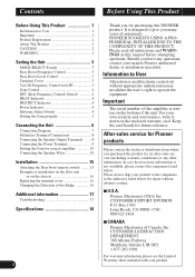
... with a 4 mm hexagonal wrench and remove the terminal cover. Bass Boost Level Control You can select a bass boost level from 40 Hz to 120 Hz with the bass boost control. When using one amplifier only. When switching to the MASTER position when using synchronously connecting two or more ...of connecting the bass boost remote control to the amplifier, see the "Connection Diagram" section. 3 Cut Off Frequency Control for details on the MODE SELECT switch. Setting the Unit MODE SELECT Switch You can select amplifier's sync mode from 40 Hz to 240 Hz. For ...
... with a 4 mm hexagonal wrench and remove the terminal cover. Bass Boost Level Control You can select a bass boost level from 40 Hz to 120 Hz with the bass boost control. When using one amplifier only. When switching to the MASTER position when using synchronously connecting two or more ...of connecting the bass boost remote control to the amplifier, see the "Connection Diagram" section. 3 Cut Off Frequency Control for details on the MODE SELECT switch. Setting the Unit MODE SELECT Switch You can select amplifier's sync mode from 40 Hz to 240 Hz. For ...

Owner's Manual
Page 5
... Subsonic Select Switch The subsonic filter cuts inaudible frequencies below 20 Hz to match the car stereo output level. • For synced amplifier's gain control, see the "Setting the Gain for details. If the sound distorts when the volume is turned up , turn the gain... an AM broadcast with your car stereo, change the BFC switch using with an RCA equipped Pioneer car stereo with max. See the "Troubleshooting" section on . See the "Troubleshooting" section on page 17 for synced amplifier" section. output of 4 V or more, adjust level to eliminate unwanted vibrations and minimize ...
... Subsonic Select Switch The subsonic filter cuts inaudible frequencies below 20 Hz to match the car stereo output level. • For synced amplifier's gain control, see the "Setting the Gain for details. If the sound distorts when the volume is turned up , turn the gain... an AM broadcast with your car stereo, change the BFC switch using with an RCA equipped Pioneer car stereo with max. See the "Troubleshooting" section on . See the "Troubleshooting" section on page 17 for synced amplifier" section. output of 4 V or more, adjust level to eliminate unwanted vibrations and minimize ...
Owner's Manual
Page 6
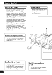
... prevent malfunction of the unit itself and speakers from time to time, contact the nearest authorized PIONEER Service Station. 5 Relationship between the gain of the amplifier and the output power of the head unit Power Normal gain Power Maximum gain Equal power Head...Preout level: 2 V (Standard: 500 mV) Signal waveform when outputting at high volume by the gain control of the amplifier Normal gain Equal power Maximum gain Signal waveform Amplifier gain (normal) Signal waveform Amplifier gain (maximum) • With high output the signal waveform is distorted, if you raise the gain ...
... prevent malfunction of the unit itself and speakers from time to time, contact the nearest authorized PIONEER Service Station. 5 Relationship between the gain of the amplifier and the output power of the head unit Power Normal gain Power Maximum gain Equal power Head...Preout level: 2 V (Standard: 500 mV) Signal waveform when outputting at high volume by the gain control of the amplifier Normal gain Equal power Maximum gain Signal waveform Amplifier gain (normal) Signal waveform Amplifier gain (maximum) • With high output the signal waveform is distorted, if you raise the gain ...
Owner's Manual
Page 7
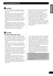
...ranges, the subwoofer may be different colors even if they will be on when the ignition is on the battery and charging system. The amplifier surface could cause damage to the product and injury including burns. Make sure that wires will always be exceeded, causing overheating. • Never...a long time while the engine is at rest or idling. • If the system remote control wire of the amplifier is connected to the power terminal through the vehicle body. • The amplifier increases the load on or off when the engine is for vehicles with cable clamps or adhesive ...
...ranges, the subwoofer may be different colors even if they will be on when the ignition is on the battery and charging system. The amplifier surface could cause damage to the product and injury including burns. Make sure that wires will always be exceeded, causing overheating. • Never...a long time while the engine is at rest or idling. • If the system remote control wire of the amplifier is connected to the power terminal through the vehicle body. • The amplifier increases the load on or off when the engine is for vehicles with cable clamps or adhesive ...

Owner's Manual
Page 8
... (sold separately). Battery wire (sold separately) Connect the male terminal of the car stereo (SYSTEM REMOTE CONTROL). tery wire terminal of the amplifier RATELY fused at the amplifier, connect the bat- to metal body or chassis. Connecting wire with RCA output jacks External Output Bass...RCA pin plugs (sold separately) The ground wires must be connected to the auto-antenna relay control terminal. Connect to the positive (+) terminal of the battery. Each amplifier must be same size. The female terminal can be SEPA- Connecting the Unit Connection Diagram •...
... (sold separately). Battery wire (sold separately) Connect the male terminal of the car stereo (SYSTEM REMOTE CONTROL). tery wire terminal of the amplifier RATELY fused at the amplifier, connect the bat- to metal body or chassis. Connecting wire with RCA output jacks External Output Bass...RCA pin plugs (sold separately) The ground wires must be connected to the auto-antenna relay control terminal. Connect to the positive (+) terminal of the battery. Each amplifier must be same size. The female terminal can be SEPA- Connecting the Unit Connection Diagram •...
Owner's Manual
Page 9
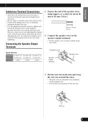
... any excess portions of the wire ties. Expose the end of the speaker wires using nippers or a cutter by observing the status of the amplifier. Put the wire ties in .). 18 mm to the speaker output terminals. • Fix the speaker wires securely with the terminal screw. However..., since excessively tightening the terminal screw of the System remote control has the risk of damaging the wire, be periodically inspected and tightened as necessary. • Do not solder or bind the ends of the...
... any excess portions of the wire ties. Expose the end of the speaker wires using nippers or a cutter by observing the status of the amplifier. Put the wire ties in .). 18 mm to the speaker output terminals. • Fix the speaker wires securely with the terminal screw. However..., since excessively tightening the terminal screw of the System remote control has the risk of damaging the wire, be periodically inspected and tightened as necessary. • Do not solder or bind the ends of the...
Owner's Manual
Page 10
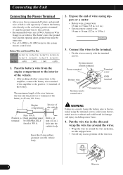
... ground wire and the optional direct ground wire must terminal be same size. • Use a 10 AWG to 20 AWG wire for the system remote control wire. The maximum length of the wire between the fuse and the positive (+) terminal of the battery is 45 cm (1 ft. 6 in the slits... the battery wire terminal of the amplifier to the positive (+) terminal of wires using the terminal screws could cause the terminal area to 25 mm (7/8 in. less than 17 ft. Engine Interior of the wire ties. to 1 in.) • System remote control wire: 14 mm to 5/8 in . to 16 mm (1/2 in .) 3. ...
... ground wire and the optional direct ground wire must terminal be same size. • Use a 10 AWG to 20 AWG wire for the system remote control wire. The maximum length of the wire between the fuse and the positive (+) terminal of the battery is 45 cm (1 ft. 6 in the slits... the battery wire terminal of the amplifier to the positive (+) terminal of wires using the terminal screws could cause the terminal area to 25 mm (7/8 in. less than 17 ft. Engine Interior of the wire ties. to 1 in.) • System remote control wire: 14 mm to 5/8 in . to 16 mm (1/2 in .) 3. ...

Owner's Manual
Page 11
...below and the next page. • When synchronously connecting two or more amplifiers in combination, set the gain control, subsonic select switch, cut off frequency control for the each synced amplifier's gain control to the NORMAL position. ENGLISH ESPAÑOL DEUTSCH FRANÇAIS ...Setup of the Gain Starting with the master amplifier, adjust the gain control on an amplifier which has been set to MASTER with other amplifiers. • When synchronously connecting two or more amplifiers in combination, only use these amplifiers with the MODE SELECT switch. This setting will...
...below and the next page. • When synchronously connecting two or more amplifiers in combination, set the gain control, subsonic select switch, cut off frequency control for the each synced amplifier's gain control to the NORMAL position. ENGLISH ESPAÑOL DEUTSCH FRANÇAIS ...Setup of the Gain Starting with the master amplifier, adjust the gain control on an amplifier which has been set to MASTER with other amplifiers. • When synchronously connecting two or more amplifiers in combination, only use these amplifiers with the MODE SELECT switch. This setting will...
Owner's Manual
Page 16
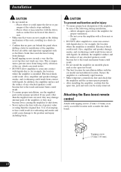
... original fuse. If any wire. Attaching the Bass boost remote control Attach with tapping screws (3 mm × 10 mm) at a sufficiently rigid location. • Make temporary connections first and check that the amplifier and the system operate properly. • After installing the amplifier, confirm that the spare tire, jack and tools can result...
... original fuse. If any wire. Attaching the Bass boost remote control Attach with tapping screws (3 mm × 10 mm) at a sufficiently rigid location. • Make temporary connections first and check that the amplifier and the system operate properly. • After installing the amplifier, confirm that the spare tire, jack and tools can result...

Owner's Manual
Page 19
Bass boost ...Frequency: 40 Hz to 120 Hz Level: 0 / 6 / 9 / 12 dB Gain control ...RCA: 400 mV to 6.5 V Maximum input level / impedance ...RCA: 6.5 V / 22 kΩ Power output 750 W RMS × 1 channel (at 4 Ω and 1% THD+N) 1 500 W RMS × 1 channel .... Use this unit when an audio signal is nearly the maximum current drawn by this value when working out total current drawn by multiple power amplifiers. 18 ENGLISH ESPAÑOL DEUTSCH FRANÇAIS ITALIANO NEDERLANDS Specifications Power source ...14.4 V DC (10.8 V to 15.1 V allowable) Grounding system ...Negative type ...
Bass boost ...Frequency: 40 Hz to 120 Hz Level: 0 / 6 / 9 / 12 dB Gain control ...RCA: 400 mV to 6.5 V Maximum input level / impedance ...RCA: 6.5 V / 22 kΩ Power output 750 W RMS × 1 channel (at 4 Ω and 1% THD+N) 1 500 W RMS × 1 channel .... Use this unit when an audio signal is nearly the maximum current drawn by this value when working out total current drawn by multiple power amplifiers. 18 ENGLISH ESPAÑOL DEUTSCH FRANÇAIS ITALIANO NEDERLANDS Specifications Power source ...14.4 V DC (10.8 V to 15.1 V allowable) Grounding system ...Negative type ...