
Owner's Manual
Page 2
... 2 After-sales service for Pioneer products .......... 2 CAUTION 3 Visit our website 3 CAUTION 3 WARNING 4 Setting the Unit 5 Power Indicator 5 Top Cover 5 Bass Boost Control 5 BFC (Beat Frequency Control) Switch 5 Cut Off Frequency Control 6 LPF (Low-Pass Filter)/HPF (High-Pass Filter) Select Switch 6 Gain Control 6 Input Switch 6 Setting the Gain properly 7 Connecting the Unit 8 Connection Diagram 9 Solderless Terminal Connections 10 Connecting the Power Terminal 10 Connecting the Speaker Output Terminals .... 11 Using the Speaker Input 11 Connecting the Speaker Wires 12...
... 2 After-sales service for Pioneer products .......... 2 CAUTION 3 Visit our website 3 CAUTION 3 WARNING 4 Setting the Unit 5 Power Indicator 5 Top Cover 5 Bass Boost Control 5 BFC (Beat Frequency Control) Switch 5 Cut Off Frequency Control 6 LPF (Low-Pass Filter)/HPF (High-Pass Filter) Select Switch 6 Gain Control 6 Input Switch 6 Setting the Gain properly 7 Connecting the Unit 8 Connection Diagram 9 Solderless Terminal Connections 10 Connecting the Power Terminal 10 Connecting the Speaker Output Terminals .... 11 Using the Speaker Input 11 Connecting the Speaker Wires 12...

Owner's Manual
Page 3
... CANADA Pioneer Electronics of enjoyment. PIONEER SUGGESTS USING A PROFESSIONAL INSTALLER DUE TO THE COMPLEXITY OF THIS PRODUCT. After-sales service for Pioneer products Please contact the dealer or distributor from where you purchased the product for purchasing this PIONEER product...number of this manual before attempting operation. Please read all instructions and WARNINGS in this amplifier is not available, please contact the companies listed below: Please do not ship your product. 2 Keep the card handy for repair without appropriate authorization may invalidate the user...
... CANADA Pioneer Electronics of enjoyment. PIONEER SUGGESTS USING A PROFESSIONAL INSTALLER DUE TO THE COMPLEXITY OF THIS PRODUCT. After-sales service for Pioneer products Please contact the dealer or distributor from where you purchased the product for purchasing this PIONEER product...number of this manual before attempting operation. Please read all instructions and WARNINGS in this amplifier is not available, please contact the companies listed below: Please do not ship your product. 2 Keep the card handy for repair without appropriate authorization may invalidate the user...

Owner's Manual
Page 4
... technologies. 3 Download owner's manuals, order product catalogues, research new products, and much more. Before Using This Product CAUTION • Never replace the fuse with Left + and Right - (Diagram A) or use of your amplifier, and wire two 8 Ω speakers in parallel to achieve a 4 Ω load or use a single 4 Ω speaker per channel. Use of greater value or rating than the original fuse. CAUTION Diagram A - Pioneer Amplifier 2 Ohm Bridged Mode Do NOT install or use a bridged mode for bridging as...
... technologies. 3 Download owner's manuals, order product catalogues, research new products, and much more. Before Using This Product CAUTION • Never replace the fuse with Left + and Right - (Diagram A) or use of your amplifier, and wire two 8 Ω speakers in parallel to achieve a 4 Ω load or use a single 4 Ω speaker per channel. Use of greater value or rating than the original fuse. CAUTION Diagram A - Pioneer Amplifier 2 Ohm Bridged Mode Do NOT install or use a bridged mode for bridging as...

Owner's Manual
Page 5
... protective circuit will cut the power supply to the amplifier (sound will expose you can still hear normal traffic sound. • Check the connections of the power supply and speakers if the fuse of any attached speakers could become hot to cause cancer and birth defects or other reproductive harm. Otherwise you use the special red battery and ground wire [RD-228], which is sold battery wire or the amplifier fuse blows...
... protective circuit will cut the power supply to the amplifier (sound will expose you can still hear normal traffic sound. • Check the connections of the power supply and speakers if the fuse of any attached speakers could become hot to cause cancer and birth defects or other reproductive harm. Otherwise you use the special red battery and ground wire [RD-228], which is sold battery wire or the amplifier fuse blows...

Owner's Manual
Page 6
... "Connection Diagram" section. For instruction of the unit. Bass Boost Control You can select a bass boost level from 0, 6, 9 and 12 dB. BFC (Beat Frequency Control) Switch BFC switch is switched on the bottom of connecting the bass boost remote control to an AM broadcast with a 4 mm hexagonal wrench and remove the top cover. Top Cover Before setting up the unit, unfasten the screws with your car stereo, change the BFC switch using a small standard tip screwdriver. 5 Power Indicator The power indicator lights...
... "Connection Diagram" section. For instruction of the unit. Bass Boost Control You can select a bass boost level from 0, 6, 9 and 12 dB. BFC (Beat Frequency Control) Switch BFC switch is switched on the bottom of connecting the bass boost remote control to an AM broadcast with a 4 mm hexagonal wrench and remove the top cover. Top Cover Before setting up the unit, unfasten the screws with your car stereo, change the BFC switch using a small standard tip screwdriver. 5 Power Indicator The power indicator lights...

Owner's Manual
Page 7
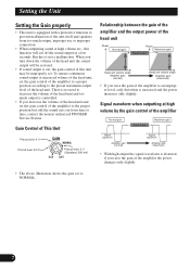
...For connection instructions, see the "Using the Speaker Input" section. 76 output of the car stereo used along with max. Use if you want to cut off frequency from a car stereo external output (subwoofer output) or a car stereo speaker output. When using with RCA pin cord. When using a speaker output, slide the switch to the right. Gain Control If the sound level is too low, even when the volume of 4 V or more, adjust level to match the car stereo output level. • If you are using the speaker input terminals, turn gain control clockwise. In this power amplifier...
...For connection instructions, see the "Using the Speaker Input" section. 76 output of the car stereo used along with max. Use if you want to cut off frequency from a car stereo external output (subwoofer output) or a car stereo speaker output. When using with RCA pin cord. When using a speaker output, slide the switch to the right. Gain Control If the sound level is too low, even when the volume of 4 V or more, adjust level to match the car stereo output level. • If you are using the speaker input terminals, turn gain control clockwise. In this power amplifier...
Owner's Manual
Page 8
... the amplifier the power changes only slightly. • The above illustration shows the gain set . Signal waveform when outputting at increased volume of the head unit, set the gain control of the amplifier to a proper position according to decrease the volume of the head unit and too much output, improper use or improper connection. • When outputting sound at high volume etc., this function will be improperly set to time, contact the nearest authorized PIONEER Service...
... the amplifier the power changes only slightly. • The above illustration shows the gain set . Signal waveform when outputting at increased volume of the head unit, set the gain control of the amplifier to a proper position according to decrease the volume of the head unit and too much output, improper use or improper connection. • When outputting sound at high volume etc., this function will be improperly set to time, contact the nearest authorized PIONEER Service...
Owner's Manual
Page 9
...; Do not ground the speaker wire directly or connect a negative (-) lead wire for several speakers. • This unit is connected to be exceeded, causing overheating. • Never replace the fuse with the standards listed below. input: Min. 300 W Nominal input: Min. 600 W Max. regardless of whether the car stereo is at rest or idling. • Speakers to the power terminal through the vehicle body. • Make sure that wires will blow over them...
...; Do not ground the speaker wire directly or connect a negative (-) lead wire for several speakers. • This unit is connected to be exceeded, causing overheating. • Never replace the fuse with the standards listed below. input: Min. 300 W Nominal input: Min. 600 W Max. regardless of whether the car stereo is at rest or idling. • Speakers to the power terminal through the vehicle body. • Make sure that wires will blow over them...

Owner's Manual
Page 10
... need to the positive (+) terminal of this jack and the bass boost remote control with speaker output, connections defer from the diagram. In either case, you connect with the bass boost remote control wire. RCA input System remote control wire (sold separately). For details, see the "Setting the Unit" section. RCA input jack Amplifier with RCA pin plugs (sold separately) Connect the male terminal of the battery. Ground wire (black) [RD-228] (sold separately) After making all other connections at the amplifier, connect the battery wire terminal of the car stereo (SYSTEM...
... need to the positive (+) terminal of this jack and the bass boost remote control with speaker output, connections defer from the diagram. In either case, you connect with the bass boost remote control wire. RCA input System remote control wire (sold separately). For details, see the "Setting the Unit" section. RCA input jack Amplifier with RCA pin plugs (sold separately) Connect the male terminal of the battery. Ground wire (black) [RD-228] (sold separately) After making all other connections at the amplifier, connect the battery wire terminal of the car stereo (SYSTEM...
Owner's Manual
Page 11
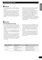
... terminal screw. Pass the battery wire from the engine compartment to the interior of the vehicle. • After making sure to not to clamp the insulating sheath of the wire. • Use the supplied hexagonal wrench to the power terminals of this amplifier (Power terminal, GND terminal, System remote control terminal). The battery wire and the ground wire must be same size. • Use a 10 AWG to the positive (+) terminal of the battery. Battery Wire and Ground Wire Size Wire...
... terminal screw. Pass the battery wire from the engine compartment to the interior of the vehicle. • After making sure to not to clamp the insulating sheath of the wire. • Use the supplied hexagonal wrench to the power terminals of this amplifier (Power terminal, GND terminal, System remote control terminal). The battery wire and the ground wire must be same size. • Use a 10 AWG to the positive (+) terminal of the battery. Battery Wire and Ground Wire Size Wire...
Owner's Manual
Page 12
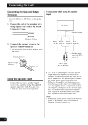
... Connecting the Speaker Output Terminals • Use a 10 AWG to be turned on when the car stereo is turned on . 11 If two or more amplifiers are connected using nippers or a cutter by about 10 mm to connect the system remote control wire in combination, connect the head unit and all of the amplifier is turned on automatically when the car stereo is turned on . Expose the end of the speaker wires using a speaker input wire with RCA pin cord To RCA input...
... Connecting the Speaker Output Terminals • Use a 10 AWG to be turned on when the car stereo is turned on . 11 If two or more amplifiers are connected using nippers or a cutter by about 10 mm to connect the system remote control wire in combination, connect the head unit and all of the amplifier is turned on automatically when the car stereo is turned on . Expose the end of the speaker wires using a speaker input wire with RCA pin cord To RCA input...
Owner's Manual
Page 13
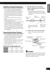
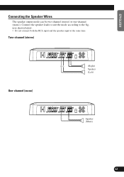
Connect the speaker leads to suit the mode according to the figures shown below. • Do not connect both the RCA input and the speaker input at the same time. Two-channel (stereo) One-channel (mono) (Right) Speaker (Left) Speaker (Mono) 12 ENGLISH ESPAÑOL DEUTSCH FRANÇAIS ITALIANO NEDERLANDS A Title (English) Connecting the Speaker Wires The speaker output mode can be two-channel (stereo) or one-channel (mono).
Connect the speaker leads to suit the mode according to the figures shown below. • Do not connect both the RCA input and the speaker input at the same time. Two-channel (stereo) One-channel (mono) (Right) Speaker (Left) Speaker (Mono) 12 ENGLISH ESPAÑOL DEUTSCH FRANÇAIS ITALIANO NEDERLANDS A Title (English) Connecting the Speaker Wires The speaker output mode can be two-channel (stereo) or one-channel (mono).

Owner's Manual
Page 14
... spare tire board. • The best location for installation differs with the car model and installation location. Also, amplifier and speaker damage, smoke, and overheating could result. • To ensure proper installation, use the supplied parts in the manner specified. Attaching the Bass boost remote control Attach with tapping screws (3 mm × 10 mm) at a sufficiently rigid location. • Make temporary connections first and check that the...
... spare tire board. • The best location for installation differs with the car model and installation location. Also, amplifier and speaker damage, smoke, and overheating could result. • To ensure proper installation, use the supplied parts in the manner specified. Attaching the Bass boost remote control Attach with tapping screws (3 mm × 10 mm) at a sufficiently rigid location. • Make temporary connections first and check that the...

Owner's Manual
Page 15
... at the point marked, and install the amplifier, either on the carpet or directly to be located. 2. Replacing the top cover 1. Place the amplifier where it is to be installed in .) diameter hole Floor mat or chassis 14 Align the unit and top cover, and insert the screw. • The cover can be installed. ENGLISH ESPAÑOL DEUTSCH...
... at the point marked, and install the amplifier, either on the carpet or directly to be located. 2. Replacing the top cover 1. Place the amplifier where it is to be installed in .) diameter hole Floor mat or chassis 14 Align the unit and top cover, and insert the screw. • The cover can be installed. ENGLISH ESPAÑOL DEUTSCH...

Owner's Manual
Page 16
... 10 kHz) Low pass filter ...Cut off frequency: 40 Hz to 500 Hz Cut off slope: -12 dB/oct High pass filter ...Cut off frequency: 40 Hz to 500 Hz Cut off slope: -12 dB/oct Bass boost ...Frequency: 50 Hz Level: 0, 6, 9, 12 dB Gain control ...RCA: 400 mV to 6.5 V Speaker: 1.6 V to 26 V Maximum input level / impedance ...RCA: 6.5 V / 22 kΩ Speaker: 26 V / 90 kΩ Power output 150 W RMS × 2 channels (4 Ω and 1 % THD+N) 600...
... 10 kHz) Low pass filter ...Cut off frequency: 40 Hz to 500 Hz Cut off slope: -12 dB/oct High pass filter ...Cut off frequency: 40 Hz to 500 Hz Cut off slope: -12 dB/oct Bass boost ...Frequency: 50 Hz Level: 0, 6, 9, 12 dB Gain control ...RCA: 400 mV to 6.5 V Speaker: 1.6 V to 26 V Maximum input level / impedance ...RCA: 6.5 V / 22 kΩ Speaker: 26 V / 90 kΩ Power output 150 W RMS × 2 channels (4 Ω and 1 % THD+N) 600...

