Owner's Manual
Page 2
...-sales service for Pioneer products .......... 2 CAUTION 3 Visit our website 3 CAUTION 3 WARNING 4 Setting the Unit 5 Power Indicator 5 Top Cover 5 Cut Off Frequency Control 5 BFC (Beat Frequency Control) Switch 5 LPF (Low-Pass Filter)/HPF (High-Pass Filter) Select Switch 6 Gain Control 6 Input Select Switch 6 Input Switch 6 Setting the Gain properly 7 Connecting the Unit 8 Connection Diagram 9 Solderless Terminal Connections 10 Connecting the Power Terminal 10 Connecting the Speaker Output Terminals .... 11 Using the Speaker Input 11 Connecting the Speakers and Input Wires...
...-sales service for Pioneer products .......... 2 CAUTION 3 Visit our website 3 CAUTION 3 WARNING 4 Setting the Unit 5 Power Indicator 5 Top Cover 5 Cut Off Frequency Control 5 BFC (Beat Frequency Control) Switch 5 LPF (Low-Pass Filter)/HPF (High-Pass Filter) Select Switch 6 Gain Control 6 Input Select Switch 6 Input Switch 6 Setting the Gain properly 7 Connecting the Unit 8 Connection Diagram 9 Solderless Terminal Connections 10 Connecting the Power Terminal 10 Connecting the Speaker Output Terminals .... 11 Using the Speaker Input 11 Connecting the Speakers and Input Wires...
Owner's Manual
Page 3
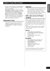
... the unit. Please read all instructions and WARNINGS in this amplifier is designed to the companies at the addresses listed below : Please do not ship your nearest Pioneer authorized dealer or installation specialist. Pioneer Electronics (USA) Inc. PIONEER SUGGESTS USING A PROFESSIONAL INSTALLER DUE ...sales service for its after-sales service (including warranty conditions) or any questions, contact your product to give you for future reference. It is written on the enclosed warranty card. Important The serial number of this manual before attempting operation. CUSTOMER SUPPORT...
... the unit. Please read all instructions and WARNINGS in this amplifier is designed to the companies at the addresses listed below : Please do not ship your nearest Pioneer authorized dealer or installation specialist. Pioneer Electronics (USA) Inc. PIONEER SUGGESTS USING A PROFESSIONAL INSTALLER DUE ...sales service for its after-sales service (including warranty conditions) or any questions, contact your product to give you for future reference. It is written on the enclosed warranty card. Important The serial number of this manual before attempting operation. CUSTOMER SUPPORT...
Owner's Manual
Page 4
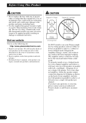
... local authorized Pioneer dealer or call Pioneer customer service. 3 We will keep the details of your amplifier, and wire two 8 Ω speakers in damage to achieve a 4 Ω load or use a single 4 Ω speaker per channel. Improper 4 + Ohm Speaker 8 + Ohm Speaker L+ R- The amplifier surface could result. If you refer to achieve a 2 Ohm (or lower) bridged mode (Diagram B). To properly install or use a bridged mode for bridging as loss or theft. 2 Receive updates on file to help you...
... local authorized Pioneer dealer or call Pioneer customer service. 3 We will keep the details of your amplifier, and wire two 8 Ω speakers in damage to achieve a 4 Ω load or use a single 4 Ω speaker per channel. Improper 4 + Ohm Speaker 8 + Ohm Speaker L+ R- The amplifier surface could result. If you refer to achieve a 2 Ohm (or lower) bridged mode (Diagram B). To properly install or use a bridged mode for bridging as loss or theft. 2 Receive updates on file to help you...

Owner's Manual
Page 5
... such as fuel lines, brake lines and the electrical wiring from contact with wet hands. Connect the battery wire directly to the car battery positive terminal (+) and the ground wire to the amplifier (sound will cut the power supply to the car body. • Do not touch the amplifier with liquids. Detect the cause and solve the problem, then replace the fuse with another one of the same size and rating. • To...
... such as fuel lines, brake lines and the electrical wiring from contact with wet hands. Connect the battery wire directly to the car battery positive terminal (+) and the ground wire to the amplifier (sound will cut the power supply to the car body. • Do not touch the amplifier with liquids. Detect the cause and solve the problem, then replace the fuse with another one of the same size and rating. • To...
Owner's Manual
Page 6
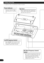
... car stereo, change the BFC switch using a small standard tip screwdriver. 5 If you can select a cut off frequency from 40 Hz to an AM broadcast with a 4 mm hexagonal wrench and remove the top cover. Setting the Unit • To adjust the switch, use standard tip screwdriver if needed. Power Indicator The power indicator lights when the power is switched on the bottom of the unit. BFC (Beat Frequency Control) Switch BFC switch is set to LPF...
... car stereo, change the BFC switch using a small standard tip screwdriver. 5 If you can select a cut off frequency from 40 Hz to an AM broadcast with a 4 mm hexagonal wrench and remove the top cover. Setting the Unit • To adjust the switch, use standard tip screwdriver if needed. Power Indicator The power indicator lights when the power is switched on the bottom of the unit. BFC (Beat Frequency Control) Switch BFC switch is set to LPF...
Owner's Manual
Page 7
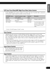
... input plug, set the gain controls to cut the very low frequency range* because it is not necessary for speaker outputs A and B to the same position. • When using . * See the "Cut Off Frequency Control" section. When using with an RCA equipped Pioneer car stereo with an RCA equipped car stereo (standard output of the car stereo to match the car stereo output level. Input Switch It is connected to the speaker output connector and the car stereo system: LPF/HPF Select Switch LPF (Left) OFF (Center) HPF (Right) Audio frequency...
... input plug, set the gain controls to cut the very low frequency range* because it is not necessary for speaker outputs A and B to the same position. • When using . * See the "Cut Off Frequency Control" section. When using with an RCA equipped Pioneer car stereo with an RCA equipped car stereo (standard output of the car stereo to match the car stereo output level. Input Switch It is connected to the speaker output connector and the car stereo system: LPF/HPF Select Switch LPF (Left) OFF (Center) HPF (Right) Audio frequency...
Owner's Manual
Page 8
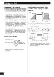
... output power of the head unit Power Normal gain Power Maximum gain Equal power Head unit volume steps Amplifier gain (normal) Head unit volume steps Amplifier gain (maximum) • If you turn down the volume of the head unit the sound output will cut , the gain control of this unit may be restored. • If sound output is cut off the sound output in a few seconds. But this function will be improperly set the gain control of the unit itself and speakers from time to time, contact the nearest authorized PIONEER Service...
... output power of the head unit Power Normal gain Power Maximum gain Equal power Head unit volume steps Amplifier gain (normal) Head unit volume steps Amplifier gain (maximum) • If you turn down the volume of the head unit the sound output will cut , the gain control of this unit may be restored. • If sound output is cut off the sound output in a few seconds. But this function will be improperly set the gain control of the unit itself and speakers from time to time, contact the nearest authorized PIONEER Service...
Owner's Manual
Page 9
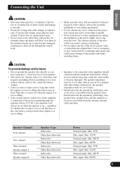
... the ignition is on- Speaker Channel Four-channel Two-channel Three-channel Speaker output A Three-channel Speaker output B Speaker Type Subwoofer Other than subwoofer Subwoofer Other than subwoofer Subwoofer Other than subwoofer Subwoofer Other than the original fuse. To protect the wiring, wrap adhesive tape around it in a short-circuit through the ignition switch (12 V DC), the amplifier will blow over them. If the insulation heats up, it should conform with cable clamps or adhesive tape...
... the ignition is on- Speaker Channel Four-channel Two-channel Three-channel Speaker output A Three-channel Speaker output B Speaker Type Subwoofer Other than subwoofer Subwoofer Other than subwoofer Subwoofer Other than subwoofer Subwoofer Other than the original fuse. To protect the wiring, wrap adhesive tape around it in a short-circuit through the ignition switch (12 V DC), the amplifier will blow over them. If the insulation heats up, it should conform with cable clamps or adhesive tape...
Owner's Manual
Page 10
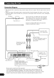
... car stereo does not have a system remote control terminal, connect the male terminal to the positive (+) terminal of the amplifier to the power terminal through the ignition switch. 9 Connecting the Unit Connection Diagram • This diagram shows connections using external output (subwoofer output). Slide the input switch to the left (RCA). • When you need to set the input switch. Grommet Fuse (40 A) × 2 Special red battery wire [RD-228] (sold separately). For details, see the "Using the Speaker Input" section. In either case, you connect with RCA...
... car stereo does not have a system remote control terminal, connect the male terminal to the positive (+) terminal of the amplifier to the power terminal through the ignition switch. 9 Connecting the Unit Connection Diagram • This diagram shows connections using external output (subwoofer output). Slide the input switch to the left (RCA). • When you need to set the input switch. Grommet Fuse (40 A) × 2 Special red battery wire [RD-228] (sold separately). For details, see the "Using the Speaker Input" section. In either case, you connect with RCA...
Owner's Manual
Page 11
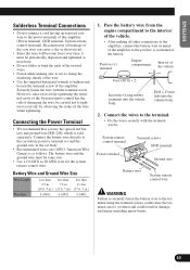
... amplifier (Power terminal, GND terminal, System remote control terminal). Disconnection or breakage of the wire when tightening. Battery Wire and Ground Wire Size Wire Length Wire Size less than less than less than 4.5 m 7.2 m 11.4 m (14 ft. 9 in.) (23 ft. 7 in.) (37 ft. 5 in damage and injury including minor burns. 10 Securely fasten the wire with the terminal screws. Connect the battery wire directly to the car battery positive terminal (+) and the ground wire to the car body. • Recommended wires size...
... amplifier (Power terminal, GND terminal, System remote control terminal). Disconnection or breakage of the wire when tightening. Battery Wire and Ground Wire Size Wire Length Wire Size less than less than less than 4.5 m 7.2 m 11.4 m (14 ft. 9 in.) (23 ft. 7 in.) (37 ft. 5 in damage and injury including minor burns. 10 Securely fasten the wire with the terminal screws. Connect the battery wire directly to the car battery positive terminal (+) and the ground wire to the car body. • Recommended wires size...
Owner's Manual
Page 12
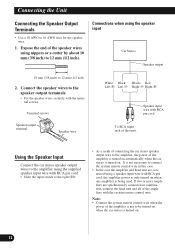
... only turned on . 11 If two or more amplifiers are connected using the speaker input Car Stereo Speaker output 10 mm (3/8 inch) to 12 mm (1/2 inch). Terminal screws Speaker output terminal Speaker wire White: Black: Black: Red: Left + Left ≠ Right ≠ Right + Speaker input wire with RCA pin cord, the amplifier power is not necessary to 16 AWG wire for the speaker wire. 1. Connections when using a speaker input wire with RCA pin cord To RCA input jack of this case. • In the case the amplifier and head unit...
... only turned on . 11 If two or more amplifiers are connected using the speaker input Car Stereo Speaker output 10 mm (3/8 inch) to 12 mm (1/2 inch). Terminal screws Speaker output terminal Speaker wire White: Black: Black: Red: Left + Left ≠ Right ≠ Right + Speaker input wire with RCA pin cord, the amplifier power is not necessary to 16 AWG wire for the speaker wire. 1. Connections when using a speaker input wire with RCA pin cord To RCA input jack of this case. • In the case the amplifier and head unit...

Owner's Manual
Page 13
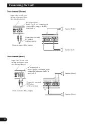
...-channel Input select switch is on the top of the unit. RCA input jack A RCA input jack B (Right) Speaker out A (Left) Speaker out B (Mono) Connecting wires with RCA plugs (sold separately) From car stereo (RCA output) If only one input plug is used , such as when the car stereo has only one output (RCA output), connect the plug to RCA input jack A, but do not connect a plug to the left . ENGLISH ESPAÑOL DEUTSCH FRANÇAIS ITALIANO NEDERLANDS Connecting the Speakers and Input Wires The speaker output mode...
...-channel Input select switch is on the top of the unit. RCA input jack A RCA input jack B (Right) Speaker out A (Left) Speaker out B (Mono) Connecting wires with RCA plugs (sold separately) From car stereo (RCA output) If only one input plug is used , such as when the car stereo has only one output (RCA output), connect the plug to RCA input jack A, but do not connect a plug to the left . ENGLISH ESPAÑOL DEUTSCH FRANÇAIS ITALIANO NEDERLANDS Connecting the Speakers and Input Wires The speaker output mode...
Owner's Manual
Page 14
...the RCA input jack A. RCA input jack A In the case of two-channel mode connect RCA plugs to the left . Connecting wire with RCA plugs (sold separately) From car stereo (RCA output) Speaker (Right) Speaker (Left) Speaker (Mono) Speaker (Mono) 13 Slide this switch to the RCA input jack A. RCA input jack A In the case of two-channel mode connect RCA plugs to the left . Connecting wire with RCA plugs (sold separately) From car stereo (RCA output) Two-channel (Mono) Input select switch is on the top of the unit. Connecting the Unit Two-channel (Stereo) Input select switch is...
...the RCA input jack A. RCA input jack A In the case of two-channel mode connect RCA plugs to the left . Connecting wire with RCA plugs (sold separately) From car stereo (RCA output) Speaker (Right) Speaker (Left) Speaker (Mono) Speaker (Mono) 13 Slide this switch to the RCA input jack A. RCA input jack A In the case of two-channel mode connect RCA plugs to the left . Connecting wire with RCA plugs (sold separately) From car stereo (RCA output) Two-channel (Mono) Input select switch is on the top of the unit. Connecting the Unit Two-channel (Stereo) Input select switch is...
Owner's Manual
Page 15
... interfere with the driver, such as on unstable places such as fuel lines, brake lines and electrical wiring from being cut by vibration of the car, which can be sure of any wire. Secure the amplifier at a sufficiently rigid location. • Make temporary connections first and check that the amplifier and the system operate properly. • After installing the amplifier, confirm that the...
... interfere with the driver, such as on unstable places such as fuel lines, brake lines and electrical wiring from being cut by vibration of the car, which can be sure of any wire. Secure the amplifier at a sufficiently rigid location. • Make temporary connections first and check that the amplifier and the system operate properly. • After installing the amplifier, confirm that the...

Owner's Manual
Page 16
... be installed in the desired direction to match to be located. 2. Align the unit and top cover, and insert the screw. • The cover can be installed. Insert the supplied tapping screws (4 mm × 30 mm) into the screw holes. Tighten the screw with a screwdriver so they make marks where the installation holes are to the amplifier. 2. Push on the screws with...
... be installed in the desired direction to match to be located. 2. Align the unit and top cover, and insert the screw. • The cover can be installed. Insert the supplied tapping screws (4 mm × 30 mm) into the screw holes. Tighten the screw with a screwdriver so they make marks where the installation holes are to the amplifier. 2. Push on the screws with...
Owner's Manual
Page 17
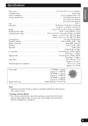
... Hz to 10 kHz) Low pass filter ...Cut off frequency: 40 Hz to 500 Hz Cut off slope: -12 dB/oct High pass filter ...Cut off frequency: 40 Hz to 500 Hz Cut off slope: -12 dB/oct Gain control ...RCA: 400 mV to 6.5 V Speaker: 1.6 V to 26 V Maximum input level / impedance ...RCA: 6.5 V / 22 kΩ Speaker: 26 V / 90 kΩ Power output 75 W RMS × 4 channels (4 Ω and 1 % THD+N) 300 W RMS ×...
... Hz to 10 kHz) Low pass filter ...Cut off frequency: 40 Hz to 500 Hz Cut off slope: -12 dB/oct High pass filter ...Cut off frequency: 40 Hz to 500 Hz Cut off slope: -12 dB/oct Gain control ...RCA: 400 mV to 6.5 V Speaker: 1.6 V to 26 V Maximum input level / impedance ...RCA: 6.5 V / 22 kΩ Speaker: 26 V / 90 kΩ Power output 75 W RMS × 4 channels (4 Ω and 1 % THD+N) 300 W RMS ×...

