
Owners Manual
Page 2
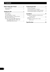
... side 13 Specifications 14 1 Filter)/BPF (Band-Pass Filter) and LOW/HIGH Select Switch 4 Connecting the Unit 5 Connection Diagram 6 Connecting the Power Terminal 7 Connecting the Speaker Output Terminals ...... 8 Connecting the Speakers and Input wires ........ 9 Installation 11 Example of installation on the floor mat or on the chassis 11 Fitting the end cap 12 Example of trouble 2 WARNING 2 Setting the Unit 3 Gain Control 3 Power Indicator 3 Cut Off Frequency Control 3 BFC (Beat Frequency Control) Switch 3 RCA Input Select Switch 4 LPF (Low-Pass Filter)/HPF (High-Pass-
... side 13 Specifications 14 1 Filter)/BPF (Band-Pass Filter) and LOW/HIGH Select Switch 4 Connecting the Unit 5 Connection Diagram 6 Connecting the Power Terminal 7 Connecting the Speaker Output Terminals ...... 8 Connecting the Speakers and Input wires ........ 9 Installation 11 Example of installation on the floor mat or on the chassis 11 Fitting the end cap 12 Example of trouble 2 WARNING 2 Setting the Unit 3 Gain Control 3 Power Indicator 3 Cut Off Frequency Control 3 BFC (Beat Frequency Control) Switch 3 RCA Input Select Switch 4 LPF (Low-Pass Filter)/HPF (High-Pass-

Owners Manual
Page 3
... nearest authorized PIONEER Service Station. Also, do not touch the amplifier when it is wet. • For traffic safety and to the amplifier (sound will cut the power supply to maintain safe driving conditions, keep the volume low enough so that no parts are sold battery wire or the amplifier fuse blows. Detect the cause and solve the problem, then replace the fuse with the EMC Directives (89/336...
... nearest authorized PIONEER Service Station. Also, do not touch the amplifier when it is wet. • For traffic safety and to the amplifier (sound will cut the power supply to maintain safe driving conditions, keep the volume low enough so that no parts are sold battery wire or the amplifier fuse blows. Detect the cause and solve the problem, then replace the fuse with the EMC Directives (89/336...
Owners Manual
Page 4
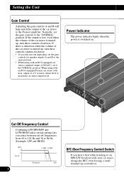
... the car stereo is turned up , turn these controls counter-clockwise. • If you hear a beat while listening to an MW/LW broadcast with your car stereo, change the BFC switch using with max. Setting the Unit Gain Control Adjusting the gain controls A and B will help match the output of the car stereo to match the car stereo output level. Normally, set the gain controls for speaker outputs A and B to the same position. • When using a small standard tip screwdriver. Power Indicator The power indicator lights...
... the car stereo is turned up , turn these controls counter-clockwise. • If you hear a beat while listening to an MW/LW broadcast with your car stereo, change the BFC switch using with max. Setting the Unit Gain Control Adjusting the gain controls A and B will help match the output of the car stereo to match the car stereo output level. Normally, set the gain controls for speaker outputs A and B to the same position. • When using a small standard tip screwdriver. Power Indicator The power indicator lights...
Owners Manual
Page 5
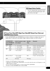
... LOW/HIGH select switch to 120 Hz). *3 If you connect the tweeter directly, you are using. Connect a mid range speaker. *1 See the "Cut Off Frequency Control" section. *2 With CH A, even if the setting is HPF-HIGH, you can only select the same cut the very low frequency range*1 because it is connected to the speaker output connector and the car stereo system: LPF/HPF/BPF and LOW/HIGH Select Switch LPF HIGH LOW HPF HIGH LOW Audio frequency...
... LOW/HIGH select switch to 120 Hz). *3 If you connect the tweeter directly, you are using. Connect a mid range speaker. *1 See the "Cut Off Frequency Control" section. *2 With CH A, even if the setting is HPF-HIGH, you can only select the same cut the very low frequency range*1 because it is connected to the speaker output connector and the car stereo system: LPF/HPF/BPF and LOW/HIGH Select Switch LPF HIGH LOW HPF HIGH LOW Audio frequency...
Owners Manual
Page 6
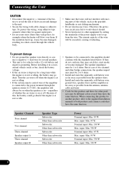
... remote control wire of the amplifier is connected to the power terminal through the vehicle body. • Make sure that have the same function. Before installing it may become damaged. The speaker impedance must be connected to the amplifier should . • Never feed power to other bridge connections, the speaker impedance must be 1 to 8 ohms. But in a recreational vehicle, truck or bus, check the battery voltage. • If the car stereo...
... remote control wire of the amplifier is connected to the power terminal through the vehicle body. • Make sure that have the same function. Before installing it may become damaged. The speaker impedance must be connected to the amplifier should . • Never feed power to other bridge connections, the speaker impedance must be 1 to 8 ohms. But in a recreational vehicle, truck or bus, check the battery voltage. • If the car stereo...
Owners Manual
Page 7
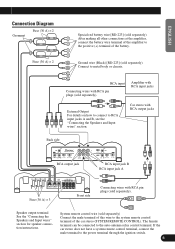
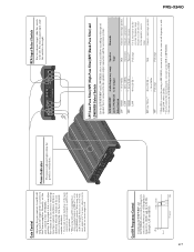
... RCA output jack RCA input jack B RCA input jack A Fuse (30 A) × 3 Front side Connecting wires with RCA pin plugs (sold separately). RCA input Connecting wires with RCA input jacks External Output For details on how to connect to the positive (+) terminal of the car stereo (SYSTEM REMOTE CONTROL). After making all other connections at the amplifier, connect the battery wire terminal of the amplifier to RCA input jacks A and B, see the "Connecting the Speakers and Input wires" section. Amplifier with RCA pin plugs (sold separately). The female terminal can be connected...
... RCA output jack RCA input jack B RCA input jack A Fuse (30 A) × 3 Front side Connecting wires with RCA pin plugs (sold separately). RCA input Connecting wires with RCA input jacks External Output For details on how to connect to the positive (+) terminal of the car stereo (SYSTEM REMOTE CONTROL). After making all other connections at the amplifier, connect the battery wire terminal of the amplifier to RCA input jacks A and B, see the "Connecting the Speakers and Input wires" section. Amplifier with RCA pin plugs (sold separately). The female terminal can be connected...
Owners Manual
Page 8
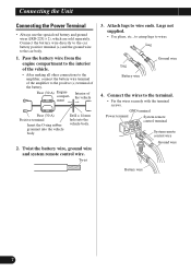
... to the car body. 1. Lug Lug Battery wire Ground wire 4. Twist 3. Fuse (30 A) Engine Interior of the amplifier to the terminal. • Fix the wires securely with the terminal screws. Connect the wires to the positive (+) terminal of the battery. Drill a 14 mm hole into the vehicle body. Connecting the Unit Connecting the Power Terminal • Always use the special red battery and ground wires ([RD-223] × 2), which are sold separately. Pass the battery wire from the...
... to the car body. 1. Lug Lug Battery wire Ground wire 4. Twist 3. Fuse (30 A) Engine Interior of the amplifier to the terminal. • Fix the wires securely with the terminal screws. Connect the wires to the positive (+) terminal of the battery. Drill a 14 mm hole into the vehicle body. Connecting the Unit Connecting the Power Terminal • Always use the special red battery and ground wires ([RD-223] × 2), which are sold separately. Pass the battery wire from the...
Owners Manual
Page 9
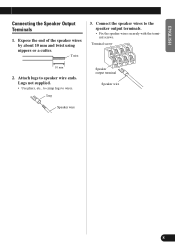
Lug Speaker output terminal Speaker wire Speaker wire DEUTSCH FRANÇAIS ITALIANO NEDERLANDS 8 Terminal screw 10 mm 2. Attach lugs to the speaker output terminals. • Fix the speaker wires securely with the terminal screws. Connect the speaker wires to speaker wire ends. Expose the end of the speaker wires by about 10 mm and twist using nippers or a cutter. ENGLISH ESPAÑOL Connecting the Speaker Output Terminals 1. Twist 3. Lugs not supplied. • Use pliers, etc., to crimp lugs to wires.
Lug Speaker output terminal Speaker wire Speaker wire DEUTSCH FRANÇAIS ITALIANO NEDERLANDS 8 Terminal screw 10 mm 2. Attach lugs to the speaker output terminals. • Fix the speaker wires securely with the terminal screws. Connect the speaker wires to speaker wire ends. Expose the end of the speaker wires by about 10 mm and twist using nippers or a cutter. ENGLISH ESPAÑOL Connecting the Speaker Output Terminals 1. Twist 3. Lugs not supplied. • Use pliers, etc., to crimp lugs to wires.
Owners Manual
Page 10
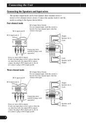
...Connecting wires with RCA plugs (sold separately) From car stereo (RCA output) If only one input plug is used , such as when the car stereo has only one output (RCA output), connect the plug to RCA input jack A, but do not connect a plug to the left . Connecting the Unit Connecting the Speakers and Input wires The speaker output mode can be four-channel, three-channel (stereo + mono) or two-channel (stereo, mono). For four-channel input, slide this switch to RCA input jack B. Three-channel mode RCA input jack B RCA input jack A RCA Input Select Switch For two-channel...
...Connecting wires with RCA plugs (sold separately) From car stereo (RCA output) If only one input plug is used , such as when the car stereo has only one output (RCA output), connect the plug to RCA input jack A, but do not connect a plug to the left . Connecting the Unit Connecting the Speakers and Input wires The speaker output mode can be four-channel, three-channel (stereo + mono) or two-channel (stereo, mono). For four-channel input, slide this switch to RCA input jack B. Three-channel mode RCA input jack B RCA input jack A RCA Input Select Switch For two-channel...
Owners Manual
Page 11
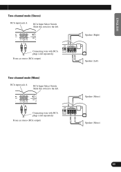
Connecting wire with RCA plugs (sold separately) From car stereo (RCA output) Two-channel mode (Mono) RCA input jack A RCA Input Select Switch Slide this switch to the left . Connecting wire with RCA plugs (sold separately) From car stereo (RCA output) +≠ ≠+ +≠ ≠+ Speaker (Right) Speaker (Left) Speaker (Mono) Speaker (Mono) FRANÇAIS ITALIANO NEDERLANDS 10 ENGLISH ESPAÑOL DEUTSCH Two-channel mode (Stereo) RCA input jack A RCA Input Select Switch Slide this switch to the left .
Connecting wire with RCA plugs (sold separately) From car stereo (RCA output) Two-channel mode (Mono) RCA input jack A RCA Input Select Switch Slide this switch to the left . Connecting wire with RCA plugs (sold separately) From car stereo (RCA output) +≠ ≠+ +≠ ≠+ Speaker (Right) Speaker (Left) Speaker (Mono) Speaker (Mono) FRANÇAIS ITALIANO NEDERLANDS 10 ENGLISH ESPAÑOL DEUTSCH Two-channel mode (Stereo) RCA input jack A RCA Input Select Switch Slide this switch to the left .
Owners Manual
Page 12
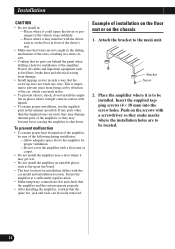
... amplifier at a sufficiently rigid location. • Make temporary connections first and check that the amplifier and the system operate properly. • After installing the amplifier, confirm that the screw tip does not touch any parts other than the supplied ones are to the main unit. If any wire. Protect all cables and important equipment such as the spare tire board. • The best...
... amplifier at a sufficiently rigid location. • Make temporary connections first and check that the amplifier and the system operate properly. • After installing the amplifier, confirm that the screw tip does not touch any parts other than the supplied ones are to the main unit. If any wire. Protect all cables and important equipment such as the spare tire board. • The best...
Owners Manual
Page 15
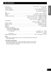
... unit when an audio signal is input. ENGLISH ESPAÑOL DEUTSCH Specifications Power source ...14.4 V DC (10.8 - 15.1 V allowable) Grounding system ...Negative type Current consumption ...43.7 A (at continuous power, 4 Ω) Average current drawn* ...14.5 A (4 Ω for four channels) 26.5 A (4 Ω for two channels) Fuse ...30 A × 3 Dimensions ...264 (W) × 65 (H) × 345 (D) mm Weight ...7.0 kg (Leads for wiring not included) Continuous power output...
... unit when an audio signal is input. ENGLISH ESPAÑOL DEUTSCH Specifications Power source ...14.4 V DC (10.8 - 15.1 V allowable) Grounding system ...Negative type Current consumption ...43.7 A (at continuous power, 4 Ω) Average current drawn* ...14.5 A (4 Ω for four channels) 26.5 A (4 Ω for two channels) Fuse ...30 A × 3 Dimensions ...264 (W) × 65 (H) × 345 (D) mm Weight ...7.0 kg (Leads for wiring not included) Continuous power output...

Service Manual
Page 1
CRT2482 X1R/UC,EW CONTENTS 1. SCHEMATIC DIAGRAM 6 4. PCB CONNECTION DIAGRAM 12 5. ELECTRICAL PARTS LIST 18 6. PIONEER EUROPE N.V. EXPLODED VIEWS AND PARTS LIST 2 3. Haven 1087 Keetberglaan 1, 9120 Melsele, Belgium PIONEER ELECTRONICS ASIACENTRE PTE.LTD. 253 Alexandra Road, #04-01, Singapore 159936 C PIONEER CORPORATION 2000 K-ZZA. ADJUSTMENT 24 7. P.O.Box 1760, Long Beach, CA 90801-1760 U.S.A. Service PRS-X340/X1R/UC Manual BRIDGEABLE FOUR-CHANNEL POWER AMPLIFIER PRS-X340 ORDER NO. MAR. 2000 Printed in Japan...
CRT2482 X1R/UC,EW CONTENTS 1. SCHEMATIC DIAGRAM 6 4. PCB CONNECTION DIAGRAM 12 5. ELECTRICAL PARTS LIST 18 6. PIONEER EUROPE N.V. EXPLODED VIEWS AND PARTS LIST 2 3. Haven 1087 Keetberglaan 1, 9120 Melsele, Belgium PIONEER ELECTRONICS ASIACENTRE PTE.LTD. 253 Alexandra Road, #04-01, Singapore 159936 C PIONEER CORPORATION 2000 K-ZZA. ADJUSTMENT 24 7. P.O.Box 1760, Long Beach, CA 90801-1760 U.S.A. Service PRS-X340/X1R/UC Manual BRIDGEABLE FOUR-CHANNEL POWER AMPLIFIER PRS-X340 ORDER NO. MAR. 2000 Printed in Japan...
Service Manual
Page 6
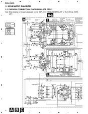
1 2 3 4 PRS-X340 3. SCHEMATIC DIAGRAM 3.1 OVERALL CONNECTION DIAGRAM(GUIDE PAGE) Note: When ordering service parts, be sure to refer to "EXPLODED VIEWS AND PARTS LIST" or "ELECTRICAL PARTS LIST". A A-a Large size A-a A-b SCH diagram A AMP UNIT CN851 ISOLATOR GAIN=1 LOW XOVER B HP/LP FILTER 12dB/OCTAVE 40-120Hz HIGH XOVER NETWORK PCB(A) 3k-9kHz BP FILTER LOW-X TO HIGH-X NETWORK UNIT Consists of • NETWORK PCB • NETWORK PCB CN101 CN102 CN102-2 CN101-2 A-a A-b Guide page A-a A-b Detailed page...
1 2 3 4 PRS-X340 3. SCHEMATIC DIAGRAM 3.1 OVERALL CONNECTION DIAGRAM(GUIDE PAGE) Note: When ordering service parts, be sure to refer to "EXPLODED VIEWS AND PARTS LIST" or "ELECTRICAL PARTS LIST". A A-a Large size A-a A-b SCH diagram A AMP UNIT CN851 ISOLATOR GAIN=1 LOW XOVER B HP/LP FILTER 12dB/OCTAVE 40-120Hz HIGH XOVER NETWORK PCB(A) 3k-9kHz BP FILTER LOW-X TO HIGH-X NETWORK UNIT Consists of • NETWORK PCB • NETWORK PCB CN101 CN102 CN102-2 CN101-2 A-a A-b Guide page A-a A-b Detailed page...

Service Manual
Page 24
... Range. Notes: The Idle current should be set the required voltage range. Measure voltage across Resistor R436 and set VR502 to 5.0 mV 1. Measure voltage across Resistor R434 and set VR504 to the following is performed with no loads on the outputs with no signal input. Specification: Voltage Range: 45 mA ± 5mA 4.0 mV to Voltage Range. 3. PRS-X340 6. ADJUSTMENT -
... Range. Notes: The Idle current should be set the required voltage range. Measure voltage across Resistor R436 and set VR502 to 5.0 mV 1. Measure voltage across Resistor R434 and set VR504 to the following is performed with no loads on the outputs with no signal input. Specification: Voltage Range: 45 mA ± 5mA 4.0 mV to Voltage Range. 3. PRS-X340 6. ADJUSTMENT -
Service Manual
Page 27
... using with an RCA equipped car stereo (standard output of 500 mV), set to the left. Cut Off Frequency Control Combining LPF/HPF/BPF and LOW/HIGH select switch settings lets you must set the CH B to HPF-HIGH. *4 Be sure to set the gain controls to the Pioneer amplifier. LPF (Low-Pass Filter)/HPF (High-Pass Filter)/BPF (Band-Pass Filter) and LOW/HIGH Select Switch Set the LPF/HPF/BPF and LOW/HIGH select switch as with max. Connect a mid range speaker...
... using with an RCA equipped car stereo (standard output of 500 mV), set to the left. Cut Off Frequency Control Combining LPF/HPF/BPF and LOW/HIGH select switch settings lets you must set the CH B to HPF-HIGH. *4 Be sure to set the gain controls to the Pioneer amplifier. LPF (Low-Pass Filter)/HPF (High-Pass Filter)/BPF (Band-Pass Filter) and LOW/HIGH Select Switch Set the LPF/HPF/BPF and LOW/HIGH select switch as with max. Connect a mid range speaker...

Service Manual
Page 28
... "Connecting the Speakers and Input wires" section. After making all other connections at the amplifier, connect the battery wire terminal of the amplifier to the system remote control terminal of the battery. System remote control wire (sold separately) Connect the male terminal of this wire to the positive (+) terminal of the car stereo (SYSTEM REMOTE CONTROL). The female terminal can be connected to metal body or chassis. Connect to the auto-antenna relay control terminal. PRS-X340 Connection Diagram Fuse (30 A) × 2 Grommet Fuse (30 A) × 2 Special red battery wire [RD...
... "Connecting the Speakers and Input wires" section. After making all other connections at the amplifier, connect the battery wire terminal of the amplifier to the system remote control terminal of the battery. System remote control wire (sold separately) Connect the male terminal of this wire to the positive (+) terminal of the car stereo (SYSTEM REMOTE CONTROL). The female terminal can be connected to metal body or chassis. Connect to the auto-antenna relay control terminal. PRS-X340 Connection Diagram Fuse (30 A) × 2 Grommet Fuse (30 A) × 2 Special red battery wire [RD...
Service Manual
Page 29
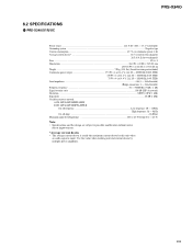
... current drawn by this unit when an audio signal is nearly the maximum current drawn by multiple power amplifiers. 29 PRS-X340 8.2 SPECIFICATIONS - PRS-X340/X1R/UC Power source ...14.4 V DC (10.8 - 15.1 V allowable) Grounding system ...Negative type Current consumption ...43.7 A (at continuous power, 4 Ω) Average current drawn* ...14.5 A (4 Ω for four channels) 26.5 A (4 Ω for two channels) Fuse ...30 A × 3 Dimensions ...264 (W) × 65 (H) ×...
... current drawn by this unit when an audio signal is nearly the maximum current drawn by multiple power amplifiers. 29 PRS-X340 8.2 SPECIFICATIONS - PRS-X340/X1R/UC Power source ...14.4 V DC (10.8 - 15.1 V allowable) Grounding system ...Negative type Current consumption ...43.7 A (at continuous power, 4 Ω) Average current drawn* ...14.5 A (4 Ω for four channels) 26.5 A (4 Ω for two channels) Fuse ...30 A × 3 Dimensions ...264 (W) × 65 (H) ×...

Service Manual
Page 30
Use this unit when an audio signal is input. PRS-X340/X1R/EW Power source ...14.4 V DC (10.8 - 15.1 V allowable) Grounding system ...Negative type Current consumption ...43.7 A (at continuous power, 4 Ω) Average current drawn* ...14.5 A (4 Ω for four channels) 26.5 A (4 Ω for two channels) Fuse ...30 A × 3 Dimensions ...264 (W) × 65 (H) × 345 (D) mm Weight ...7.0 kg (Leads for wiring not included) Continuous power output 37.5 W × 4 (at...
Use this unit when an audio signal is input. PRS-X340/X1R/EW Power source ...14.4 V DC (10.8 - 15.1 V allowable) Grounding system ...Negative type Current consumption ...43.7 A (at continuous power, 4 Ω) Average current drawn* ...14.5 A (4 Ω for four channels) 26.5 A (4 Ω for two channels) Fuse ...30 A × 3 Dimensions ...264 (W) × 65 (H) × 345 (D) mm Weight ...7.0 kg (Leads for wiring not included) Continuous power output 37.5 W × 4 (at...

Service Manual
Page 31
..., CA 90801-1760 U.S.A. DEC. 2000 Printed in Japan Service Manual ORDER NO. CRT2646 BRIDGEABLE FOUR-CHANNEL POWER AMPLIFIER PRS-X340 X1H/UC PRS-X340 X1H/EW - Symbol and Description PRS-X720/X1R/UC PRS-X720/X1H/UC PRS-X320/X1H/UC 1 Screw Assy HEA0047 HEA0057 HEA0057 10 Bracket Assy HXA0323 Not used Not used 10 Screw Assy Not used together with the following manual(s): Model Order No. EXTERIOR SECTION PARTS LIST Part No.
..., CA 90801-1760 U.S.A. DEC. 2000 Printed in Japan Service Manual ORDER NO. CRT2646 BRIDGEABLE FOUR-CHANNEL POWER AMPLIFIER PRS-X340 X1H/UC PRS-X340 X1H/EW - Symbol and Description PRS-X720/X1R/UC PRS-X720/X1H/UC PRS-X320/X1H/UC 1 Screw Assy HEA0047 HEA0057 HEA0057 10 Bracket Assy HXA0323 Not used Not used 10 Screw Assy Not used together with the following manual(s): Model Order No. EXTERIOR SECTION PARTS LIST Part No.


