
Owner's Manual
Page 3
PWM-F110 Table of Contents Warning Statements ...- 4 Parts List ...- 6 Installation Tools ...- 6 Mounting Bracket Installation ...- 7 Wall Stud Location ...- 10 Installing the Flat Panel Display ...- 14 Technical Specifications ...- 16 Warranty ...- 17 Contact Premier Mounts ...- 17 Notes ...- 18 - Installation Manual Page - 3 -
PWM-F110 Table of Contents Warning Statements ...- 4 Parts List ...- 6 Installation Tools ...- 6 Mounting Bracket Installation ...- 7 Wall Stud Location ...- 10 Installing the Flat Panel Display ...- 14 Technical Specifications ...- 16 Warranty ...- 17 Contact Premier Mounts ...- 17 Notes ...- 18 - Installation Manual Page - 3 -

Owner's Manual
Page 4
..., angled ceilings, walls, or any water or vapors possible. PWM-F110 Warning Statements Safety Precautions This wall mount should be installed by improper installation, mounting or setup of the plasma television, misuse, modification or natural disasters. The wall being considered for the...wall mount. Page - 4 - Injury and damage can result from all of the mounting bracket. Keep these installation instructions in an easily accessible location for injury or damage caused by qualified personnel having sufficient skill and competence to the plasma television. Avoid installing the plasma...
..., angled ceilings, walls, or any water or vapors possible. PWM-F110 Warning Statements Safety Precautions This wall mount should be installed by improper installation, mounting or setup of the plasma television, misuse, modification or natural disasters. The wall being considered for the...wall mount. Page - 4 - Injury and damage can result from all of the mounting bracket. Keep these installation instructions in an easily accessible location for injury or damage caused by qualified personnel having sufficient skill and competence to the plasma television. Avoid installing the plasma...

Owner's Manual
Page 5
... procedures before beginning the installation process. Lift and attach the plasma television to the rear of a system or as part of the plasma television. 2. PWM-F110 Mount Overview This PWM-F110 Plasma Wall Mount may be used in conjunction with Griplates, to the Plasma Wall Bracket. Attach the bracket, with the appropriate plasma television. The PWM-F110 plasma wall mount is purchased the installer must take care to be sold...
... procedures before beginning the installation process. Lift and attach the plasma television to the rear of a system or as part of the plasma television. 2. PWM-F110 Mount Overview This PWM-F110 Plasma Wall Mount may be used in conjunction with Griplates, to the Plasma Wall Bracket. Attach the bracket, with the appropriate plasma television. The PWM-F110 plasma wall mount is purchased the installer must take care to be sold...

Owner's Manual
Page 6
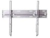
... 1) 5/16" Flat Washers (Qty 4) GriPlates™ (Qty 8) Mounting Brackets (Qty 2) 5/16" x 3" Lag Bolts (wooden studs only) - (Qty 4) Wall Bumpers (Qty 2ea) M8 x 20mm Phillips Head Screws (Qty 6) M4 x 16mm Phillips Head Screws (Qty 8) Installation Tools Phillips Head Screw... the installation and contact Premier Mounts (800) 368-9700 Ext.224. If there are missing and/or damaged before beginning installation. Soft Material/ Blanket Drill Gun Tape Measure 1/2" Socket and Wrench Installation Manual PWM-F110 Parts List NOTE: This wall mount is shipped with all proper installation...
... 1) 5/16" Flat Washers (Qty 4) GriPlates™ (Qty 8) Mounting Brackets (Qty 2) 5/16" x 3" Lag Bolts (wooden studs only) - (Qty 4) Wall Bumpers (Qty 2ea) M8 x 20mm Phillips Head Screws (Qty 6) M4 x 16mm Phillips Head Screws (Qty 8) Installation Tools Phillips Head Screw... the installation and contact Premier Mounts (800) 368-9700 Ext.224. If there are missing and/or damaged before beginning installation. Soft Material/ Blanket Drill Gun Tape Measure 1/2" Socket and Wrench Installation Manual PWM-F110 Parts List NOTE: This wall mount is shipped with all proper installation...

Owner's Manual
Page 10
NOTE: This marking will reference the center of your flat panel display once mounted on Page 16) 2. NOTE: The wall plates have (3) 16" and (1) 24" mounting slot positions (see Technical Specifications on the wall (Figure 9). Figure 9 Page - 10 - Once found, make a pencil marking on the wall. PWM-F110 Wall Stud Location 1. Figure 8 1166"" Measure and mark the viewing height desired...
NOTE: This marking will reference the center of your flat panel display once mounted on Page 16) 2. NOTE: The wall plates have (3) 16" and (1) 24" mounting slot positions (see Technical Specifications on the wall (Figure 9). Figure 9 Page - 10 - Once found, make a pencil marking on the wall. PWM-F110 Wall Stud Location 1. Figure 8 1166"" Measure and mark the viewing height desired...

Owner's Manual
Page 11
Place the bottom portion of the wall plate to the marked wall (16"studs, on the wall. 4. Level the wall plate with the reference arrow pointing up to the marked wall. Mounting Surfaces Wood studs: Drill four (4) ¼" pilot holes to the reference line and mark the four (4) lag bolt mounting points through the wall plate slots on center - Drill Gun Pilot Holes 16" 16" Wall Plate Mounting Slots Level Figure 10 Wood Studs Figure 11 Installation Manual Page - 11 - Concrete wall: Drill four (4) 3/8" pilot holes to the ceiling (Figure 10). Figure 11). PWM-F110 3.
Place the bottom portion of the wall plate to the marked wall (16"studs, on the wall. 4. Level the wall plate with the reference arrow pointing up to the marked wall. Mounting Surfaces Wood studs: Drill four (4) ¼" pilot holes to the reference line and mark the four (4) lag bolt mounting points through the wall plate slots on center - Drill Gun Pilot Holes 16" 16" Wall Plate Mounting Slots Level Figure 10 Wood Studs Figure 11 Installation Manual Page - 11 - Concrete wall: Drill four (4) 3/8" pilot holes to the ceiling (Figure 10). Figure 11). PWM-F110 3.

Owner's Manual
Page 14
FAILURE TO DO SO COULD RESULT IN SERIOUS INJURY AND POSSIBLE DAMAGE TO THE FLAT PANEL. 1. Raise the flat panel with the mounting brackets secured to the flat panel and insert the top hooks from each bracket to the rod from the wall plates (Figure 14). Installation Manual PWM-F110 Installing the Flat Panel Display WARNING: AT LEAST (2) QUALIFIED PERSONNEL ARE STRONGLY RECOMMENDED FOR INSTALLATION OF THIS PRODUCT. Wall Plate Top Figure 14 Bottom Page - 14 -
FAILURE TO DO SO COULD RESULT IN SERIOUS INJURY AND POSSIBLE DAMAGE TO THE FLAT PANEL. 1. Raise the flat panel with the mounting brackets secured to the flat panel and insert the top hooks from each bracket to the rod from the wall plates (Figure 14). Installation Manual PWM-F110 Installing the Flat Panel Display WARNING: AT LEAST (2) QUALIFIED PERSONNEL ARE STRONGLY RECOMMENDED FOR INSTALLATION OF THIS PRODUCT. Wall Plate Top Figure 14 Bottom Page - 14 -

Owner's Manual
Page 15
PWM-F110 2. Use the wall bumper to the rods (Figure 15). CAUTION: Do not over tighten the ¼"-20 screws to adjust your flat panel. Wall Plate Wall Bumper Figure 15 Installation Manual Page - 15 - Make any lateral shift adjustments and lock it by tightening the two (2) ¼"-20 Phillips screws found on the bottom of the wall carefully. NOTE: To remove the flat panel from the wall, simply back off the ¼"-20 screws using a Phillips screwdriver and lift the unit of the mounting brackets.
PWM-F110 2. Use the wall bumper to the rods (Figure 15). CAUTION: Do not over tighten the ¼"-20 screws to adjust your flat panel. Wall Plate Wall Bumper Figure 15 Installation Manual Page - 15 - Make any lateral shift adjustments and lock it by tightening the two (2) ¼"-20 Phillips screws found on the bottom of the wall carefully. NOTE: To remove the flat panel from the wall, simply back off the ¼"-20 screws using a Phillips screwdriver and lift the unit of the mounting brackets.

Owner's Manual
Page 16
Leveling feet (88.9) (31.75) (606.92) (49.53) (127) Page 16 (36.91) Figure 16 Installation Manual Mounting brackets C. ¼" x 20 Safety screws D. PWM-F110 Technical Specifications (406.4) (406.4) (711.2) (406.4) A. Wall plate B.
Leveling feet (88.9) (31.75) (606.92) (49.53) (127) Page 16 (36.91) Figure 16 Installation Manual Mounting brackets C. ¼" x 20 Safety screws D. PWM-F110 Technical Specifications (406.4) (406.4) (711.2) (406.4) A. Wall plate B.