
Owner's Manual
Page 3
Installation Manual Page - 3 - PWM-F110 Table of Contents Warning Statements ...- 4 Parts List ...- 6 Installation Tools ...- 6 Mounting Bracket Installation ...- 7 Wall Stud Location ...- 10 Installing the Flat Panel Display ...- 14 Technical Specifications ...- 16 Warranty ...- 17 Contact Premier Mounts ...- 17 Notes ...- 18 -
Installation Manual Page - 3 - PWM-F110 Table of Contents Warning Statements ...- 4 Parts List ...- 6 Installation Tools ...- 6 Mounting Bracket Installation ...- 7 Wall Stud Location ...- 10 Installing the Flat Panel Display ...- 14 Technical Specifications ...- 16 Warranty ...- 17 Contact Premier Mounts ...- 17 Notes ...- 18 -

Owner's Manual
Page 4
PWM-F110 Warning Statements Safety Precautions This wall mount should be used on vertical walls only. The entire installation instructions should install the mount and set up the plasma television in order to fall from the wall causing personal injury and damage. The wall being considered for..., do so may collect dust quicker than wall mounting. Damage and injury could cause a risk of the mounting bracket. Installation Manual Avoid installing the plasma in the correct locations. The mount is vibration, movement or danger of direct heat energy. Do not install near...
PWM-F110 Warning Statements Safety Precautions This wall mount should be used on vertical walls only. The entire installation instructions should install the mount and set up the plasma television in order to fall from the wall causing personal injury and damage. The wall being considered for..., do so may collect dust quicker than wall mounting. Damage and injury could cause a risk of the mounting bracket. Installation Manual Avoid installing the plasma in the correct locations. The mount is vibration, movement or danger of direct heat energy. Do not install near...

Owner's Manual
Page 5
... Bracket to the rear of the plasma television. 2. Read the installation instructions completely in order to an appropriate wall. The PWM-F110 plasma wall mount is to be used in conjunction with Griplates, to an appropriate wall. 3. Installation Manual Page - 5 - As described below, there are three main steps involved in this product. PWM-F110 Mount Overview This PWM-F110 Plasma...
... Bracket to the rear of the plasma television. 2. Read the installation instructions completely in order to an appropriate wall. The PWM-F110 plasma wall mount is to be used in conjunction with Griplates, to an appropriate wall. 3. Installation Manual Page - 5 - As described below, there are three main steps involved in this product. PWM-F110 Mount Overview This PWM-F110 Plasma...

Owner's Manual
Page 6
If there are missing and/or damaged before beginning installation. Wall Plate (Qty 1) 5/16" Flat Washers (Qty 4) GriPlates™ (Qty 8) Mounting Brackets (Qty 2) 5/16" x 3" Lag Bolts (wooden studs only) - (Qty 4) Wall Bumpers (Qty 2ea) M8 x 20mm Phillips Head Screws (Qty 6) M4 x 16mm Phillips Head Screws (Qty... the installation and contact Premier Mounts (800) 368-9700 Ext.224. Soft Material/ Blanket Drill Gun Tape Measure 1/2" Socket and Wrench Installation Manual PWM-F110 Parts List NOTE: This wall mount is shipped with all proper installation hardware and components.
If there are missing and/or damaged before beginning installation. Wall Plate (Qty 1) 5/16" Flat Washers (Qty 4) GriPlates™ (Qty 8) Mounting Brackets (Qty 2) 5/16" x 3" Lag Bolts (wooden studs only) - (Qty 4) Wall Bumpers (Qty 2ea) M8 x 20mm Phillips Head Screws (Qty 6) M4 x 16mm Phillips Head Screws (Qty... the installation and contact Premier Mounts (800) 368-9700 Ext.224. Soft Material/ Blanket Drill Gun Tape Measure 1/2" Socket and Wrench Installation Manual PWM-F110 Parts List NOTE: This wall mount is shipped with all proper installation hardware and components.

Owner's Manual
Page 7
...pencil lightly mark the center of the chassis (Figure 1). 2. Measuring tape Top of flat panel Inverted flat panel CL Mark the center CL Bottom of flat panel Inverted flat panel of the flat panel Figure 1 Figure 2 Installation Manual Page - 7 - AT LEAST (2) QUALIFIED PERSONNEL ARE ...OF THIS PRODUCT. FAILURE TO DO SO COULD RESULT IN SERIOUS INJURY AND POSSIBLE DAMAGE TO THE FLAT PANEL. 1. USE A BLANKET, FOAM, ETC. PWM-F110 Mounting Bracket Installation NOTE: Proper installation procedure by qualified personnel as outlined in serious personal injury and possible damage ...
...pencil lightly mark the center of the chassis (Figure 1). 2. Measuring tape Top of flat panel Inverted flat panel CL Mark the center CL Bottom of flat panel Inverted flat panel of the flat panel Figure 1 Figure 2 Installation Manual Page - 7 - AT LEAST (2) QUALIFIED PERSONNEL ARE ...OF THIS PRODUCT. FAILURE TO DO SO COULD RESULT IN SERIOUS INJURY AND POSSIBLE DAMAGE TO THE FLAT PANEL. 1. USE A BLANKET, FOAM, ETC. PWM-F110 Mounting Bracket Installation NOTE: Proper installation procedure by qualified personnel as outlined in serious personal injury and possible damage ...

Owner's Manual
Page 8
PWM-F110 3. Lay the mounting brackets on the side of the display (stamped arrows facing out) - (Figure 3). Match the center of viewing guide with the centerline you marked in step 1 (Figure 4). 5 The mounting brackets are designed with a center of viewing guide on the back of them (Figure 5). Page - 8 - Installation Manual Mounting Brackets Figure 3 Bottom of Flat Panel 4.
PWM-F110 3. Lay the mounting brackets on the side of the display (stamped arrows facing out) - (Figure 3). Match the center of viewing guide with the centerline you marked in step 1 (Figure 4). 5 The mounting brackets are designed with a center of viewing guide on the back of them (Figure 5). Page - 8 - Installation Manual Mounting Brackets Figure 3 Bottom of Flat Panel 4.

Owner's Manual
Page 9
...™ have to the flat panel. Once the mounting brackets are aligned, secure the Griplate™ to be facing up and the bottom dimples must be facing down. Use (1) Griplate™ per mounting point (Figure 7). NOTE: The dimples of Flat Panel M4 M5 M6 M8 DIMPLES FACING... fit the hardware that your flat panel uses M8 x 20 Phillip screws, use the M8 mounting points (Figure 6). 7. PWM-F110 Mounting Bracket CL Bottom of Flat Panel Center of Viewing Guide Align the Mounting Brackets Figure 4 Bottom of the Flat Panel Figure 5 Center of Flat Panel 6. EXAMPLE: If your flat...
...™ have to the flat panel. Once the mounting brackets are aligned, secure the Griplate™ to be facing up and the bottom dimples must be facing down. Use (1) Griplate™ per mounting point (Figure 7). NOTE: The dimples of Flat Panel M4 M5 M6 M8 DIMPLES FACING... fit the hardware that your flat panel uses M8 x 20 Phillip screws, use the M8 mounting points (Figure 6). 7. PWM-F110 Mounting Bracket CL Bottom of Flat Panel Center of Viewing Guide Align the Mounting Brackets Figure 4 Bottom of the Flat Panel Figure 5 Center of Flat Panel 6. EXAMPLE: If your flat...

Owner's Manual
Page 14
PWM-F110 Installing the Flat Panel Display WARNING: AT LEAST (2) QUALIFIED PERSONNEL ARE STRONGLY RECOMMENDED FOR INSTALLATION OF THIS PRODUCT. Raise the flat panel with the mounting brackets secured to the flat panel and insert the top hooks from each bracket to the rod from the wall plates (Figure 14). Installation Manual Wall Plate Top Figure 14 Bottom Page - 14 - FAILURE TO DO SO COULD RESULT IN SERIOUS INJURY AND POSSIBLE DAMAGE TO THE FLAT PANEL. 1.
PWM-F110 Installing the Flat Panel Display WARNING: AT LEAST (2) QUALIFIED PERSONNEL ARE STRONGLY RECOMMENDED FOR INSTALLATION OF THIS PRODUCT. Raise the flat panel with the mounting brackets secured to the flat panel and insert the top hooks from each bracket to the rod from the wall plates (Figure 14). Installation Manual Wall Plate Top Figure 14 Bottom Page - 14 - FAILURE TO DO SO COULD RESULT IN SERIOUS INJURY AND POSSIBLE DAMAGE TO THE FLAT PANEL. 1.

Owner's Manual
Page 15
NOTE: To remove the flat panel from the wall, simply back off the ¼"-20 screws using a Phillips screwdriver and lift the unit of the mounting brackets. Wall Plate Wall Bumper Figure 15 Installation Manual Page - 15 - CAUTION: Do not over tighten the ¼"-20 screws to adjust your flat panel. Use the wall bumper to the rods (Figure 15). Make any lateral shift adjustments and lock it by tightening the two (2) ¼"-20 Phillips screws found on the bottom of the wall carefully. PWM-F110 2.
NOTE: To remove the flat panel from the wall, simply back off the ¼"-20 screws using a Phillips screwdriver and lift the unit of the mounting brackets. Wall Plate Wall Bumper Figure 15 Installation Manual Page - 15 - CAUTION: Do not over tighten the ¼"-20 screws to adjust your flat panel. Use the wall bumper to the rods (Figure 15). Make any lateral shift adjustments and lock it by tightening the two (2) ¼"-20 Phillips screws found on the bottom of the wall carefully. PWM-F110 2.

Owner's Manual
Page 16
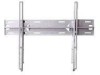
Wall plate B. Leveling feet (88.9) (31.75) (606.92) (49.53) (127) Page 16 (36.91) Figure 16 Installation Manual PWM-F110 Technical Specifications (406.4) (406.4) (711.2) (406.4) A. Mounting brackets C. ¼" x 20 Safety screws D.
Wall plate B. Leveling feet (88.9) (31.75) (606.92) (49.53) (127) Page 16 (36.91) Figure 16 Installation Manual PWM-F110 Technical Specifications (406.4) (406.4) (711.2) (406.4) A. Mounting brackets C. ¼" x 20 Safety screws D.