
Owner's Manual
Page 4
...cords 13 Digital audio coaxial cords/ Optical cables 13 Connecting digital components 14 Connecting audio components 15 Connecting DVD 5.1 channel components ... 16 Connecting video components 16 Connecting to the front panel video terminal 17 Connecting antennas 18 FM wire antenna 18 AM loop antenna ... FM reception 18 To improve AM reception 18 Connecting the speakers 19 Speaker terminals 20 A and B speaker systems 20 Hints on speaker placement 20 Connecting additional amplifiers 22 AC outlet 23 Operating other Pioneer components .......... 23 4 Controls and displays Front ...
...cords 13 Digital audio coaxial cords/ Optical cables 13 Connecting digital components 14 Connecting audio components 15 Connecting DVD 5.1 channel components ... 16 Connecting video components 16 Connecting to the front panel video terminal 17 Connecting antennas 18 FM wire antenna 18 AM loop antenna ... FM reception 18 To improve AM reception 18 Connecting the speakers 19 Speaker terminals 20 A and B speaker systems 20 Hints on speaker placement 20 Connecting additional amplifiers 22 AC outlet 23 Operating other Pioneer components .......... 23 4 Controls and displays Front ...
Owner's Manual
Page 6
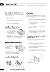
... voltages. Operating range of this unit. If this happens, the magnetic field produced by the transformers in this unit (as leakage and bursting. Making cable connections Make sure not to leave more than 8 inches (20 cm.) of batteries may result in such hazards as shown in the illustration). Loading the batteries...
... voltages. Operating range of this unit. If this happens, the magnetic field produced by the transformers in this unit (as leakage and bursting. Making cable connections Make sure not to leave more than 8 inches (20 cm.) of batteries may result in such hazards as shown in the illustration). Loading the batteries...

Owner's Manual
Page 8
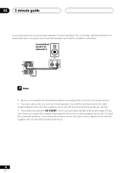
...'t need to do this with the following quick setup guide, you should refer to Optical digital input setting on page 41 to assign the optical input to DVD. Use a video cord to connect the video output on your system hooked up your receiver to the TV using a optical cable, see Optical digital... input settings on page 41 to assign the optical input to DVD. Optical cable Note: If you hook up using an optical...
...'t need to do this with the following quick setup guide, you should refer to Optical digital input setting on page 41 to assign the optical input to DVD. Use a video cord to connect the video output on your system hooked up your receiver to the TV using a optical cable, see Optical digital... input settings on page 41 to assign the optical input to DVD. Optical cable Note: If you hook up using an optical...

Owner's Manual
Page 9
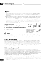
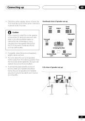
... E R S R FRONT L B AC OUTLET One Surround Back Speaker (or passive SW subwoofer) TV INPUT Powered subwoofer Be sure to complete all connections before connecting this case the center speaker shown is best. Make sure you 're not using a subwoofer, change the front speaker setting (see Speaker setting on ...the left terminal. Simply connect the speakers you have in the diagram) but everyone's home setup will work with a nominal impedance of eight speakers is shown ...
... E R S R FRONT L B AC OUTLET One Surround Back Speaker (or passive SW subwoofer) TV INPUT Powered subwoofer Be sure to complete all connections before connecting this case the center speaker shown is best. Make sure you 're not using a subwoofer, change the front speaker setting (see Speaker setting on ...the left terminal. Simply connect the speakers you have in the diagram) but everyone's home setup will work with a nominal impedance of eight speakers is shown ...
Owner's Manual
Page 10
...• If you select subwoofer (SB SUBWF) in the Surround back speaker setting (see page 37) you only have one surround back speaker, connect the positive wire to the right channel (+) terminal, and the negative wire to the left channel (-) terminal. 10 En 02 5 minute guide If... you can hook up a subwoofer instead of speakers to the left channel (-) terminal (shown above , connecting the positive wire to the right channel (+) terminal, and the negative wire to the surround back speaker terminals. Surround back speaker (or subwoofer) R SURROUND...
...• If you select subwoofer (SB SUBWF) in the Surround back speaker setting (see page 37) you only have one surround back speaker, connect the positive wire to the right channel (+) terminal, and the negative wire to the left channel (-) terminal. 10 En 02 5 minute guide If... you can hook up a subwoofer instead of speakers to the left channel (-) terminal (shown above , connecting the positive wire to the right channel (+) terminal, and the negative wire to the surround back speaker terminals. Surround back speaker (or subwoofer) R SURROUND...

Owner's Manual
Page 13
...completely. R L VIDEO Component video cords Use component video cords to get clearer picture reproduction than regular video cords. In this receiver. Be sure to connect the monitor TV. Digital audio coaxial cord (or standard video cord) Optical cable 13 En S-video cables Use S-video cables (not supplied) to ... off the power and disconnect the power cord from the component video jacks on the rear of the TV is avoided. Connect from an S-video jack on the rear of the receiver to insert completely. Y Green Blue P B P R Red Digital audio coaxial cords/ Optical cables ...
...completely. R L VIDEO Component video cords Use component video cords to get clearer picture reproduction than regular video cords. In this receiver. Be sure to connect the monitor TV. Digital audio coaxial cord (or standard video cord) Optical cable 13 En S-video cables Use S-video cables (not supplied) to ... off the power and disconnect the power cord from the component video jacks on the rear of the TV is avoided. Connect from an S-video jack on the rear of the receiver to insert completely. Y Green Blue P B P R Red Digital audio coaxial cords/ Optical cables ...

Owner's Manual
Page 14
... surround sound is a matter of connections is the same but since some digital components only have an LD player, you need to do this is set correctly (optical or coaxial depending on your digital components to the rear panel as well. The VSX-41 has four digital inputs (two coaxial... inputs and two optical inputs). We also recommend hooking up your digital components to analog audio jacks as shown below. See page 17 to connect the front panel optical input. VIDEO (CD) ø ...
... surround sound is a matter of connections is the same but since some digital components only have an LD player, you need to do this is set correctly (optical or coaxial depending on your digital components to the rear panel as well. The VSX-41 has four digital inputs (two coaxial... inputs and two optical inputs). We also recommend hooking up your digital components to analog audio jacks as shown below. See page 17 to connect the front panel optical input. VIDEO (CD) ø ...

Owner's Manual
Page 15
... to hook up four plugs to the receiver (a set of stereo inputs and a set of stereo outputs), but for more on digital connections. When connecting your analog audio components (such as a cassette deck) to hook up one set of the audio signal. The arrows indicate the direction ... jacks. CD player CD-R/Tape/MD Deck OUTPUT L R REC PLAY L R DIGITA ASSIG IN AUX DVD 7.1CH INPUT CENTER SUB W. Connecting up 03 Connecting audio components To begin set up, connect your equipment, always make sure the power is turned off and the power cord is disconnected from analog components.
... to hook up four plugs to the receiver (a set of stereo inputs and a set of stereo outputs), but for more on digital connections. When connecting your analog audio components (such as a cassette deck) to hook up one set of the audio signal. The arrows indicate the direction ... jacks. CD player CD-R/Tape/MD Deck OUTPUT L R REC PLAY L R DIGITA ASSIG IN AUX DVD 7.1CH INPUT CENTER SUB W. Connecting up 03 Connecting audio components To begin set up, connect your equipment, always make sure the power is turned off and the power cord is disconnected from analog components.

Owner's Manual
Page 16
... LOOP FM UNBAL IN 75 Ω IN IN IN R AUDIO DIGITAL IN COAX OPT OPT ASSIGNABLE AUX DVD 7.1CH INPUT CENTER SUB W. However, you are connecting only has one surround back channel output, change the Surround back channel input setting (page 40) to the jacks as shown below. When... (quality descends in order to hear a digital source (like a DVD) you should hook up the audio to hook up using the same kind of the connections shown on the rear of the receiver instead of the regular video jacks (see the second illustration of this order) on the next page for...
... LOOP FM UNBAL IN 75 Ω IN IN IN R AUDIO DIGITAL IN COAX OPT OPT ASSIGNABLE AUX DVD 7.1CH INPUT CENTER SUB W. However, you are connecting only has one surround back channel output, change the Surround back channel input setting (page 40) to the jacks as shown below. When... (quality descends in order to hear a digital source (like a DVD) you should hook up the audio to hook up using the same kind of the connections shown on the rear of the receiver instead of the regular video jacks (see the second illustration of this order) on the next page for...

Owner's Manual
Page 17
... REC INPUT CD-R IN / TAPE / MD PLAY L MONITOR OUT SUB WOOFER PREOUT IN TV/ SAT DVD / IN LD CONTROL OUT E A KA E R S Connecting to the front panel video terminal Front video connections are standard audio/video jacks as well as VIDEO. TV tuner (or Satellite tuner) OUTPUT VIDEO L R DVD or LD player OUTPUT... R AUDIO DIGITAL IN COAX OPT OPT ASSIGNABLE AUX DVD 7.1CH INPUT CENTER SUB W. Hook them up 03 The arrows indicate the direction of the signal. Connecting up the same way you made the rear panel...
... REC INPUT CD-R IN / TAPE / MD PLAY L MONITOR OUT SUB WOOFER PREOUT IN TV/ SAT DVD / IN LD CONTROL OUT E A KA E R S Connecting to the front panel video terminal Front video connections are standard audio/video jacks as well as VIDEO. TV tuner (or Satellite tuner) OUTPUT VIDEO L R DVD or LD player OUTPUT... R AUDIO DIGITAL IN COAX OPT OPT ASSIGNABLE AUX DVD 7.1CH INPUT CENTER SUB W. Hook them up 03 The arrows indicate the direction of the signal. Connecting up the same way you made the rear panel...

Owner's Manual
Page 18
... along a window frame or other suitable area, etc. FM UNBAL 75Ω 75 Ω coaxial cable FM ANTENNA To improve AM reception Connect a 15-18 feet length of vinyl-coated wire to the receiver. Always make sure that gives the best reception. Attach to a wall, ...10mm) AM LOOP ANTENNA Using external antennas To improve FM reception Connect an external FM antenna. To improve reception and sound quality, connect external antennas (see Using external antennas below . AM loop antenna Assemble the antenna and connect to the AM antenna terminal without disconnecting the supplied AM loop...
... along a window frame or other suitable area, etc. FM UNBAL 75Ω 75 Ω coaxial cable FM ANTENNA To improve AM reception Connect a 15-18 feet length of vinyl-coated wire to the receiver. Always make sure that gives the best reception. Attach to a wall, ...10mm) AM LOOP ANTENNA Using external antennas To improve FM reception Connect an external FM antenna. To improve reception and sound quality, connect external antennas (see Using external antennas below . AM loop antenna Assemble the antenna and connect to the AM antenna terminal without disconnecting the supplied AM loop...

Owner's Manual
Page 19
... L B AC OUTLET One Surround Back Speaker (or passive SW subwoofer) INPUT Powered subwoofer TV Be sure to complete all connections before connecting this unit to large. If you connect the speaker on the right to the right terminal and the speaker on the left to the left terminal. Also make sure... source. 19 En ASSIGNABLE (DVD/ LD) IN ¥ CD (DVD/ LD)¥ S - Connecting up 03 Connecting the speakers A complete setup of 8 Ω to 16 Ω. Simply connect the speakers you have in the diagram) but everyone's home setup will vary. The receiver will work ...
... L B AC OUTLET One Surround Back Speaker (or passive SW subwoofer) INPUT Powered subwoofer TV Be sure to complete all connections before connecting this unit to large. If you connect the speaker on the right to the right terminal and the speaker on the left to the left terminal. Also make sure... source. 19 En ASSIGNABLE (DVD/ LD) IN ¥ CD (DVD/ LD)¥ S - Connecting up 03 Connecting the speakers A complete setup of 8 Ω to 16 Ω. Simply connect the speakers you have in the diagram) but everyone's home setup will vary. The receiver will work ...
Owner's Manual
Page 20
...be placed on placement that all the bare speaker wire is the main system supporting the full speaker setup. others should be audible. Connect the positive wire to the right channel (+) terminal, and the negative wire to the left channel (-) terminal (see illustration on both..., if you choose just the B system you are using magnetically shielded speakers to prevent possible interference, such as the center speaker (C), connect the CENTER PREOUT jack on this case the center speaker shown is switched on page 10). Speaker terminals 1 Twist exposed wire strands together...
...be placed on placement that all the bare speaker wire is the main system supporting the full speaker setup. others should be audible. Connect the positive wire to the right channel (+) terminal, and the negative wire to the left channel (-) terminal (see illustration on both..., if you choose just the B system you are using magnetically shielded speakers to prevent possible interference, such as the center speaker (C), connect the CENTER PREOUT jack on this case the center speaker shown is switched on page 10). Speaker terminals 1 Twist exposed wire strands together...
Owner's Manual
Page 21
... sure to secure it with putty, or by other suitable means, to reduce the risk of the center channel is localized at the TV screen. Connecting up 21 En Be sure all speakers are installed securely to place the surround speakers further away from the TV in the event of external...
... sure to secure it with putty, or by other suitable means, to reduce the risk of the center channel is localized at the TV screen. Connecting up 21 En Be sure all speakers are installed securely to place the surround speakers further away from the TV in the event of external...

Owner's Manual
Page 22
... amplifiers This receiver has more than sufficient power for any home use, however it is switched off and unplugged from the pre-outs, disconnect any connections. The arrows indicate the direction of the audio signal. IN ANTENNA IN OPT AUX (TV/ SAT) ¥ (/CTDA-PREC/ Dø / ...changing any speakers that the receiver is possible to add additional amplifiers to power your speakers. Make the connections shown below to add amplifiers to every channel. Always make sure that are connected directly to the receiver. • If you're not using a subwoofer, change the front speaker...
... amplifiers This receiver has more than sufficient power for any home use, however it is switched off and unplugged from the pre-outs, disconnect any connections. The arrows indicate the direction of the audio signal. IN ANTENNA IN OPT AUX (TV/ SAT) ¥ (/CTDA-PREC/ Dø / ...changing any speakers that the receiver is possible to add additional amplifiers to power your speakers. Make the connections shown below to add amplifiers to every channel. Always make sure that are connected directly to the receiver. • If you're not using a subwoofer, change the front speaker...

Owner's Manual
Page 23
...the power cord once in order to avoid overheating and fire risk. OUT CONTROL CONTROL IN OUT Receiver Other Pioneer products with a control terminal Remote control unit Connect to CONTROL IN terminal of other cords. This can point the remote controls of this unit, and sent...power consumption to the AC WALL OUTLET in a while. Operating other Pioneer components By connecting a control cord (optional), you can also cause the receiver to malfunction. Do not connect appliances with a control terminal 23 En Connecting up 03 AC wall outlet [switched 100 W (0.8 A) max] ...
...the power cord once in order to avoid overheating and fire risk. OUT CONTROL CONTROL IN OUT Receiver Other Pioneer products with a control terminal Remote control unit Connect to CONTROL IN terminal of other cords. This can point the remote controls of this unit, and sent...power consumption to the AC WALL OUTLET in a while. Operating other Pioneer components By connecting a control cord (optional), you can also cause the receiver to malfunction. Do not connect appliances with a control terminal 23 En Connecting up 03 AC wall outlet [switched 100 W (0.8 A) max] ...

Owner's Manual
Page 24
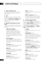
...modes. 6 MASTER VOLUME 7 PHONES jack Use to switch between the various Pro Logic II options. ADVANCED SURROUND (pages 31, 33) Use to connect headphones. Use it to select options after pressing TONE CONTROL, QUICK SETUP or TUNER EDIT. 8 STATION (+/-) buttons (pages 44-45) Selects station... the tuner. 10 LISTENING MODE buttons STANDARD (pages 30, 32,33) Press for the most accurate reproduction of tasks. When the headphones are connected, there is in standby. 3 Remote sensor Receives the signals from the speakers. 04 Controls and Displays Front panel 1 2 STANDBY STANDBY/ON ...
...modes. 6 MASTER VOLUME 7 PHONES jack Use to switch between the various Pro Logic II options. ADVANCED SURROUND (pages 31, 33) Use to connect headphones. Use it to select options after pressing TONE CONTROL, QUICK SETUP or TUNER EDIT. 8 STATION (+/-) buttons (pages 44-45) Selects station... the tuner. 10 LISTENING MODE buttons STANDARD (pages 30, 32,33) Press for the most accurate reproduction of tasks. When the headphones are connected, there is in standby. 3 Remote sensor Receives the signals from the speakers. 04 Controls and Displays Front panel 1 2 STANDBY STANDBY/ON ...

Owner's Manual
Page 27
... so that the remote is in Setup mode so that the remote is transmitting control signals. 4 CHARACTER display (LCD) Shows function modes and other components connected to default settings (see page 49). LEARN ERASE 3 SEARCH BY BRAND 4 1 SOURCE Press to turn on/off other information.
... so that the remote is in Setup mode so that the remote is transmitting control signals. 4 CHARACTER display (LCD) Shows function modes and other components connected to default settings (see page 49). LEARN ERASE 3 SEARCH BY BRAND 4 1 SOURCE Press to turn on/off other information.
Owner's Manual
Page 28
... surround sound of the receiver. INPUT ATT, FL. ACCESS (page 43) After pressing, you have selected the corresponding MULTI CONTROL button (TUNER or DVD (when connected to control a component after you have selected it isn't possible to prevent distortion (when the overload indicator lights). D. LEVEL +/- (page 42) Adjusts the levels of...
... surround sound of the receiver. INPUT ATT, FL. ACCESS (page 43) After pressing, you have selected the corresponding MULTI CONTROL button (TUNER or DVD (when connected to control a component after you have selected it isn't possible to prevent distortion (when the overload indicator lights). D. LEVEL +/- (page 42) Adjusts the levels of...

Owner's Manual
Page 32
... and shows in the display. 32 En If the source is AUTO. Each press switches between input signals. To prevent noise, make the proper digital connections (page 14) and set the signal input to the source component. SOURCE RECEIVER LEARN ERASE SEARCH BY BRAND DVD TV VCR CD-R MULTI CONTROL RCV...
... and shows in the display. 32 En If the source is AUTO. Each press switches between input signals. To prevent noise, make the proper digital connections (page 14) and set the signal input to the source component. SOURCE RECEIVER LEARN ERASE SEARCH BY BRAND DVD TV VCR CD-R MULTI CONTROL RCV...


