

User Manual
Page 1
HDF550F 5 HP 24 Inch Tiller • Assembly • Operation • Customer Responsibilities • Service and Adjustments • Storage • Troubleshooting • Repair Parts For Parts and Service, contact our authorized distributor: call 1-800-849-1297 For Technical Assistance: call 1-800-829-5886 Poulan 163659 11.13.97 TR PRINTED IN U.S.A. xx Ve44*4+04, rya OWNER'S MANUAL (Q° MODEL NO.
HDF550F 5 HP 24 Inch Tiller • Assembly • Operation • Customer Responsibilities • Service and Adjustments • Storage • Troubleshooting • Repair Parts For Parts and Service, contact our authorized distributor: call 1-800-849-1297 For Technical Assistance: call 1-800-829-5886 Poulan 163659 11.13.97 TR PRINTED IN U.S.A. xx Ve44*4+04, rya OWNER'S MANUAL (Q° MODEL NO.

User Manual
Page 2
...; Check shear pins, engine mounting bolts, and other bolts at high speeds on slippery surfaces. • Handle fuel with care; CAUTION: Always disconnect spark plug wire and place wire where it is generally a warning of the tiller (such as hot water and space heaters, clothes dryers, and the like ). • Never operate the tiller without proper guards, plates, or other reproductive harm. 2 Allow the engine to prevent accidental starting . Wear...
...; Check shear pins, engine mounting bolts, and other bolts at high speeds on slippery surfaces. • Handle fuel with care; CAUTION: Always disconnect spark plug wire and place wire where it is generally a warning of the tiller (such as hot water and space heaters, clothes dryers, and the like ). • Never operate the tiller without proper guards, plates, or other reproductive harm. 2 Allow the engine to prevent accidental starting . Wear...
User Manual
Page 3
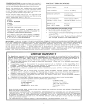
..., abuse, improper assembly or installation, delivery damage, or to service or repair this Warranty, please contact: American Yard Products Service Department P.O. MODEL NUMBER HDF550F SERIAL NUMBER DATE OF PURCHASE THE MODEL AND SERIAL NUMBERS WILL BE FOUND ON THE MODEL PLATE ATTACHED TO THE RIGHT HAND ENGINE BRACKET. IF A SPARK ARRESTER IS USED, IT SHOULD BE MAINTAINED IN EFFECTIVE WORKING ORDER BY THE OPERATOR. This Warranty is a limited Warranty within the meaning...
..., abuse, improper assembly or installation, delivery damage, or to service or repair this Warranty, please contact: American Yard Products Service Department P.O. MODEL NUMBER HDF550F SERIAL NUMBER DATE OF PURCHASE THE MODEL AND SERIAL NUMBERS WILL BE FOUND ON THE MODEL PLATE ATTACHED TO THE RIGHT HAND ENGINE BRACKET. IF A SPARK ARRESTER IS USED, IT SHOULD BE MAINTAINED IN EFFECTIVE WORKING ORDER BY THE OPERATOR. This Warranty is a limited Warranty within the meaning...

User Manual
Page 4
... SPECIFICATIONS WARRANTY ASSEMBLY OPERATION 2 3, 11-13 3 3 5-6 7-10 MAINTENANCE SCHEDULE SERVICE & ADJUSTMENTS STORAGE TROUBLESHOOTING REPAIR PARTS-TILLER 11 13-16 17 18 19-24 INDEX A Adjustments: Carburetor Depth Stake Handle Height Tines V-Belt Wheels Air Cleaner B Belt, V-: Belt Guard Repair Parts V-Belt Replacement C Cooling System Controls: Choke Throttle Tines Cultivating Customer Responsibilities: Air Cleaner Cooling System Finish Maintenance Schedule Muffler Oil Change Spark Plug Transmission D Depth Stake: Adjustment Repair Parts E Engine: Air Cleaner Cooling System Fuel Type...
... SPECIFICATIONS WARRANTY ASSEMBLY OPERATION 2 3, 11-13 3 3 5-6 7-10 MAINTENANCE SCHEDULE SERVICE & ADJUSTMENTS STORAGE TROUBLESHOOTING REPAIR PARTS-TILLER 11 13-16 17 18 19-24 INDEX A Adjustments: Carburetor Depth Stake Handle Height Tines V-Belt Wheels Air Cleaner B Belt, V-: Belt Guard Repair Parts V-Belt Replacement C Cooling System Controls: Choke Throttle Tines Cultivating Customer Responsibilities: Air Cleaner Cooling System Finish Maintenance Schedule Muffler Oil Change Spark Plug Transmission D Depth Stake: Adjustment Repair Parts E Engine: Air Cleaner Cooling System Fuel Type...

User Manual
Page 6
... of cartoning material. LOCK NUT WASHER TILLER HANDLE HANDLE PANEL 49 0 FLAT WASHER HEX BOLT 5/16-18X1" HEX BOLT 5116-18X3/4" CABLE TILLER HANDLES HANDLE PANEL BOLTS 0 UPPER REVERSE ROD COTTER PIN 0 CLEVIS PIN INSTALL DEPTH STAKE ASSEMBLY (See Fig. 3) • Loosen nut "A" . • Insert stake support between engine bracket halves with stake spring down. • Bolt stake support to better suit operator. (See "HANDLE HEIGHT in the Service and Adjustments section of this manual). Tighten securely...
... of cartoning material. LOCK NUT WASHER TILLER HANDLE HANDLE PANEL 49 0 FLAT WASHER HEX BOLT 5/16-18X1" HEX BOLT 5116-18X3/4" CABLE TILLER HANDLES HANDLE PANEL BOLTS 0 UPPER REVERSE ROD COTTER PIN 0 CLEVIS PIN INSTALL DEPTH STAKE ASSEMBLY (See Fig. 3) • Loosen nut "A" . • Insert stake support between engine bracket halves with stake spring down. • Bolt stake support to better suit operator. (See "HANDLE HEIGHT in the Service and Adjustments section of this manual). Tighten securely...
User Manual
Page 7
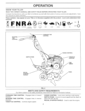
Engages tines in forward direction. CHOKE CONTROL - Learn and understand their meaning. Controls engine speed. REVERSE TINE CONTROL - Controls forward speed and the depth at which the tiller will dig. OPERATION KNOW YOUR TILLER READ THIS OWNER'S MANUAL AND SAFETY RULES BEFORE OPERATING YOUR TILLER. Save this manual for future reference. FORWARD TINE CONTROL - Used when starting a cold engine. THROTTLE CONTROL - Engages tines in reverse direction. RECOIL STARTER HANDLE - Used to familiarize yourself with the product...
Engages tines in forward direction. CHOKE CONTROL - Learn and understand their meaning. Controls engine speed. REVERSE TINE CONTROL - Controls forward speed and the depth at which the tiller will dig. OPERATION KNOW YOUR TILLER READ THIS OWNER'S MANUAL AND SAFETY RULES BEFORE OPERATING YOUR TILLER. Save this manual for future reference. FORWARD TINE CONTROL - Used when starting a cold engine. THROTTLE CONTROL - Engages tines in reverse direction. RECOIL STARTER HANDLE - Used to familiarize yourself with the product...
User Manual
Page 8
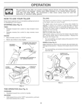
... throttle control to "STOP" position. • Never use choke to start engine. Change depth stake to penetrate the ground. Replace the clevis pin and hairpin clip. • For normal tilling, set wheels at the second or third hole from the top. WHEELS (See Fig. 6) Adjust wheels by the poSition of the depth stake and wheel height. Always wear safety glasses or eye shields before adding fuel and oil or...
... throttle control to "STOP" position. • Never use choke to start engine. Change depth stake to penetrate the ground. Replace the clevis pin and hairpin clip. • For normal tilling, set wheels at the second or third hole from the top. WHEELS (See Fig. 6) Adjust wheels by the poSition of the depth stake and wheel height. Always wear safety glasses or eye shields before adding fuel and oil or...

User Manual
Page 9
... the recoil starter to move choke control to cool. When starting engine. • To change oil fog easier starting (See "OIL VISCOSITY CHART" in upright position to be emptied before engaging tines. Grasp recoil starter handle with one hand and grasp tiller OIL LEVEL handle with oil to point of fuel tank to prevent spills and to allow tiller engine and muffler to OIL FILLER PLUG half choke position. tures (below 32°F), the carburetor fuel mixture may occur...
... the recoil starter to move choke control to cool. When starting engine. • To change oil fog easier starting (See "OIL VISCOSITY CHART" in upright position to be emptied before engaging tines. Grasp recoil starter handle with one hand and grasp tiller OIL LEVEL handle with oil to point of fuel tank to prevent spills and to allow tiller engine and muffler to OIL FILLER PLUG half choke position. tures (below 32°F), the carburetor fuel mixture may occur...

User Manual
Page 10
... this manual. First, wide turns are important for five minutes. • Check tine operation and adjust if necessary. At the same time, breaking up and down the rows at normal depth. eN FIG. 10 10 To slow down the tiller, press down and engage tine control to start actual field use the depth stake. A properly adjusted tiller will dig with throttle in slow position...
... this manual. First, wide turns are important for five minutes. • Check tine operation and adjust if necessary. At the same time, breaking up and down the rows at normal depth. eN FIG. 10 10 To slow down the tiller, press down and engage tine control to start actual field use the depth stake. A properly adjusted tiller will dig with throttle in slow position...

User Manual
Page 11
CUSTOMER RESPONSIBILITIES MAINTENANCE SCHEDULE FILL IN DATES AS YOU COMPLETE REGULAR SERVICE 44/ ,. co O) co o o 47. (4, -z--',
CUSTOMER RESPONSIBILITIES MAINTENANCE SCHEDULE FILL IN DATES AS YOU COMPLETE REGULAR SERVICE 44/ ,. co O) co o o 47. (4, -z--',

User Manual
Page 12
... 25 hours in increased oil consumption when used to clean or dry cartridge. Check the crankcase oil level before starting in very dusty conditions. • Loosen air cleaner screws, one year. Remove fuel from running low on each time you check the oil level. ENGINE LUBRICATION Use only high quality detergent oil rated with oil. MUFFLER CYLINDER FINS BLOWER HOUSING OIL DRAIN PLUG AIR SCREEN OIL FILLER PLUG OIL LEVEL FIG. 12 12 0 FIG. 14 AIR CLEANER (See Fig. 13) Service air cleaner cartridge every twenty...
... 25 hours in increased oil consumption when used to clean or dry cartridge. Check the crankcase oil level before starting in very dusty conditions. • Loosen air cleaner screws, one year. Remove fuel from running low on each time you check the oil level. ENGINE LUBRICATION Use only high quality detergent oil rated with oil. MUFFLER CYLINDER FINS BLOWER HOUSING OIL DRAIN PLUG AIR SCREEN OIL FILLER PLUG OIL LEVEL FIG. 12 12 0 FIG. 14 AIR CLEANER (See Fig. 13) Service air cleaner cartridge every twenty...

User Manual
Page 13
... tilling or cultivating needs. Water in engine can be different when tiller digs into contact with a spark arrester screen assembly, remove every 50 hours for your unit unless the muffler, air filter and carburetor are sharp. a CAUTION: Tines are covered to desired location. • Tighten the four nuts securely. Inspect periodically and replace if necessary. Spark plug type and gap setting are shown in a shortened engine life. TILLER TO ADJUST HANDLE HEIGHT (See Fig...
... tilling or cultivating needs. Water in engine can be different when tiller digs into contact with a spark arrester screen assembly, remove every 50 hours for your unit unless the muffler, air filter and carburetor are sharp. a CAUTION: Tines are covered to desired location. • Tighten the four nuts securely. Inspect periodically and replace if necessary. Spark plug type and gap setting are shown in a shortened engine life. TILLER TO ADJUST HANDLE HEIGHT (See Fig...

User Manual
Page 14
... belt guard. • Loosen (do not remove) tine shield nut on underside of fuel to the engine giving a leaner fuel/air mixture. However, minor adjustments may result. In general, turning the idle needle valve in bottom of belt guard is factory adjusted. Make final adjustments with engine running at the factory and adjustment should not be assembled to die, then turn valve out (counterclockwise) 1-1/2 turns. Turn valve to "FAST" position. If the carburetor does need adjustment, proceed as follows. Release throttle...
... belt guard. • Loosen (do not remove) tine shield nut on underside of fuel to the engine giving a leaner fuel/air mixture. However, minor adjustments may result. In general, turning the idle needle valve in bottom of belt guard is factory adjusted. Make final adjustments with engine running at the factory and adjustment should not be assembled to die, then turn valve out (counterclockwise) 1-1/2 turns. Turn valve to "FAST" position. If the carburetor does need adjustment, proceed as follows. Release throttle...

User Manual
Page 15
... carburetor. ACIDIC GAS CAN DAMAGE THE FUEL SYSTEM OF AN ENGINE WHILE IN STORAGE. • Drain the fuel tank. • Start the engine and let it to give protection from one season to another. • Replace your gasoline can if your can starts to rust. Run engine at the end of oil through spark plug hole into cylinder. • Pull starter handle slowly several times to distribute oil. • Replace with clean oil. (See "ENGINE...
... carburetor. ACIDIC GAS CAN DAMAGE THE FUEL SYSTEM OF AN ENGINE WHILE IN STORAGE. • Drain the fuel tank. • Start the engine and let it to give protection from one season to another. • Replace your gasoline can if your can starts to rust. Run engine at the end of oil through spark plug hole into cylinder. • Pull starter handle slowly several times to distribute oil. • Replace with clean oil. (See "ENGINE...

User Manual
Page 16
...Spark plug wire loose. 10. Dirty engine air screen. 11. Connect and tighten spark plug wire. 10. Clean/replace muffler. 12. Check oil level/change oil. 4. Clean engine air screen. 3. Adjust carburetor to start. 4. Carburetor out of power 1. Engage tine control. 2. Inspect V-belt. • • . 1. Water in "FAST" position. 2. Bad spark plug or improper gap. 9. Fill fuel tank. 2. Drain fuel tank and carburetor, and refill tank with fresh gasoline. 8. Remove fuel tank and clean. 7. Drain fuel tank and refill with fresh gasoline. 7. Make sure spark plug wire...
...Spark plug wire loose. 10. Dirty engine air screen. 11. Connect and tighten spark plug wire. 10. Clean/replace muffler. 12. Check oil level/change oil. 4. Clean engine air screen. 3. Adjust carburetor to start. 4. Carburetor out of power 1. Engage tine control. 2. Inspect V-belt. • • . 1. Water in "FAST" position. 2. Bad spark plug or improper gap. 9. Fill fuel tank. 2. Drain fuel tank and carburetor, and refill tank with fresh gasoline. 8. Remove fuel tank and clean. 7. Drain fuel tank and refill with fresh gasoline. 7. Make sure spark plug wire...
User Manual
Page 17
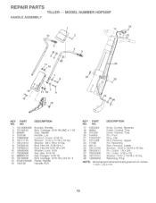
.... 5/16-18 x 1 Bolt, Hex Hd 5/16-18 x 3/4 Washer, Lock 5/16 Nut, Hex 5/16-18 Nut, Flanged 5/16-18 Bolt, Carriage 5/16-18 x 3/4 Gr. 5 Panel, Handle Handle, R.H. Control, Tine Pin, Pivot Ring, Klip Rod, Reverse, Upper Pin, Retaining Rod, Reverse, Lower Washer 13/32 x 13/16 x 16 Ga. inches. 1 inch-. 25.4 mm 19 Washer 3/8 x 7/8 x 14 Ga. NO. MODEL NUMBER HDF550F HANDLE ASSEMBLY 2 4 3 19 18 \ ,:'„17 i-20 214-29 zt...
.... 5/16-18 x 1 Bolt, Hex Hd 5/16-18 x 3/4 Washer, Lock 5/16 Nut, Hex 5/16-18 Nut, Flanged 5/16-18 Bolt, Carriage 5/16-18 x 3/4 Gr. 5 Panel, Handle Handle, R.H. Control, Tine Pin, Pivot Ring, Klip Rod, Reverse, Upper Pin, Retaining Rod, Reverse, Lower Washer 13/32 x 13/16 x 16 Ga. inches. 1 inch-. 25.4 mm 19 Washer 3/8 x 7/8 x 14 Ga. NO. MODEL NUMBER HDF550F HANDLE ASSEMBLY 2 4 3 19 18 \ ,:'„17 i-20 214-29 zt...
User Manual
Page 18
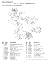
REPAIR PARTS TILLER - - MODEL NUMBER HDF550F BELT GUARD AND PULLEY ASSEMBLY 2 3 6 7 30 31 17 te( 29 *"..'.. .....'N. .... 'Ns:4. ..s • ..... *N., '` ''''. %..'N.,... ' '''.: s• 71 '', ...'z.,.., ,27 28 ; -----, 8 29 1 9 .. '--..,,,, 33 1124 ,'1-•••1••,•1._' rr) 26 4:144' • 4:11 34 19 10 1 11 12 13 14 15 0 '.1; 16 23 22 21 32 18 KEY PART NO. Cutting #10-24 x 1/2 Type D Bolt, Hex 1/2-20 x 3/4 Nut, Hex 3/8-16 Washer 13/32...
REPAIR PARTS TILLER - - MODEL NUMBER HDF550F BELT GUARD AND PULLEY ASSEMBLY 2 3 6 7 30 31 17 te( 29 *"..'.. .....'N. .... 'Ns:4. ..s • ..... *N., '` ''''. %..'N.,... ' '''.: s• 71 '', ...'z.,.., ,27 28 ; -----, 8 29 1 9 .. '--..,,,, 33 1124 ,'1-•••1••,•1._' rr) 26 4:144' • 4:11 34 19 10 1 11 12 13 14 15 0 '.1; 16 23 22 21 32 18 KEY PART NO. Cutting #10-24 x 1/2 Type D Bolt, Hex 1/2-20 x 3/4 Nut, Hex 3/8-16 Washer 13/32...

User Manual
Page 19
... 7 4921H 8 1952J 9 122233X 10 326J 11 74780628 12 74760524 13 1951J DESCRIPTION Pin, Clevis Bolt, Hex 5/16-18 x 1-1/4 Bolt, Hex 5/16-18 x 3/4 Nut, Hex 5/16-18 Washer, Lock 5/16 Locknut, w/washer 3/8-16 Clip, Hairpin Support, Depth Stake, R.H. inches. 1 inch = 25.4 mm 21 KEY PART NO. MODEL NUMBER HDF550F WHEEL AND DEPTH STAKE ASSEMBLY 16 17 2 ti„ 2 3 I I. NO. 14 120958X 15 5388J 16 121117X...
... 7 4921H 8 1952J 9 122233X 10 326J 11 74780628 12 74760524 13 1951J DESCRIPTION Pin, Clevis Bolt, Hex 5/16-18 x 1-1/4 Bolt, Hex 5/16-18 x 3/4 Nut, Hex 5/16-18 Washer, Lock 5/16 Locknut, w/washer 3/8-16 Clip, Hairpin Support, Depth Stake, R.H. inches. 1 inch = 25.4 mm 21 KEY PART NO. MODEL NUMBER HDF550F WHEEL AND DEPTH STAKE ASSEMBLY 16 17 2 ti„ 2 3 I I. NO. 14 120958X 15 5388J 16 121117X...
User Manual
Page 21
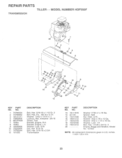
... 20 DESCRIPTION Washer 17/32 x1 x 16 Ga. inches. 1 inch = 25.4 mm 23 Washer, Lock 5/16 Nut, Hex 5/16-18 Bolt, Hex 5/16-18 x 2-3/4 Transmission KEY PART NO. Washer, Lock 1/4 Bolt, Hex 1/4-28 x 3/4 Gr. 5 Engine, Briggs and Stratton, Model No. 137202 • NOTE: All component dimensions given in U.S. MODEL NUMBER HDF550F TRANSMISSION 3 3 5 6 9 z 7 0 14 1 14 13 8 0 90 14 1 12 KEY PART NO. NO. 1 74760524 2 74780652 3 19131311 5 73800600 6 9057R428...
... 20 DESCRIPTION Washer 17/32 x1 x 16 Ga. inches. 1 inch = 25.4 mm 23 Washer, Lock 5/16 Nut, Hex 5/16-18 Bolt, Hex 5/16-18 x 2-3/4 Transmission KEY PART NO. Washer, Lock 1/4 Bolt, Hex 1/4-28 x 3/4 Gr. 5 Engine, Briggs and Stratton, Model No. 137202 • NOTE: All component dimensions given in U.S. MODEL NUMBER HDF550F TRANSMISSION 3 3 5 6 9 z 7 0 14 1 14 13 8 0 90 14 1 12 KEY PART NO. NO. 1 74760524 2 74780652 3 19131311 5 73800600 6 9057R428...
User Manual
Page 22
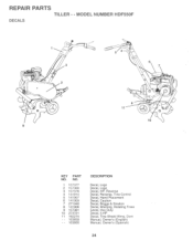
MODEL NUMBER HDF550F DECALS 0 0 0 0 0 0 2 0 O 5 4 0 8 11 KEY PART NO. REPAIR PARTS TILLER - - NO. 1 157377 2 157380 3 157378 4 141914 5 141907 6 141909 7 271948 8 141906 9 157381 10 273721 11 162215 - - 163659 - - 163660 DESCRIPTION Decal, Logo Decal, Logo Decal, HP, Reverse Decal, Reverse, Tine Control Decal, Hand Placement Decal, Caution Decal, Briggs & Strattdn Decal, Warning, Rotating Tines Decal, Hvy Duty Decal, 5 HP Decal, Tine Shield Wrng. Dom Manual, Owner's (English) Manual, Owner's (Spanish) 24
MODEL NUMBER HDF550F DECALS 0 0 0 0 0 0 2 0 O 5 4 0 8 11 KEY PART NO. REPAIR PARTS TILLER - - NO. 1 157377 2 157380 3 157378 4 141914 5 141907 6 141909 7 271948 8 141906 9 157381 10 273721 11 162215 - - 163659 - - 163660 DESCRIPTION Decal, Logo Decal, Logo Decal, HP, Reverse Decal, Reverse, Tine Control Decal, Hand Placement Decal, Caution Decal, Briggs & Strattdn Decal, Warning, Rotating Tines Decal, Hvy Duty Decal, 5 HP Decal, Tine Shield Wrng. Dom Manual, Owner's (English) Manual, Owner's (Spanish) 24


