
User Manual
Page 2
... objects. 2. Never allow adults to make any adjustments while the engine (motor) is highly flammable (f) Keep the nozzle in moving parts. it cannot contact plug in the manual(s) before filling. 4. Never attempt to operate the equipment without wearing adequate winter garments. If...areas. Disengage all times, until refueling is spilled on slippery surfaces. 4. Do not put hands or feet near or under rotating parts. containers on contact, stay away from your vehicle, before operating this symbol to a running (except when specifically recommended by the ...
... objects. 2. Never allow adults to make any adjustments while the engine (motor) is highly flammable (f) Keep the nozzle in moving parts. it cannot contact plug in the manual(s) before filling. 4. Never attempt to operate the equipment without wearing adequate winter garments. If...areas. Disengage all times, until refueling is spilled on slippery surfaces. 4. Do not put hands or feet near or under rotating parts. containers on contact, stay away from your vehicle, before operating this symbol to a running (except when specifically recommended by the ...
User Manual
Page 3
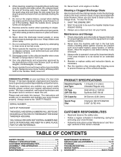
...SCHEDULE 14 PRODUCT SPECIFICATIONS 3 SERVICE AND ADJUSTMENTS 16-18 CUSTOMER RESPONSIBILITIES 3 STORAGE 19 ASSEMBLY / PRE-OPERATION 4-7 TROUBLESHOOTING 20 OPERATION 8-13 REPAIR PARTS 21-39 MAINTENANCE 14-15 3 WARRANTY BACK PAGE Open the outside doors; Never operate the machine at too fast a rate. 12. ...HOUSING. When cleaning, repairing or inspecting the snow thrower, stop the engine and make certain the collector/impeller and all moving parts have competent, well-trained technicians and the proper tools to prevent freeze-up of a new snow thrower. never run the...
...SCHEDULE 14 PRODUCT SPECIFICATIONS 3 SERVICE AND ADJUSTMENTS 16-18 CUSTOMER RESPONSIBILITIES 3 STORAGE 19 ASSEMBLY / PRE-OPERATION 4-7 TROUBLESHOOTING 20 OPERATION 8-13 REPAIR PARTS 21-39 MAINTENANCE 14-15 3 WARRANTY BACK PAGE Open the outside doors; Never operate the machine at too fast a rate. 12. ...HOUSING. When cleaning, repairing or inspecting the snow thrower, stop the engine and make certain the collector/impeller and all moving parts have competent, well-trained technicians and the proper tools to prevent freeze-up of a new snow thrower. never run the...

User Manual
Page 4
... four corners of carton and lay panels flat. 3. Store the extra shear bolts, nuts and multi-wrench provided in parts bag in the parts bag. Cut down all packing materials except plastic tie holding speed control rod to assemble or operate your snow thrower. ...plastic ties securing the upper handle to the pallet. 4. Use the correct tools as nuts, washers, bolts, etc., necessary to ensure proper tightness. 2. PARTS PACKED SEPARATELY IN CARTON (1) FUEL STABILIZER PACKET (1) MULTIWRENCH (180684) (1) POWER CORD (198563) SAFTEY IGNITION KEY(S) (193071) (1) AUGER CONTROL ROD (1) ...
... four corners of carton and lay panels flat. 3. Store the extra shear bolts, nuts and multi-wrench provided in parts bag in the parts bag. Cut down all packing materials except plastic tie holding speed control rod to assemble or operate your snow thrower. ...plastic ties securing the upper handle to the pallet. 4. Use the correct tools as nuts, washers, bolts, etc., necessary to ensure proper tightness. 2. PARTS PACKED SEPARATELY IN CARTON (1) FUEL STABILIZER PACKET (1) MULTIWRENCH (180684) (1) POWER CORD (198563) SAFTEY IGNITION KEY(S) (193071) (1) AUGER CONTROL ROD (1) ...

User Manual
Page 5
... rod into speed control bracket and secure with retainer spring. Use to secure upper handle to lower handle. 2. Insert rod into hole in bag of parts. With top end of rod positioned under left side of control panel, push rod down and insert top end of the chute rotator head to...
... rod into speed control bracket and secure with retainer spring. Use to secure upper handle to lower handle. 2. Insert rod into hole in bag of parts. With top end of rod positioned under left side of control panel, push rod down and insert top end of the chute rotator head to...

User Manual
Page 6
... BRACKET TIGHTENING LOCKNUT FIG. 7 ROTATOR HEAD MOUNTING BRACKET AUGER CONTROL BRACKET FIG. 6 6 Secure with loop opening toward front of chute base with holes in your parts bag may be used to align square and pin on underside of mounting bracket. 4. If necessary, rotate chute assembly to install the chute rotator head... discharge opening up as shown. (See Fig. 5) 3. With chute rotator head and chute bracket aligned, position chute rotator head on rod and insert end of parts and retrieve the auger control rod from bag of rod into control arm with retainer spring.
... BRACKET TIGHTENING LOCKNUT FIG. 7 ROTATOR HEAD MOUNTING BRACKET AUGER CONTROL BRACKET FIG. 6 6 Secure with loop opening toward front of chute base with holes in your parts bag may be used to align square and pin on underside of mounting bracket. 4. If necessary, rotate chute assembly to install the chute rotator head... discharge opening up as shown. (See Fig. 5) 3. With chute rotator head and chute bracket aligned, position chute rotator head on rod and insert end of parts and retrieve the auger control rod from bag of rod into control arm with retainer spring.

User Manual
Page 10
... and/or auger. Do not use . Keep the area of operation clear of all persons, small children and pets at all moving parts to disengage. Always wear safety glasses or eye shields while operating 00155 your snow thrower or performing any snow thrower can result in severe...back to throw snow a short distance; OFF FULL FIG. 11 TO CONTROL SNOW DISCHARGE (See Fig. 12) WARNING: Snow throwers have exposed rotating parts, which snow is to start the engine. STOPPING TRACTION DRIVE • Release traction drive control lever to raise the deflector and increase the distance. ...
... and/or auger. Do not use . Keep the area of operation clear of all persons, small children and pets at all moving parts to disengage. Always wear safety glasses or eye shields while operating 00155 your snow thrower or performing any snow thrower can result in severe...back to throw snow a short distance; OFF FULL FIG. 11 TO CONTROL SNOW DISCHARGE (See Fig. 12) WARNING: Snow throwers have exposed rotating parts, which snow is to start the engine. STOPPING TRACTION DRIVE • Release traction drive control lever to raise the deflector and increase the distance. ...

User Manual
Page 11
... of the snow thrower, is pointed in a safe direction (no vehicles, buildings, people, or other objects are disengaged and the auger/impeller and all moving parts have stopped. It is engaged.
... of the snow thrower, is pointed in a safe direction (no vehicles, buildings, people, or other objects are disengaged and the auger/impeller and all moving parts have stopped. It is engaged.

User Manual
Page 14
... belts for loose fasteners. 3. A new spark plug will need to slow leaks, tire sealant may be replaced by original equipment manufacturer local parts dealer. LUBRICATION Keep your engine run better and last longer. • Follow the maintenance schedule in both tires (14-17 P.S.I. ). •... of special construction to be sure they begin to properly maintain your nearest dealer. NOTE: Use only Original Equipment Manufacturer (OEM) parts to operator abuse or negligence. Replace belts if they are not adjustable. Check controls to be made periodically to slip from your ...
... belts for loose fasteners. 3. A new spark plug will need to slow leaks, tire sealant may be replaced by original equipment manufacturer local parts dealer. LUBRICATION Keep your engine run better and last longer. • Follow the maintenance schedule in both tires (14-17 P.S.I. ). •... of special construction to be sure they begin to properly maintain your nearest dealer. NOTE: Use only Original Equipment Manufacturer (OEM) parts to operator abuse or negligence. Replace belts if they are not adjustable. Check controls to be made periodically to slip from your ...

User Manual
Page 16
... substitute. Remove belt cover. • Replace belt cover by installing cover and screws and tighten securely. Make sure the augers and all moving parts to any service or adjustments: 1. Should a foreign object or ice become lodged in auger hub with two (2) capscrew/shear bolts and hex ...with spark plug. 3. Remove safety ignition key and disconnect spark plug wire from spark plug. CAUTION: Do not substitute. Disengage all moving parts to see if the capscrews have sheared. Place wire where it should be replaced. Install 1/4-20 lock nut and tighten securely. Wait for...
... substitute. Remove belt cover. • Replace belt cover by installing cover and screws and tighten securely. Make sure the augers and all moving parts to any service or adjustments: 1. Should a foreign object or ice become lodged in auger hub with two (2) capscrew/shear bolts and hex ...with spark plug. 3. Remove safety ignition key and disconnect spark plug wire from spark plug. CAUTION: Do not substitute. Disengage all moving parts to see if the capscrews have sheared. Place wire where it should be replaced. Install 1/4-20 lock nut and tighten securely. Wait for...
User Manual
Page 18
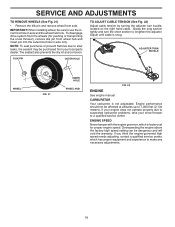
... be sure to use the innermost hole in axle only. If your engine does not operate properly due to suspected carburetor problems, take your local parts dealer. ADJUSTER TURN BUCKLE WHEEL FIG. 21 INNER HOLE WHEEL HUB FIG. 22 ENGINE See engine manual. SERVICE AND ADJUSTMENTS TO REMOVE WHEELS (See Fig...
... be sure to use the innermost hole in axle only. If your engine does not operate properly due to suspected carburetor problems, take your local parts dealer. ADJUSTER TURN BUCKLE WHEEL FIG. 21 INNER HOLE WHEEL HUB FIG. 22 ENGINE See engine manual. SERVICE AND ADJUSTMENTS TO REMOVE WHEELS (See Fig...
User Manual
Page 19
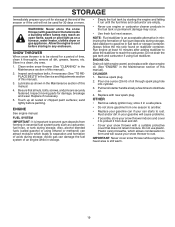
... starting the engine and letting it from forming in fuel tank or storage container. Inspect moving parts for damage, breakage and wear. Pull recoil starter handle slowly a few times to gasoline in essential fuel system parts such as on stabilizer container. Rust and/or dirt in a safe place. • Do not store...
... starting the engine and letting it from forming in fuel tank or storage container. Inspect moving parts for damage, breakage and wear. Pull recoil starter handle slowly a few times to gasoline in essential fuel system parts such as on stabilizer container. Rust and/or dirt in a safe place. • Do not store...

User Manual
Page 20
... / reinstall auger belt. 2. Spark plug wire is covered with fresh, clean gasoline. 4. Fill fuel tank with ice or snow. 4. Fuel tank cap is disconnected. 9. Loose parts or damaged augers or impeller. 1. Throttle in fuel line. 3. Move choke to FULL position. 6. Blockage in STOP position (or ON/OFF switch is OFF). 5. Check... belt. 3. Wait a few minutes before restarting, DO NOT prime. 8. Dirty or clogged muffler. 1. Clean or replace muffler. Contact an authorized service center/department. Replace damaged parts.
... / reinstall auger belt. 2. Spark plug wire is covered with fresh, clean gasoline. 4. Fill fuel tank with ice or snow. 4. Fuel tank cap is disconnected. 9. Loose parts or damaged augers or impeller. 1. Throttle in fuel line. 3. Move choke to FULL position. 6. Blockage in STOP position (or ON/OFF switch is OFF). 5. Check... belt. 3. Wait a few minutes before restarting, DO NOT prime. 8. Dirty or clogged muffler. 1. Clean or replace muffler. Contact an authorized service center/department. Replace damaged parts.

User Manual
Page 21
...Manufacturer (O.E.M.) replacement parts. MODEL PP115E27 (96198004000) AUGER HOUSING / IMPELLER ASSEMBLY 1 3 (5x) 4 (5x) 2 01.07.002-A KEY NO. 1 2 3 4 PART NO. 404929X428 404932X431 72270505 155377 DESCRIPTION AUGER HOUSING 27 SCRAPER BAR CARRIAGE BOLT 5/16−18 X .625 NUT 5/16−18 2 1 KEY NO. 1 2 PART NO. 420495X421 ...420496X421 DESCRIPTION AUGER 27 LH AUGER 27 RH 01.07.018-A NOTE: All component dimensions given in U.S. REPAIR PARTS SNOW THROWER - Failure to do so could be hazardous, damage your snow ...
...Manufacturer (O.E.M.) replacement parts. MODEL PP115E27 (96198004000) AUGER HOUSING / IMPELLER ASSEMBLY 1 3 (5x) 4 (5x) 2 01.07.002-A KEY NO. 1 2 3 4 PART NO. 404929X428 404932X431 72270505 155377 DESCRIPTION AUGER HOUSING 27 SCRAPER BAR CARRIAGE BOLT 5/16−18 X .625 NUT 5/16−18 2 1 KEY NO. 1 2 PART NO. 420495X421 ...420496X421 DESCRIPTION AUGER 27 LH AUGER 27 RH 01.07.018-A NOTE: All component dimensions given in U.S. REPAIR PARTS SNOW THROWER - Failure to do so could be hazardous, damage your snow ...

User Manual
Page 22
Failure to do so could be hazardous, damage your snow thrower and void your warranty. 22 MODEL PP115E27 (96198004000) AUGER HOUSING / IMPELLER ASSEMBLY 5 15 14 4 11 6 11 16 12 13 11 3 12 10 11 7 8 17 1 9 37 2 9 9 33 37 32 34 30 31 31 29 28 26 27 36 20 21 22 23 25 35 24 23 22 21 18 19 2 (EXPLODED) 01.07.026-D NOTE: All component dimensions given in U.S. inches. 1 inch = 25.4 mm IMPORTANT: Use only Original Equipment Manufacturer (O.E.M.) replacement parts. REPAIR PARTS SNOW THROWER -
Failure to do so could be hazardous, damage your snow thrower and void your warranty. 22 MODEL PP115E27 (96198004000) AUGER HOUSING / IMPELLER ASSEMBLY 5 15 14 4 11 6 11 16 12 13 11 3 12 10 11 7 8 17 1 9 37 2 9 9 33 37 32 34 30 31 31 29 28 26 27 36 20 21 22 23 25 35 24 23 22 21 18 19 2 (EXPLODED) 01.07.026-D NOTE: All component dimensions given in U.S. inches. 1 inch = 25.4 mm IMPORTANT: Use only Original Equipment Manufacturer (O.E.M.) replacement parts. REPAIR PARTS SNOW THROWER -

User Manual
Page 23
... IMPORTANT: Use only Original Equipment Manufacturer (O.E.M.) replacement parts. MODEL PP115E27 (96198004000) AUGER HOUSING / IMPELLER ASSEMBLY KEY NO. 1 2 3 4 5 6 7 8 9 10 11 12 13 14 15 16 17 18 19 20 21 22 23 24 25 26 27 28 29 30 31 32 33 34 35 36 37 PART NO. 175321X431 427148 188909 427146 175322 178675X431... SHEAR BOLT NOTE: All component dimensions given in U.S. Failure to do so could be hazardous, damage your snow thrower and void your warranty. 23 REPAIR PARTS SNOW THROWER -
... IMPORTANT: Use only Original Equipment Manufacturer (O.E.M.) replacement parts. MODEL PP115E27 (96198004000) AUGER HOUSING / IMPELLER ASSEMBLY KEY NO. 1 2 3 4 5 6 7 8 9 10 11 12 13 14 15 16 17 18 19 20 21 22 23 24 25 26 27 28 29 30 31 32 33 34 35 36 37 PART NO. 175321X431 427148 188909 427146 175322 178675X431... SHEAR BOLT NOTE: All component dimensions given in U.S. Failure to do so could be hazardous, damage your snow thrower and void your warranty. 23 REPAIR PARTS SNOW THROWER -

User Manual
Page 24
... snow thrower and void your warranty. 24 inches. 1 inch = 25.4 mm IMPORTANT: Use only Original Equipment Manufacturer (O.E.M.) replacement parts. REPAIR PARTS SNOW THROWER - MODEL PP115E27 (96198004000) AUGER HOUSING / IMPELLER ASSEMBLY 2 3 1 1 2 3 01.07.024-B KEY NO. 1 2 3 PART NO. 420478 411939 179582 DESCRIPTION AUGER BEARING BEARING PLUG SCREW 5/16−18 X 1.00 4 4 01.11.001-B 3 1 3 2 KEY...
... snow thrower and void your warranty. 24 inches. 1 inch = 25.4 mm IMPORTANT: Use only Original Equipment Manufacturer (O.E.M.) replacement parts. REPAIR PARTS SNOW THROWER - MODEL PP115E27 (96198004000) AUGER HOUSING / IMPELLER ASSEMBLY 2 3 1 1 2 3 01.07.024-B KEY NO. 1 2 3 PART NO. 420478 411939 179582 DESCRIPTION AUGER BEARING BEARING PLUG SCREW 5/16−18 X 1.00 4 4 01.11.001-B 3 1 3 2 KEY...
User Manual
Page 25
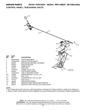
MODEL PP115E27 (96198004000) CONTROL PANEL / DISCHARGE CHUTE 5 7 15 3 16 *14 *11 2 4 6 *10 KEY PART 6 NO. ITEMS 15 AND 16 ARE SERVICE PART NUMBERS TO ALLOW PURCHASE OF INDIVIDUAL ITEMS IF NECESSARY. inches. 1 inch = 25.4 mm IMPORTANT: Use only Original Equipment Manufacturer (O.E.M.) replacement parts. ALL ...625 *13 751153 NUT 5/16-18 *14 184505 DEFLECTOR SPRING 15 420679 (SERVICE PART) DEFLECTOR CONTROL 16 420672 (SERVICE PART) DEFLECTOR CABLE BLACK *13 *12 9 8 01.09.015-B NOTE: 1. REPAIR PARTS SNOW THROWER - NO. Failure to do so could be hazardous, damage your snow...
MODEL PP115E27 (96198004000) CONTROL PANEL / DISCHARGE CHUTE 5 7 15 3 16 *14 *11 2 4 6 *10 KEY PART 6 NO. ITEMS 15 AND 16 ARE SERVICE PART NUMBERS TO ALLOW PURCHASE OF INDIVIDUAL ITEMS IF NECESSARY. inches. 1 inch = 25.4 mm IMPORTANT: Use only Original Equipment Manufacturer (O.E.M.) replacement parts. ALL ...625 *13 751153 NUT 5/16-18 *14 184505 DEFLECTOR SPRING 15 420679 (SERVICE PART) DEFLECTOR CONTROL 16 420672 (SERVICE PART) DEFLECTOR CABLE BLACK *13 *12 9 8 01.09.015-B NOTE: 1. REPAIR PARTS SNOW THROWER - NO. Failure to do so could be hazardous, damage your snow...
User Manual
Page 26
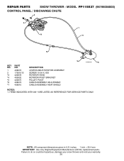
inches. 1 inch = 25.4 mm IMPORTANT: Use only Original Equipment Manufacturer (O.E.M.) replacement parts. REPAIR PARTS SNOW THROWER - ITEMS INDICATED WITH AN * ARE LISTED AS REFERENCE FOR SERVICE PARTS ONLY. MODEL PP115E27 (96198004000) CONTROL PANEL / DISCHARGE CHUTE 2 2 *3 1 *7 *6 KEY NO. 1 2 *3 *4 *5 *6 *7 PART NO. 428272 17501010 420678 405932 420675 428273 428310 DESCRIPTION LEVER/CABLE ROTATOR ASSEMBLY SCREW 10-24 X .625 ROTATOR...
inches. 1 inch = 25.4 mm IMPORTANT: Use only Original Equipment Manufacturer (O.E.M.) replacement parts. REPAIR PARTS SNOW THROWER - ITEMS INDICATED WITH AN * ARE LISTED AS REFERENCE FOR SERVICE PARTS ONLY. MODEL PP115E27 (96198004000) CONTROL PANEL / DISCHARGE CHUTE 2 2 *3 1 *7 *6 KEY NO. 1 2 *3 *4 *5 *6 *7 PART NO. 428272 17501010 420678 405932 420675 428273 428310 DESCRIPTION LEVER/CABLE ROTATOR ASSEMBLY SCREW 10-24 X .625 ROTATOR...
User Manual
Page 27
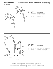
MODEL PP115E27 (96198004000) 4 4 3 2 3 4 4 3 3 KEY PART NO. NO. DESCRIPTION 1 419797X431 LOWER HANDLE 4 2 427513X431 PIVOT SUPPORT WELDMENT 3 428867 SCREW 5/16−18 X .750 4 17000616 SCREW 3/8−16 X 1.00 3 4 3 4 4 01-05-013-A NOTE: All component dimensions given in U.S. REPAIR PARTS HANDLES SNOW THROWER - inches. 1 inch = 25.4 mm IMPORTANT: Use only Original Equipment Manufacturer (O.E.M.) replacement parts. NO. DESCRIPTION 1 419798X431...
MODEL PP115E27 (96198004000) 4 4 3 2 3 4 4 3 3 KEY PART NO. NO. DESCRIPTION 1 419797X431 LOWER HANDLE 4 2 427513X431 PIVOT SUPPORT WELDMENT 3 428867 SCREW 5/16−18 X .750 4 17000616 SCREW 3/8−16 X 1.00 3 4 3 4 4 01-05-013-A NOTE: All component dimensions given in U.S. REPAIR PARTS HANDLES SNOW THROWER - inches. 1 inch = 25.4 mm IMPORTANT: Use only Original Equipment Manufacturer (O.E.M.) replacement parts. NO. DESCRIPTION 1 419798X431...

User Manual
Page 28
inches. 1 inch = 25.4 mm IMPORTANT: Use only Original Equipment Manufacturer (O.E.M.) replacement parts. MODEL PP115E27 (96198004000) 2 10 10 1 3 8 9 4 KEY NO. 1 2 3 4 5 6 7 8 9 10 PART NO. 180480 405740 180445 187716 180447 178669 180926 72270505 155377 169675 DESCRIPTION IMPELLER ROD TRACTION ROD SHIFTER ROD TOP SHIFTER ROD BOTTOM SPRING SLEEVE IMPELLER ....12.001-E NOTE: All component dimensions given in U.S. Failure to do so could be hazardous, damage your snow thrower and void your warranty. 28 REPAIR PARTS HANDLES SNOW THROWER -
inches. 1 inch = 25.4 mm IMPORTANT: Use only Original Equipment Manufacturer (O.E.M.) replacement parts. MODEL PP115E27 (96198004000) 2 10 10 1 3 8 9 4 KEY NO. 1 2 3 4 5 6 7 8 9 10 PART NO. 180480 405740 180445 187716 180447 178669 180926 72270505 155377 169675 DESCRIPTION IMPELLER ROD TRACTION ROD SHIFTER ROD TOP SHIFTER ROD BOTTOM SPRING SLEEVE IMPELLER ....12.001-E NOTE: All component dimensions given in U.S. Failure to do so could be hazardous, damage your snow thrower and void your warranty. 28 REPAIR PARTS HANDLES SNOW THROWER -


