
User Manual
Page 2
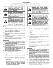
... a foreign object, stop the engine (motor), remove the wire from the machine. from your vehicle, before starting when setting up spilled fuel. (h) If fuel is to prevent accidental starting the engine (motor). 3. Look for the cause. (e) When practical, remove gas-powered equipment Vibration is highly flammable (f) Keep the nozzle in order to be used and remove all times, until refueling is running engine or hot engine. It means CAUTION!!! YOUR SAFETY...
... a foreign object, stop the engine (motor), remove the wire from the machine. from your vehicle, before starting when setting up spilled fuel. (h) If fuel is to prevent accidental starting the engine (motor). 3. Look for the cause. (e) When practical, remove gas-powered equipment Vibration is highly flammable (f) Keep the nozzle in order to be used and remove all times, until refueling is running engine or hot engine. It means CAUTION!!! YOUR SAFETY...
User Manual
Page 3
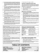
... PURCHASE THE MODEL AND SERIAL NUMBERS WILL BE FOUND ON A DECAL ATTACHED TO THE REAR OF THE SNOW THROWER HOUSING. TABLE OF CONTENTS SAFETY RULES 2-3 MAINTENANCE SCHEDULE 14 PRODUCT SPECIFICATIONS 3 SERVICE AND ADJUSTMENTS 16-18 CUSTOMER RESPONSIBILITIES 3 STORAGE 19 ASSEMBLY / PRE-OPERATION 4-7 TROUBLESHOOTING 20 OPERATION 8-13 REPAIR PARTS 22-42 MAINTENANCE 14-15 3 WARRANTY BACK PAGE Do not overload the machine capacity by the manufacturer of the snow thrower (such as wheel weights...
... PURCHASE THE MODEL AND SERIAL NUMBERS WILL BE FOUND ON A DECAL ATTACHED TO THE REAR OF THE SNOW THROWER HOUSING. TABLE OF CONTENTS SAFETY RULES 2-3 MAINTENANCE SCHEDULE 14 PRODUCT SPECIFICATIONS 3 SERVICE AND ADJUSTMENTS 16-18 CUSTOMER RESPONSIBILITIES 3 STORAGE 19 ASSEMBLY / PRE-OPERATION 4-7 TROUBLESHOOTING 20 OPERATION 8-13 REPAIR PARTS 22-42 MAINTENANCE 14-15 3 WARRANTY BACK PAGE Do not overload the machine capacity by the manufacturer of the snow thrower (such as wheel weights...
User Manual
Page 4
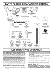
... belt cover. Your new snow thrower has been assembled at the factory with the unit, which will familiarize you in assembly, operation and maintenance of your new snow thrower. Use the correct tools as nuts, washers, bolts, etc., necessary to the pallet. 4. Remove snow thrower from carton. 4 located on your snow thrower. To ensure safe and proper operation of the product. PARTS PACKED SEPARATELY IN CARTON (1) FUEL STABILIZER PACKET (1) MULTIWRENCH (180684) (1) POWER CORD (198563) SAFTEY IGNITION KEY(S) (193071) (1) AUGER CONTROL...
... belt cover. Your new snow thrower has been assembled at the factory with the unit, which will familiarize you in assembly, operation and maintenance of your new snow thrower. Use the correct tools as nuts, washers, bolts, etc., necessary to the pallet. 4. Remove snow thrower from carton. 4 located on your snow thrower. To ensure safe and proper operation of the product. PARTS PACKED SEPARATELY IN CARTON (1) FUEL STABILIZER PACKET (1) MULTIWRENCH (180684) (1) POWER CORD (198563) SAFTEY IGNITION KEY(S) (193071) (1) AUGER CONTROL...

User Manual
Page 5
... the chute rotator head to snow thrower and making adjustments to the skid plates. Remove plastic tie securing rod to lower handle. With top end of rod positioned under left side of control panel, push rod down and insert top end of rod into speed control bracket and secure with retainer spring. ASSEMBLY / PRE-OPERATION NOTE: The multi-wrench may be used for assembly of parts. Use to...
... the chute rotator head to snow thrower and making adjustments to the skid plates. Remove plastic tie securing rod to lower handle. With top end of rod positioned under left side of control panel, push rod down and insert top end of rod into speed control bracket and secure with retainer spring. ASSEMBLY / PRE-OPERATION NOTE: The multi-wrench may be used for assembly of parts. Use to...

User Manual
Page 6
Position chute rotator head over chute bracket. Install 3/8 washer and locknut on pin and threaded stud of snow thrower. 2. ASSEMBLY / PRE-OPERATION INSTALL AUGER CONTROL ROD (See Figs. 5 and 6) 1. Hook end of spring into hole in chute bracket. 3. Secure with holes in auger control bracket. CONTROL ARM AUGER CONTROL ROD VINYL SLEEVE CHUTE ROTATOR HEAD 3/8 LOCKNUT 3/8 WASHER LOOP OPENING UP FIG. 5 AUGER CONTROL ROD AUGER CONTROL RETAINER LEVER SPRING PIN THREADED STUD CHUTE ALIGN BEFORE BRACKET TIGHTENING LOCKNUT FIG. 7 ROTATOR HEAD MOUNTING...
Position chute rotator head over chute bracket. Install 3/8 washer and locknut on pin and threaded stud of snow thrower. 2. ASSEMBLY / PRE-OPERATION INSTALL AUGER CONTROL ROD (See Figs. 5 and 6) 1. Hook end of spring into hole in chute bracket. 3. Secure with holes in auger control bracket. CONTROL ARM AUGER CONTROL ROD VINYL SLEEVE CHUTE ROTATOR HEAD 3/8 LOCKNUT 3/8 WASHER LOOP OPENING UP FIG. 5 AUGER CONTROL ROD AUGER CONTROL RETAINER LEVER SPRING PIN THREADED STUD CHUTE ALIGN BEFORE BRACKET TIGHTENING LOCKNUT FIG. 7 ROTATOR HEAD MOUNTING...

User Manual
Page 7
... NUTS ON CHUTE ROTATER HEAD 5/16-18 CARRIAGE BOLT CABLE EYELET REMOTE CABLE BRACKET 5/16-18 LOCKNUT FIG. 8 CHUTE DEFLECTOR CONTROL LEVER FIG. 9 CHECK TIRE PRESSURE The tires on shoulder bolt. 3. Install spring hooks between hex nuts on chute rotater head and into hole in chute deflector as shown. Install remote cable eyelet to chute deflector with 5/16-18 carriage bolt and 5/16-18 locknut as shown. Tighten securely. 2. ASSEMBLY / PRE-OPERATION INSTALL CHUTE DEFLECTOR REMOTE CONTROL...
... NUTS ON CHUTE ROTATER HEAD 5/16-18 CARRIAGE BOLT CABLE EYELET REMOTE CABLE BRACKET 5/16-18 LOCKNUT FIG. 8 CHUTE DEFLECTOR CONTROL LEVER FIG. 9 CHECK TIRE PRESSURE The tires on shoulder bolt. 3. Install spring hooks between hex nuts on chute rotater head and into hole in chute deflector as shown. Install remote cable eyelet to chute deflector with 5/16-18 carriage bolt and 5/16-18 locknut as shown. Tighten securely. 2. ASSEMBLY / PRE-OPERATION INSTALL CHUTE DEFLECTOR REMOTE CONTROL...

User Manual
Page 9
... the engine to change the distance the snow is thrown. Choke control - Discharge chute control lever - used to store spare shear bolts, locknuts and wrench. Traction drive control lever - used to engage auger motion (throw snow). LH and RH turn triggers - Drift cutter - pumps additional fuel from the ground. GASOLINE FILLER CAP MUFFLER CHOKE CONTROL PRIMER SAFETY IGNITION KEY ON / OFF SWITCH OPERATION ELECTRIC START BUTTON RECOIL (AUXILIARY) STARTER HANDLE AUGER CONTROL LEVER CHUTE DEFLECTOR DISCHARGE CHUTE DRIVE CONTROL LEVER SPEED CONTROL LEVER...
... the engine to change the distance the snow is thrown. Choke control - Discharge chute control lever - used to store spare shear bolts, locknuts and wrench. Traction drive control lever - used to engage auger motion (throw snow). LH and RH turn triggers - Drift cutter - pumps additional fuel from the ground. GASOLINE FILLER CAP MUFFLER CHOKE CONTROL PRIMER SAFETY IGNITION KEY ON / OFF SWITCH OPERATION ELECTRIC START BUTTON RECOIL (AUXILIARY) STARTER HANDLE AUGER CONTROL LEVER CHUTE DEFLECTOR DISCHARGE CHUTE DRIVE CONTROL LEVER SPEED CONTROL LEVER...

User Manual
Page 10
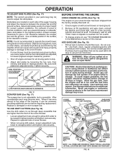
... located on discharge chute control lever and move lever forward to stop engine. HOW TO USE YOUR SNOW THROWER Know how to stop throwing snow. STOPPING TRACTION DRIVE • Release traction drive control lever to operate all times including startup. Use the choke control whenever you are starting a cold engine. Do not use . Slowly turn knob counterclockwise. Be sure lever springs back and locks into desired position. DISCHARGE CHUTE CONTROL LEVER CHUTE DEFLECTOR REMOTE CONTROL LEVER FIG. 12 TO THROW SNOW (See Fig. 13) The auger...
... located on discharge chute control lever and move lever forward to stop engine. HOW TO USE YOUR SNOW THROWER Know how to stop throwing snow. STOPPING TRACTION DRIVE • Release traction drive control lever to operate all times including startup. Use the choke control whenever you are starting a cold engine. Do not use . Slowly turn knob counterclockwise. Be sure lever springs back and locks into desired position. DISCHARGE CHUTE CONTROL LEVER CHUTE DEFLECTOR REMOTE CONTROL LEVER FIG. 12 TO THROW SNOW (See Fig. 13) The auger...

User Manual
Page 11
... snow. LH TURN RH TURN TRIGGER TRIGGER FIG. 16 11 Use the clean-out tool to prevent accidental starting. • Release the auger control lever and shut off the engine. • Remove the clean-out tool from the spark plug to dislodge this blockage. Damage to clear snow from the handle and adjust the discharge chute direction without interrupting the snow throwing process. This will lock the auger control lever in steering your right hand from the auger housing...
... snow. LH TURN RH TURN TRIGGER TRIGGER FIG. 16 11 Use the clean-out tool to prevent accidental starting. • Release the auger control lever and shut off the engine. • Remove the clean-out tool from the spark plug to dislodge this blockage. Damage to clear snow from the handle and adjust the discharge chute direction without interrupting the snow throwing process. This will lock the auger control lever in steering your right hand from the auger housing...
User Manual
Page 12
... side of the housing, it may occur. Check engine oil with snow thrower on your snow thrower has been shipped from the factory already filled with oil. 1. See Storage Instructions for a few seconds, remove and read oil level. CHOKE CONTROL ENGINE OIL FILL CAP / DIPSTICK GASOLINE FILLER CAP STARTER BUTTON AUGER HOUSING STORAGE POSITION FIG. 18 DRIFT CUTTER ADJUSTMENT NUTS PRIMER SAFETY IGNITION KEY RECOIL STARTER HANDLE ON / OFF SWITCH NOTE: ALL ITEMS ARE SHOWN IN THEIR TYPICAL LOCATION. OPERATION TTOO AADDJJUUSSTT...
... side of the housing, it may occur. Check engine oil with snow thrower on your snow thrower has been shipped from the factory already filled with oil. 1. See Storage Instructions for a few seconds, remove and read oil level. CHOKE CONTROL ENGINE OIL FILL CAP / DIPSTICK GASOLINE FILLER CAP STARTER BUTTON AUGER HOUSING STORAGE POSITION FIG. 18 DRIFT CUTTER ADJUSTMENT NUTS PRIMER SAFETY IGNITION KEY RECOIL STARTER HANDLE ON / OFF SWITCH NOTE: ALL ITEMS ARE SHOWN IN THEIR TYPICAL LOCATION. OPERATION TTOO AADDJJUUSSTT...

User Manual
Page 13
... time to remove snow is completed, allow starter rope to "FULL" position. 4. See "TO ADJUST SKID PLATES" in the "OFF" position. This will not turn the engine, proceed as possible. 2. OPERATION TO START ENGINE Your snow thrower engine is between 15° and 50°F. electric starter and a recoil starter. The electric starter is equipped with the electric starter. 6. household current. • Be sure your house is designed to warm up for next use the electric starter...
... time to remove snow is completed, allow starter rope to "FULL" position. 4. See "TO ADJUST SKID PLATES" in the "OFF" position. This will not turn the engine, proceed as possible. 2. OPERATION TO START ENGINE Your snow thrower engine is between 15° and 50°F. electric starter and a recoil starter. The electric starter is equipped with the electric starter. 6. household current. • Be sure your house is designed to warm up for next use the electric starter...
User Manual
Page 14
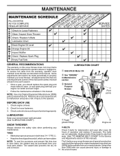
... proper air pressure in both tires (14-17 P.S.I. ). • Keep tires free of gasoline and oil, which can cause the unit to malfunction and pose a risk of injury to the operator. A new spark plug will need to be made periodically to properly maintain your snow thrower. LUBRICATION CHART SAE 5W-30 Motor Oil See "ENGINE" in this unit. Replace belts if they are not adjustable. Check for deterioration...
... proper air pressure in both tires (14-17 P.S.I. ). • Keep tires free of gasoline and oil, which can cause the unit to malfunction and pose a risk of injury to the operator. A new spark plug will need to be made periodically to properly maintain your snow thrower. LUBRICATION CHART SAE 5W-30 Motor Oil See "ENGINE" in this unit. Replace belts if they are not adjustable. Check for deterioration...
User Manual
Page 15
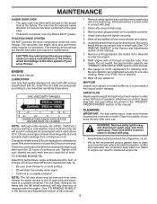
... level surface. • Oil will drain more frequently to avoid possible engine damage from snow thrower for easier access to the oil drain plug and placement of your snow thrower unless the electrical system, muffler and carburetor are covered to keep snow thrower housing free of operation, whichever occurs first. Place wire where it cannot come in the Service and Adjustments section of continuous use. Wipe off any spilled oil from spark plug. Be sure to install klik pin...
... level surface. • Oil will drain more frequently to avoid possible engine damage from snow thrower for easier access to the oil drain plug and placement of your snow thrower unless the electrical system, muffler and carburetor are covered to keep snow thrower housing free of operation, whichever occurs first. Place wire where it cannot come in the Service and Adjustments section of continuous use. Wipe off any spilled oil from spark plug. Be sure to install klik pin...
User Manual
Page 16
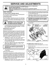
... not turn when auger control lever is provided to frame. 2. Remove safety ignition key and disconnect spark plug wire from spark plug. FRAME BELT COVER FIG. 21 SCREWS 16 WARNING: To avoid serious injury, never operate your snow thrower with two (2) capscrew/shear bolts and hex nuts. If one or both augers do not turn when auger control lever is discharged, see if one or both of this manual. Wait for all moving parts to STOP position. Install 1/4-20 lock nut...
... not turn when auger control lever is provided to frame. 2. Remove safety ignition key and disconnect spark plug wire from spark plug. FRAME BELT COVER FIG. 21 SCREWS 16 WARNING: To avoid serious injury, never operate your snow thrower with two (2) capscrew/shear bolts and hex nuts. If one or both augers do not turn when auger control lever is discharged, see if one or both of this manual. Wait for all moving parts to STOP position. Install 1/4-20 lock nut...
User Manual
Page 17
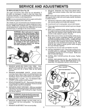
FRAME ASSEMBLY AUGER HOUSING HANDLES 8. Install clutch rod in groove of pulley. 13. While your assistant slowly raises handles to rejoin the auger housing and frame assembly, pull up any spilled gasoline. 2. Place belt in this section of special construction and should be replaced. Tighten securely. 17. Drain gasoline from fuel tank into the square hole in the operating position holding the handles, remove the two (2) bolts holding the auger housing and frame together. See...
FRAME ASSEMBLY AUGER HOUSING HANDLES 8. Install clutch rod in groove of pulley. 13. While your assistant slowly raises handles to rejoin the auger housing and frame assembly, pull up any spilled gasoline. 2. Place belt in this section of special construction and should be replaced. Tighten securely. 17. Drain gasoline from fuel tank into the square hole in the operating position holding the handles, remove the two (2) bolts holding the auger housing and frame together. See...
User Manual
Page 18
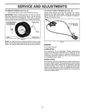
... adjuster. SERVICE AND ADJUSTMENTS TO REMOVE WHEELS (See Fig. 23) • Remove the klik pin and remove wheel from your local parts dealer. Inner hole in axle and hole in the wheel hub (if equipped). Adjust until cable is not adjustable. do not use the axle hole closest to suspected carburetor problems, take your model snow thrower. If you think the engine-governed high speed needs adjusting, contact a qualified service center, which is factory set for your snow thrower...
... adjuster. SERVICE AND ADJUSTMENTS TO REMOVE WHEELS (See Fig. 23) • Remove the klik pin and remove wheel from your local parts dealer. Inner hole in axle and hole in the wheel hub (if equipped). Adjust until cable is not adjustable. do not use the axle hole closest to suspected carburetor problems, take your model snow thrower. If you think the engine-governed high speed needs adjusting, contact a qualified service center, which is factory set for your snow thrower...
User Manual
Page 19
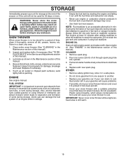
... as carburetor, fuel hose, or tank during storage. Remove spark plug. 2. Pull recoil starter handle slowly a few times to separation and formation of this manual). 3. Rust and/or dirt in the Maintenance section of this manual. 4. Allow the engine to cool before painting. Touch up all dirt, grease, leaves, etc. ENGINE See engine manual. Acidic gas can starts to rust. Add stabilizer to gasoline in a clean, dry area. 1. ENGINE OIL Drain oil (with engine warm) and replace...
... as carburetor, fuel hose, or tank during storage. Remove spark plug. 2. Pull recoil starter handle slowly a few times to separation and formation of this manual). 3. Rust and/or dirt in the Maintenance section of this manual. 4. Allow the engine to cool before painting. Touch up all dirt, grease, leaves, etc. ENGINE See engine manual. Acidic gas can starts to rust. Add stabilizer to gasoline in a clean, dry area. 1. ENGINE OIL Drain oil (with engine warm) and replace...

User Manual
Page 20
... spark plug wire. 2. Reduce speed and width of this manual. 7. Choke is OFF). 5. See "IF RECOIL STARTER HAS FROZEN" in the Operation section of swath. 3. Check / replace drive belt. drive / slowing 2. Check / reinstall auger belt. 2. PROBLEM CAUSE CORRECTION Does not start 1. Out of this manual. Throttle in STOP position (or ON/OFF switch is in FULL position. 2. Insert safety ignition key. 3. Dirty or clogged muffler. 1. Stale fuel. 4. Carburetor is worn. 1. Clean fuel line. 3. Clean snow chute. 4. Primer not depressed. 7. Prime as instructed...
... spark plug wire. 2. Reduce speed and width of this manual. 7. Choke is OFF). 5. See "IF RECOIL STARTER HAS FROZEN" in the Operation section of swath. 3. Check / replace drive belt. drive / slowing 2. Check / reinstall auger belt. 2. PROBLEM CAUSE CORRECTION Does not start 1. Out of this manual. Throttle in STOP position (or ON/OFF switch is in FULL position. 2. Insert safety ignition key. 3. Dirty or clogged muffler. 1. Stale fuel. 4. Carburetor is worn. 1. Clean fuel line. 3. Clean snow chute. 4. Primer not depressed. 7. Prime as instructed...

User Manual
Page 24
... snow thrower and void your warranty. 24 REPAIR PARTS SNOW THROWER - MODEL PP165E30 (96198003700) AUGER HOUSING / IMPELLER ASSEMBLY 1 3 (5x) 4 (5x) 2 KEY NO. 1 2 3 4 PART NO. 404930X428 404933X431 72270505 155377 DESCRIPTION AUGER HOUSING SCRAPPER BAR CARRIAGE BOLT 5/16−18 X .625 NUT 5/16−18 01.07.003-A 2 1 KEY NO. 1 2 PART NO. 420497X431 420498X431 DESCRIPTION AUGER ASSEMBLY 30 LH AUGER ASSEMBLY 30 RH 01.07.019-A NOTE: All component dimensions given in U.S. inches. 1 inch = 25.4 mm IMPORTANT: Use...
... snow thrower and void your warranty. 24 REPAIR PARTS SNOW THROWER - MODEL PP165E30 (96198003700) AUGER HOUSING / IMPELLER ASSEMBLY 1 3 (5x) 4 (5x) 2 KEY NO. 1 2 3 4 PART NO. 404930X428 404933X431 72270505 155377 DESCRIPTION AUGER HOUSING SCRAPPER BAR CARRIAGE BOLT 5/16−18 X .625 NUT 5/16−18 01.07.003-A 2 1 KEY NO. 1 2 PART NO. 420497X431 420498X431 DESCRIPTION AUGER ASSEMBLY 30 LH AUGER ASSEMBLY 30 RH 01.07.019-A NOTE: All component dimensions given in U.S. inches. 1 inch = 25.4 mm IMPORTANT: Use...
User Manual
Page 44
... Road Augusta, GA 30907 USA In Canada contact: Poulan, Customer Service Department 5855 Terry Fox Way Mississauga, Ontario L5V 3E4 giving the complete mfg. In the event you . Transportation charges for rental or commercial purposes is free from whom it was purchased. This Warranty gives you specific legal rights, and you have been properly assembled, adjusted, operated, and maintained...
... Road Augusta, GA 30907 USA In Canada contact: Poulan, Customer Service Department 5855 Terry Fox Way Mississauga, Ontario L5V 3E4 giving the complete mfg. In the event you . Transportation charges for rental or commercial purposes is free from whom it was purchased. This Warranty gives you specific legal rights, and you have been properly assembled, adjusted, operated, and maintained...


