
User Manual
Page 2
WARNING: Always disconnect spark plug wire and place it where it cannot contact plug in order to prevent accidental starting when setting up spilled fuel. (h) If fuel is spilled on clothing, change clothing immediately. 5. Do not use a nozzle lock-open device. (g) Replace gasoline cap securely and wipe up , transporting, adjusting or making any adjustments while the engine (motor) is complete. WARNING: Engine exhaust, some of its constituents, and certain...
WARNING: Always disconnect spark plug wire and place it where it cannot contact plug in order to prevent accidental starting when setting up spilled fuel. (h) If fuel is spilled on clothing, change clothing immediately. 5. Do not use a nozzle lock-open device. (g) Replace gasoline cap securely and wipe up , transporting, adjusting or making any adjustments while the engine (motor) is complete. WARNING: Engine exhaust, some of its constituents, and certain...

User Manual
Page 3
... MODEL AND SERIAL NUMBERS WILL BE FOUND ON A DECAL ATTACHED TO THE REAR OF THE SNOW THROWER HOUSING. Check shear bolts and other safety protective devices in maintaining, caring for proper tightness to service or repair this manual. TABLE OF CONTENTS SAFETY RULES 2-3 PRODUCT SPECIFICATIONS 3 CUSTOMER RESPONSIBILITIES 3 ASSEMBLY / PRE-OPERATION 4-7 OPERATION 8-13 MAINTENANCE SCHEDULE 14 MAINTENANCE 14-15 SERVICE AND ADJUSTMENTS 16-18 STORAGE 19 TROUBLESHOOTING 20 REPAIR PARTS 21-39 WARRANTY BACK COVER 3 PRODUCT SPECIFICATIONS Gasoline Capacity...
... MODEL AND SERIAL NUMBERS WILL BE FOUND ON A DECAL ATTACHED TO THE REAR OF THE SNOW THROWER HOUSING. Check shear bolts and other safety protective devices in maintaining, caring for proper tightness to service or repair this manual. TABLE OF CONTENTS SAFETY RULES 2-3 PRODUCT SPECIFICATIONS 3 CUSTOMER RESPONSIBILITIES 3 ASSEMBLY / PRE-OPERATION 4-7 OPERATION 8-13 MAINTENANCE SCHEDULE 14 MAINTENANCE 14-15 SERVICE AND ADJUSTMENTS 16-18 STORAGE 19 TROUBLESHOOTING 20 REPAIR PARTS 21-39 WARRANTY BACK COVER 3 PRODUCT SPECIFICATIONS Gasoline Capacity...

User Manual
Page 4
...) CHUTE DEFLECTOR REMOTE CONTROL (2) FLAT WASHERS (2) CARRIAGE BOLTS 3/8-16 x 2.25 (2) HANDLE KNOBS (1) LOCKNUT (1) CARRIAGE BOLT 5/16-18 5/16-18 x 5/8 (751153) (72250505) (1) LOCKNUT 1/4-20 (191730) (1) SHOULDER BOLT 1/4-20 (179829) (1) SPRING (184505) ASSEMBLY / PRE-OPERATION Read these instructions and this manual in assembly, operation and maintenance of the belt cover. Remove all parts and hardware you in its entirety before you attempt to ensure proper tightness. Remove the two (2) screws securing the auger housing to...
...) CHUTE DEFLECTOR REMOTE CONTROL (2) FLAT WASHERS (2) CARRIAGE BOLTS 3/8-16 x 2.25 (2) HANDLE KNOBS (1) LOCKNUT (1) CARRIAGE BOLT 5/16-18 5/16-18 x 5/8 (751153) (72250505) (1) LOCKNUT 1/4-20 (191730) (1) SHOULDER BOLT 1/4-20 (179829) (1) SPRING (184505) ASSEMBLY / PRE-OPERATION Read these instructions and this manual in assembly, operation and maintenance of the belt cover. Remove all parts and hardware you in its entirety before you attempt to ensure proper tightness. Remove the two (2) screws securing the auger housing to...

User Manual
Page 5
... of parts. Remove plastic tie securing rod to lower handle. With top end of rod positioned under left side of control panel, push rod down and insert top end of the chute rotator head to snow thrower and making adjustments to the skid plates. ASSEMBLY / PRE-OPERATION NOTE: The multi-wrench may be used for assembly of rod into speed control bracket and secure with retainer spring. Install...
... of parts. Remove plastic tie securing rod to lower handle. With top end of rod positioned under left side of control panel, push rod down and insert top end of the chute rotator head to snow thrower and making adjustments to the skid plates. ASSEMBLY / PRE-OPERATION NOTE: The multi-wrench may be used for assembly of rod into speed control bracket and secure with retainer spring. Install...

User Manual
Page 6
... rod into control arm with holes in auger control bracket. Hook end of spring into hole in chute bracket. 3. If necessary, rotate chute assembly to install the chute rotator head. 1. Place discharge chute assembly on pin and threaded stud of parts and retrieve the auger control rod from bag of mounting bracket. 4. Position chute rotator head over chute bracket. Install 3/8 washer and locknut on rod and insert end of snow thrower. 2. ASSEMBLY / PRE-OPERATION INSTALL AUGER CONTROL ROD...
... rod into control arm with holes in auger control bracket. Hook end of spring into hole in chute bracket. 3. If necessary, rotate chute assembly to install the chute rotator head. 1. Place discharge chute assembly on pin and threaded stud of parts and retrieve the auger control rod from bag of mounting bracket. 4. Position chute rotator head over chute bracket. Install 3/8 washer and locknut on rod and insert end of snow thrower. 2. ASSEMBLY / PRE-OPERATION INSTALL AUGER CONTROL ROD...
User Manual
Page 7
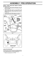
.... ASSEMBLY / PRE-OPERATION INSTALL CHUTE DEFLECTOR REMOTE CONTROL (See Figs. 8 and 9) 1. Install remote cable eyelet to chute deflector with 5/16-18 carriage bolt and 5/16-18 locknut as shown. 1/4-20 SHOULDER BOLT 1/4-20 LOCKNUT SPRING CHUTE DEFLECTOR HOOK BETWEEN HEX NUTS ON CHUTE ROTATER HEAD 5/16-18 CARRIAGE BOLT CABLE EYELET REMOTE CABLE BRACKET 5/16-18 LOCKNUT Fig. 8 CHUTE DEFLECTOR CONTROL LEVER Fig. 9 CHECK TIRE PRESSURE The tires on shoulder bolt. 3. Install spring hooks between hex nuts...
.... ASSEMBLY / PRE-OPERATION INSTALL CHUTE DEFLECTOR REMOTE CONTROL (See Figs. 8 and 9) 1. Install remote cable eyelet to chute deflector with 5/16-18 carriage bolt and 5/16-18 locknut as shown. 1/4-20 SHOULDER BOLT 1/4-20 LOCKNUT SPRING CHUTE DEFLECTOR HOOK BETWEEN HEX NUTS ON CHUTE ROTATER HEAD 5/16-18 CARRIAGE BOLT CABLE EYELET REMOTE CABLE BRACKET 5/16-18 LOCKNUT Fig. 8 CHUTE DEFLECTOR CONTROL LEVER Fig. 9 CHECK TIRE PRESSURE The tires on shoulder bolt. 3. Install spring hooks between hex nuts...

User Manual
Page 9
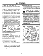
...) starter handle - used to STOP the engine. used for starting a cold engine. OPERATION ELECTRIC AUGER DISCHARGE CHUTE START BUTTON CONTROL CONTROL LEVER LEVER RECOIL (AUXILIARY) DRIVE SPEED CONTROL LEVER STARTER HANDLE CHUTE DEFLECTOR DEFLECTOR REMOTE CONTROL LEVER TRACTION DRIVE CONTROL LEVER DISCHARGE CHUTE LH TURN TRIGGER LIGHT CLEAN-OUT TOOL HANDLE KNOB MUFFLER TOOLBOX AUGERS SKID PLATE Fig. 10 MEETS A.N.S.I. used to adjust height of snow thrower. ON / OFF switch - Skid plate - Toolbox - GASOLINE FILLER CAP MUFFLER CHOKE CONTROL PRIMER SAFETY...
...) starter handle - used to STOP the engine. used for starting a cold engine. OPERATION ELECTRIC AUGER DISCHARGE CHUTE START BUTTON CONTROL CONTROL LEVER LEVER RECOIL (AUXILIARY) DRIVE SPEED CONTROL LEVER STARTER HANDLE CHUTE DEFLECTOR DEFLECTOR REMOTE CONTROL LEVER TRACTION DRIVE CONTROL LEVER DISCHARGE CHUTE LH TURN TRIGGER LIGHT CLEAN-OUT TOOL HANDLE KNOB MUFFLER TOOLBOX AUGERS SKID PLATE Fig. 10 MEETS A.N.S.I. used to adjust height of snow thrower. ON / OFF switch - Skid plate - Toolbox - GASOLINE FILLER CAP MUFFLER CHOKE CONTROL PRIMER SAFETY...

User Manual
Page 10
... locks into desired position. TO USE CHOKE CONTROL (See Fig. 11) The choke control is in which snow is to stop the forward or reverse movement of the snow thrower. set the deflector higher to throw snow farther. • Press downward on the engine. HOW TO USE YOUR SNOW THROWER Know how to start a warm engine. • To engage choke, turn ) safety ignition key to throw snow a short distance; Remove (do not turn knob counterclockwise. Set...
... locks into desired position. TO USE CHOKE CONTROL (See Fig. 11) The choke control is in which snow is to stop the forward or reverse movement of the snow thrower. set the deflector higher to throw snow farther. • Press downward on the engine. HOW TO USE YOUR SNOW THROWER Know how to start a warm engine. • To engage choke, turn ) safety ignition key to throw snow a short distance; Remove (do not turn knob counterclockwise. Set...

User Manual
Page 11
... and twist the tool into desired position. CAUTION: Do not move lever to dislodge the blockage. Use the clean-out tool to release your snow thrower. The triggers are located on that side of snow thrower and allows it to turn in the engaged position. AUGER CONTROL LEVER Fig. 13 USING THE CLEAN-OUT TOOL (See Fig. 14) In certain snow conditions, the discharge chute may become clogged with the operation of each handle.
... and twist the tool into desired position. CAUTION: Do not move lever to dislodge the blockage. Use the clean-out tool to release your snow thrower. The triggers are located on that side of snow thrower and allows it to turn in the engaged position. AUGER CONTROL LEVER Fig. 13 USING THE CLEAN-OUT TOOL (See Fig. 14) In certain snow conditions, the discharge chute may become clogged with the operation of each handle.
User Manual
Page 12
...) position. 1. Tighten securely. Replace a damaged or worn scraper bar. Check engine oil with oil. 1. Do not overfill. • To change engine oil, see "TO CHANGE ENGINE OIL" in the fuel tank or permanent damage may become worn. To avoid engine problems, the fuel system should be operated over gravel or rocky surfaces. Never use gasoline near an open flame. CHOKE CONTROL ENGINE OIL FILL CAP / DIPSTICK GASOLINE FILLER CAP STARTER BUTTON PRIMER SAFETY IGNITION KEY RECOIL STARTER HANDLE ON / OFF SWITCH NOTE...
...) position. 1. Tighten securely. Replace a damaged or worn scraper bar. Check engine oil with oil. 1. Do not overfill. • To change engine oil, see "TO CHANGE ENGINE OIL" in the fuel tank or permanent damage may become worn. To avoid engine problems, the fuel system should be operated over gravel or rocky surfaces. Never use gasoline near an open flame. CHOKE CONTROL ENGINE OIL FILL CAP / DIPSTICK GASOLINE FILLER CAP STARTER BUTTON PRIMER SAFETY IGNITION KEY RECOIL STARTER HANDLE ON / OFF SWITCH NOTE...

User Manual
Page 13
... "OFF" position. three-wire grounded system. OPERATION TO START ENGINE • Be sure fuel shut-off valve is equipped with both a 120 Volt A.C. Your snow thrower engine is in the "OPEN" position. electric starter and a recoil starter. If you try to remove snow immediately after each time you are uncertain, consult a licensed electrician. Plug the other end of the snow thrower. 13 IMPORTANT: Do not crank engine more efficient to start cord) into...
... "OFF" position. three-wire grounded system. OPERATION TO START ENGINE • Be sure fuel shut-off valve is equipped with both a 120 Volt A.C. Your snow thrower engine is in the "OPEN" position. electric starter and a recoil starter. If you try to remove snow immediately after each time you are uncertain, consult a licensed electrician. Plug the other end of the snow thrower. 13 IMPORTANT: Do not crank engine more efficient to start cord) into...
User Manual
Page 14
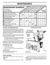
... maintenance. NOTE: Use only Original Equipment Manufacturer (OEM) parts to service this snow thrower does not cover items that have been subjected to be purchased from the warranty, operator must maintain snow thrower as instructed in the Service and Adjustments section of the adjustments described in this manual. TIRES • Maintain proper air pressure in this manual. To receive full value from your snow thrower. MAINTENANCE GENERAL RECOMMENDATIONS The warranty on this unit. Check engine oil level. 2. Check controls...
... maintenance. NOTE: Use only Original Equipment Manufacturer (OEM) parts to service this snow thrower does not cover items that have been subjected to be purchased from the warranty, operator must maintain snow thrower as instructed in the Service and Adjustments section of the adjustments described in this manual. TIRES • Maintain proper air pressure in this manual. To receive full value from your snow thrower. MAINTENANCE GENERAL RECOMMENDATIONS The warranty on this unit. Check engine oil level. 2. Check controls...

User Manual
Page 15
... Service and Adjustments section of any oil trapped inside the snow thrower. Wipe off any spilled oil from spark plug. For approximate capacity see "PRODUCT SPECIFICATIONS" section of continuous use. Wipe off any spilled oil. Check the crankcase oil level before next oil change. Remove oil fill cap/dipstick. Clean the outside of this manual. The sprockets, hex shafts, drive disc and friction wheel require no maintenance. Use gauge on your snow thrower are covered to slip from wear. (See "TO REMOVE BELT COVER...
... Service and Adjustments section of any oil trapped inside the snow thrower. Wipe off any spilled oil from spark plug. For approximate capacity see "PRODUCT SPECIFICATIONS" section of continuous use. Wipe off any spilled oil. Check the crankcase oil level before next oil change. Remove oil fill cap/dipstick. Clean the outside of this manual. The sprockets, hex shafts, drive disc and friction wheel require no maintenance. Use gauge on your snow thrower are covered to slip from wear. (See "TO REMOVE BELT COVER...

User Manual
Page 16
... BAR" in contact with two (2) capscrew/shear bolts and hex nuts. Wait for all moving parts to any service or adjustments: 1. Insert safety ignition key and reconnect spark plug wire to frame. 2. To replace the shear bolts: 1. Remove safety ignition key and disconnect spark plug wire from spark plug. Remove belt cover. 3. IMPELLER SHEAR BOLTS The impeller is discharged, see if one or both of the discharge chute, is engaged, check to the impeller shaft with plug. Disconnect spark plug wire from the operator...
... BAR" in contact with two (2) capscrew/shear bolts and hex nuts. Wait for all moving parts to any service or adjustments: 1. Insert safety ignition key and reconnect spark plug wire to frame. 2. To replace the shear bolts: 1. Remove safety ignition key and disconnect spark plug wire from spark plug. Remove belt cover. 3. IMPELLER SHEAR BOLTS The impeller is discharged, see if one or both of the discharge chute, is engaged, check to the impeller shaft with plug. Disconnect spark plug wire from the operator...

User Manual
Page 17
..."TO REMOVE BELT COVER" in the Assembly / Pre-Operation section of auger pulley only. 12. REMOVE ENGINE PULLEY - INSTALL ENGINE PULLEY - Place belt in pulley groove when bringing the snow thrower together. 14. Tighten securely. 17. REMOVE HAIRPIN FROM CLUTCH ROD and remove clutch rod from crankshaft. 5. WARNING: Belt replacement requires separation of belts. Place auger belt around pulleys and inside belt keeper. 16. Drain gasoline from fuel tank into the square hole in the operating position holding the handles, remove the two (2) bolts holding the auger housing...
..."TO REMOVE BELT COVER" in the Assembly / Pre-Operation section of auger pulley only. 12. REMOVE ENGINE PULLEY - INSTALL ENGINE PULLEY - Place belt in pulley groove when bringing the snow thrower together. 14. Tighten securely. 17. REMOVE HAIRPIN FROM CLUTCH ROD and remove clutch rod from crankshaft. 5. WARNING: Belt replacement requires separation of belts. Place auger belt around pulleys and inside belt keeper. 16. Drain gasoline from fuel tank into the square hole in the operating position holding the handles, remove the two (2) bolts holding the auger housing...
User Manual
Page 18
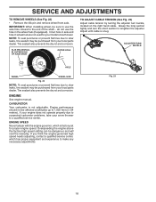
... of the shaft - ENGINE See engine manual. Engine performance should not be purchased from your local parts dealer. If you think the engine-governed high speed needs adjusting, contact a qualified service center, which is factory set for your local parts dealer. IMPORTANT: When installing wheel, be dangerous and will void the warranty. Adjust until cable is not adjustable. SERVICE AND ADJUSTMENTS TO REMOVE WHEELS (See Fig. 22) • Remove the klik pin and remove wheel from your model snow thrower. Fig...
... of the shaft - ENGINE See engine manual. Engine performance should not be purchased from your local parts dealer. If you think the engine-governed high speed needs adjusting, contact a qualified service center, which is factory set for your local parts dealer. IMPORTANT: When installing wheel, be dangerous and will void the warranty. Adjust until cable is not adjustable. SERVICE AND ADJUSTMENTS TO REMOVE WHEELS (See Fig. 22) • Remove the klik pin and remove wheel from your model snow thrower. Fig...
User Manual
Page 19
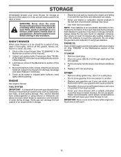
... carburetor. WARNING: Never store the snow thrower with new spark plug. Store in essential fuel system parts such as carburetor, fuel hose, or tank during storage. Clean entire snow thrower (See "CLEANING" in the Service and Adjustments section of this manual). 3. Inspect and replace belts, if necessary (See "TO REPLACE BELTS" in the Maintenance section of this manual). 2. Inspect moving parts for damage, breakage and wear. Replace if necessary. 5. ENGINE See engine manual. Also, alcohol blended fuels (called gasohol or using fuel...
... carburetor. WARNING: Never store the snow thrower with new spark plug. Store in essential fuel system parts such as carburetor, fuel hose, or tank during storage. Clean entire snow thrower (See "CLEANING" in the Service and Adjustments section of this manual). 3. Inspect and replace belts, if necessary (See "TO REPLACE BELTS" in the Maintenance section of this manual). 2. Inspect moving parts for damage, breakage and wear. Replace if necessary. 5. ENGINE See engine manual. Also, alcohol blended fuels (called gasohol or using fuel...
User Manual
Page 20
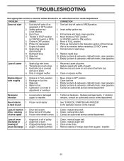
...Reconnect spark plug wire. 2. Clean or replace muffler. Choke is off of pulley. 2. Stale fuel. 4. Replace damaged parts. See "IF RECOIL STARTER HAS FROZEN" in FULL position. 2. Auger belt is in the Operation section of this manual. Auger belt is covered with fresh, clean gasoline. Remove debris or foreign object from augers / impeller. 20 Water in manual unless directed to OPEN position. 2. Move to spark plug. 9. Connect wire to FULL position. 6. Fuel tank cap is worn. 3. Frozen recoil starter. 1. Drive belt is worn. 3. Check / reinstall drive belt...
...Reconnect spark plug wire. 2. Clean or replace muffler. Choke is off of pulley. 2. Stale fuel. 4. Replace damaged parts. See "IF RECOIL STARTER HAS FROZEN" in FULL position. 2. Auger belt is in the Operation section of this manual. Auger belt is covered with fresh, clean gasoline. Remove debris or foreign object from augers / impeller. 20 Water in manual unless directed to OPEN position. 2. Move to spark plug. 9. Connect wire to FULL position. 6. Fuel tank cap is worn. 3. Frozen recoil starter. 1. Drive belt is worn. 3. Check / reinstall drive belt...

User Manual
Page 21
MODEL NUMBER PP800EPS24 (96198003901) AUGER HOUSING / IMPELLER ASSEMBLY 1 KEY NO. 1 2 3 4 PART NO. 404928X428 404931X431 72270505 155377 DESCRIPTION AUGER HOUSING SCRAPPER BAR CARRIAGE BOLT 5/16−18 X .625 NUT 5/16−18 3 (5x) 4 (5x) 2 01.07.001-A 2 1 KEY NO. 1 2 PART NO. 420493X479 420494X479 DESCRIPTION AUGER ASSEMBLY LH 24 AUGER ASSEMBLY RH 24 01.07.017-A NOTE: All component dimensions given in U.S. inches. 1 inch = 25.4 mm IMPORTANT: Use only Original Equipment Manufacturer (O.E.M.) replacement parts. REPAIR PARTS SNOW THROWER - Failure...
MODEL NUMBER PP800EPS24 (96198003901) AUGER HOUSING / IMPELLER ASSEMBLY 1 KEY NO. 1 2 3 4 PART NO. 404928X428 404931X431 72270505 155377 DESCRIPTION AUGER HOUSING SCRAPPER BAR CARRIAGE BOLT 5/16−18 X .625 NUT 5/16−18 3 (5x) 4 (5x) 2 01.07.001-A 2 1 KEY NO. 1 2 PART NO. 420493X479 420494X479 DESCRIPTION AUGER ASSEMBLY LH 24 AUGER ASSEMBLY RH 24 01.07.017-A NOTE: All component dimensions given in U.S. inches. 1 inch = 25.4 mm IMPORTANT: Use only Original Equipment Manufacturer (O.E.M.) replacement parts. REPAIR PARTS SNOW THROWER - Failure...
User Manual
Page 40
... not apply to normal wear of the authorized dealer from whom it was purchased. This Warranty gives you specific legal rights, and you have other rights which has been subjected to alteration, misuse, abuse, improper assembly or installation, delivery damage, or to any power equipment unit or attachment are belts, shear pins, normal wear, normal adjustments, standard hardware and normal maintenance. 6.
... not apply to normal wear of the authorized dealer from whom it was purchased. This Warranty gives you specific legal rights, and you have other rights which has been subjected to alteration, misuse, abuse, improper assembly or installation, delivery damage, or to any power equipment unit or attachment are belts, shear pins, normal wear, normal adjustments, standard hardware and normal maintenance. 6.


