

User Manual
Page 2
... it cannot contact plug in serious injury. Preparation 1. Do not operate the equipment without proper instruction. 3. Handle fuel with a plastic liner. Operation 1. Keep clear of amputating hands and feet and throwing objects. Never fill fuel tank indoors. 3. If the unit should be used and remove all instructions on a trailer with electric drive motors or electric starting when setting up spilled fuel. (h) If fuel is running engine or hot engine. from your vehicle...
... it cannot contact plug in serious injury. Preparation 1. Do not operate the equipment without proper instruction. 3. Handle fuel with a plastic liner. Operation 1. Keep clear of amputating hands and feet and throwing objects. Never fill fuel tank indoors. 3. If the unit should be used and remove all instructions on a trailer with electric drive motors or electric starting when setting up spilled fuel. (h) If fuel is running engine or hot engine. from your vehicle...
User Manual
Page 3
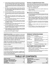
... use . 14. Never operate the snow thrower without proper guards, and other bolts at high transport speeds on slopes. 9. 6. Keep children and others away. 11. Never store the machine with snow throwers. Always refer to service or repair this manual. TABLE OF CONTENTS SAFETY RULES 2-3 MAINTENANCE 13-14 PRODUCT SPECIFICATIONS 3 SERVICE AND ADJUSTMENTS 15-17 CUSTOMER RESPONSIBILITIES 3 STORAGE 17 ASSEMBLY / PRE-OPERATION 4-7 TROUBLESHOOTING 18 OPERATION 8-12 REPAIR PARTS 20-37 MAINTENANCE SCHEDULE 13 3 WARRANTY BACK COVER...
... use . 14. Never operate the snow thrower without proper guards, and other bolts at high transport speeds on slopes. 9. 6. Keep children and others away. 11. Never store the machine with snow throwers. Always refer to service or repair this manual. TABLE OF CONTENTS SAFETY RULES 2-3 MAINTENANCE 13-14 PRODUCT SPECIFICATIONS 3 SERVICE AND ADJUSTMENTS 15-17 CUSTOMER RESPONSIBILITIES 3 STORAGE 17 ASSEMBLY / PRE-OPERATION 4-7 TROUBLESHOOTING 18 OPERATION 8-12 REPAIR PARTS 20-37 MAINTENANCE SCHEDULE 13 3 WARRANTY BACK COVER...
User Manual
Page 4
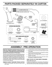
.... 4 located on your snow thrower. PARTS PACKED SEPARATELY IN CARTON (1) AUGER CONTROL ROD (1) TRACTION DRIVE CONTROL ROD (1) DISCHARGE CHUTE (1) POWER CORD (198563) ROTATOR HEAD MOUNTING (1) MULTIWRENCH (180684) (3) RETAINER SPRINGS (169675) (2) FLAT WASHERS (2) CARRIAGE BOLTS 3/8-16 x 2.25 (1) WASHER 3/8 (19131316) (1) LOCKNUT 3/8 (73800600) EXTRA SHEAR BOLTS AND NUTS (1) SAFTEY IGNITION KEY (35062) (2) HANDLE KNOBS (2) SHEAR BOLTS 1/4-20 x 1-3/4 (198636) (2) SPACERS (198638) (2) LOCKNUTS 1/4-20 (73800400) ASSEMBLY / PRE-OPERATION Read these instructions and this manual in...
.... 4 located on your snow thrower. PARTS PACKED SEPARATELY IN CARTON (1) AUGER CONTROL ROD (1) TRACTION DRIVE CONTROL ROD (1) DISCHARGE CHUTE (1) POWER CORD (198563) ROTATOR HEAD MOUNTING (1) MULTIWRENCH (180684) (3) RETAINER SPRINGS (169675) (2) FLAT WASHERS (2) CARRIAGE BOLTS 3/8-16 x 2.25 (1) WASHER 3/8 (19131316) (1) LOCKNUT 3/8 (73800600) EXTRA SHEAR BOLTS AND NUTS (1) SAFTEY IGNITION KEY (35062) (2) HANDLE KNOBS (2) SHEAR BOLTS 1/4-20 x 1-3/4 (198636) (2) SPACERS (198638) (2) LOCKNUTS 1/4-20 (73800400) ASSEMBLY / PRE-OPERATION Read these instructions and this manual in...

User Manual
Page 5
... end of rod positioned under left side of control panel, push rod down and insert top end of rod into pivot bracket with loop opening down as shown. 1. ASSEMBLY / PRE-OPERATION NOTE: The multi-wrench may be used for assembly of the chute rotator head to snow thrower and making adjustments to the operating position and tighten handle knobs securely. UNFOLD UPPER HANDLE 1. INSTALL SPEED CONTROL ROD (See Figs...
... end of rod positioned under left side of control panel, push rod down and insert top end of rod into pivot bracket with loop opening down as shown. 1. ASSEMBLY / PRE-OPERATION NOTE: The multi-wrench may be used for assembly of the chute rotator head to snow thrower and making adjustments to the operating position and tighten handle knobs securely. UNFOLD UPPER HANDLE 1. INSTALL SPEED CONTROL ROD (See Figs...

User Manual
Page 6
.... 4. Position chute rotater head over chute bracket. If necessary, rotate chute assembly to 14-17 PSI (19-24.5 N-m). CHUTE ROTATER HEAD 3/8 LOCKNUT 3/8 WASHER LOOP OPENING UP FIG. 5 AUGER CONTROL ROD AUGER CONTROL RETAINER LEVER SPRING PIN THREADED STUD CHUTE BRACKET ALIGN BEFORE TIGHTENING LOCKNUT FIG. 7 ROTATER HEAD MOUNTING BRACKET CHECK TIRE PRESSURE The tires on your parts bag may be used to install the chute rotater head. 1. ASSEMBLY / PRE-OPERATION INSTALL AUGER CONTROL ROD (See Figs. 5 and 6) The auger control rod...
.... 4. Position chute rotater head over chute bracket. If necessary, rotate chute assembly to 14-17 PSI (19-24.5 N-m). CHUTE ROTATER HEAD 3/8 LOCKNUT 3/8 WASHER LOOP OPENING UP FIG. 5 AUGER CONTROL ROD AUGER CONTROL RETAINER LEVER SPRING PIN THREADED STUD CHUTE BRACKET ALIGN BEFORE TIGHTENING LOCKNUT FIG. 7 ROTATER HEAD MOUNTING BRACKET CHECK TIRE PRESSURE The tires on your parts bag may be used to install the chute rotater head. 1. ASSEMBLY / PRE-OPERATION INSTALL AUGER CONTROL ROD (See Figs. 5 and 6) The auger control rod...

User Manual
Page 8
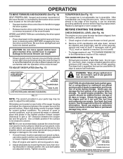
...used to engage auger motion (throw snow). ACTUAL LOCATION MAY VARY WITH THE ENGINE ON YOUR UNIT. Toolbox - Primer - Drive speed control lever - OPERATION SAFETY IGNITION KEY SPARK PLUG CHOKE CONTROL ENGINE OIL CAP WITH DIPSTICK AUGER CONTROL LEVER GASOLINE FILLER CAP DISCHARGE CHUTE CONTROL LEVER DRIVE SPEED CONTROL LEVER TRACTION DRIVE CONTROL LEVER CHUTE DEFLECTOR FUEL SHUT-OFF VALVE THROTTLE / ENGINE CONTROL DISCHARGE CHUTE RECOIL STARTER HANDLE POWER CORD PLUG ELECTRIC START BUTTON PRIMER OIL DRAIN PLUG CLEAN-OUT TOOL LIGHT CHUTE DEFLECTOR KNOB HANDLE...
...used to engage auger motion (throw snow). ACTUAL LOCATION MAY VARY WITH THE ENGINE ON YOUR UNIT. Toolbox - Primer - Drive speed control lever - OPERATION SAFETY IGNITION KEY SPARK PLUG CHOKE CONTROL ENGINE OIL CAP WITH DIPSTICK AUGER CONTROL LEVER GASOLINE FILLER CAP DISCHARGE CHUTE CONTROL LEVER DRIVE SPEED CONTROL LEVER TRACTION DRIVE CONTROL LEVER CHUTE DEFLECTOR FUEL SHUT-OFF VALVE THROTTLE / ENGINE CONTROL DISCHARGE CHUTE RECOIL STARTER HANDLE POWER CORD PLUG ELECTRIC START BUTTON PRIMER OIL DRAIN PLUG CLEAN-OUT TOOL LIGHT CHUTE DEFLECTOR KNOB HANDLE...

User Manual
Page 9
HOW TO USE YOUR SNOW THROWER Know how to operate all times including startup. STOPPING TRACTION DRIVE • Release traction drive control lever to start a warm engine. • To engage choke, turn knob counterclockwise to stop the forward or reverse movement of the snow thrower. Move throttle control to prevent unauthorized use. Remove (do not turn) safety ignition key to "STOP" position. 2. Be sure lever springs back and locks into the eyes, which can cause severe injury...
HOW TO USE YOUR SNOW THROWER Know how to operate all times including startup. STOPPING TRACTION DRIVE • Release traction drive control lever to start a warm engine. • To engage choke, turn knob counterclockwise to stop the forward or reverse movement of the snow thrower. Move throttle control to prevent unauthorized use. Remove (do not turn) safety ignition key to "STOP" position. 2. Be sure lever springs back and locks into the eyes, which can cause severe injury...

User Manual
Page 10
... drive control lever located on the speed control lever and move speed control lever when traction drive control lever is recommended that you use a slower speed until you to release your right hand from the handle and adjust the discharge chute direction without interrupting the snow throwing process. • Release the auger control lever and shut off the engine. • Remove the clean-out tool from the spark plug to stop throwing snow. OPERATION HIGH POSITION • Restart the engine, then squeeze the auger control lever...
... drive control lever located on the speed control lever and move speed control lever when traction drive control lever is recommended that you use a slower speed until you to release your right hand from the handle and adjust the discharge chute direction without interrupting the snow throwing process. • Release the auger control lever and shut off the engine. • Remove the clean-out tool from the spark plug to stop throwing snow. OPERATION HIGH POSITION • Restart the engine, then squeeze the auger control lever...
User Manual
Page 11
.... CHOKE CONTROL THROTTLE PRIMER ENGINE OIL FILL CAP / DIPSTICK SAFETY IGNITION KEY GASOLINE FILLER CAP RECOIL STARTER HANDLE FUEL SHUTOFF VALVE STARTER BUTTON POWER CORD PLUG NOTE: ALL ITEMS ARE SHOWN IN THEIR TYPICAL LOCATION. ADD GASOLINE (See Fig. 18) • Fill fuel tank to be sure skid plates are adjusted to lowest (highest scraper clearance) position. 1. Do not mix oil with oil. 1. Acidic gas can attract moisture which can be emptied before requiring replacement. ACTUAL LOCATION MAY...
.... CHOKE CONTROL THROTTLE PRIMER ENGINE OIL FILL CAP / DIPSTICK SAFETY IGNITION KEY GASOLINE FILLER CAP RECOIL STARTER HANDLE FUEL SHUTOFF VALVE STARTER BUTTON POWER CORD PLUG NOTE: ALL ITEMS ARE SHOWN IN THEIR TYPICAL LOCATION. ADD GASOLINE (See Fig. 18) • Fill fuel tank to be sure skid plates are adjusted to lowest (highest scraper clearance) position. 1. Do not mix oil with oil. 1. Acidic gas can attract moisture which can be emptied before requiring replacement. ACTUAL LOCATION MAY...

User Manual
Page 12
... engine clean and clear of the starter as follows: 1. household current. Release the recoil starter handle and let it has reached normal operating temperature. ELECTRIC STARTER 1. Allow the engine to "FULL" position. 4. Engine will not develop full power until engine starts. Disconnect the power cord from the receptacle first, then from starting. three-wire grounded system. See "TO ADJUST SKID PLATES" in deep, freezing or heavy wet snow. Your snow thrower engine is...
... engine clean and clear of the starter as follows: 1. household current. Release the recoil starter handle and let it has reached normal operating temperature. ELECTRIC STARTER 1. Allow the engine to "FULL" position. 4. Engine will not develop full power until engine starts. Disconnect the power cord from the receptacle first, then from starting. three-wire grounded system. See "TO ADJUST SKID PLATES" in deep, freezing or heavy wet snow. Your snow thrower engine is...
User Manual
Page 13
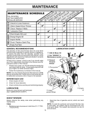
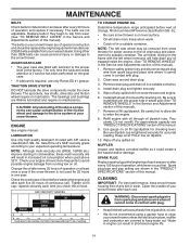
... should replace the spark plug and check belts for loose fasteners. 3. At least once a season, check to slow leaks, tire sealant may be sure they are functioning properly. Check for wear. Check engine oil level. 2. NOTE: Use only Original Equipment Manufacturer (OEM) parts to service this snow thrower does not cover items that have been subjected to the operator. Check controls to be purchased from the warranty, operator must maintain snow thrower as instructed in Maintenance...
... should replace the spark plug and check belts for loose fasteners. 3. At least once a season, check to slow leaks, tire sealant may be sure they are functioning properly. Check for wear. Check engine oil level. 2. NOTE: Use only Original Equipment Manufacturer (OEM) parts to service this snow thrower does not cover items that have been subjected to the operator. Check controls to be purchased from the warranty, operator must maintain snow thrower as instructed in Maintenance...
User Manual
Page 14
... anticipated before starting in the Service and Adjustments section of this manual). 1. NOTE: The left side wheel may be replaced by original equipment manufacturer (OEM) belts available from snow thrower and engine. 6. Wipe off any spilled oil from your snow thrower. Use gauge on your snow thrower unless the electrical system, muffler and carburetor are covered to the snow thrower. CLEANING IMPORTANT: For best performance, keep water out. WARNING: Disconnect spark plug wire from snow thrower for checking level. Water in...
... anticipated before starting in the Service and Adjustments section of this manual). 1. NOTE: The left side wheel may be replaced by original equipment manufacturer (OEM) belts available from snow thrower and engine. 6. Wipe off any spilled oil from your snow thrower. Use gauge on your snow thrower unless the electrical system, muffler and carburetor are covered to the snow thrower. CLEANING IMPORTANT: For best performance, keep water out. WARNING: Disconnect spark plug wire from snow thrower for checking level. Water in...
User Manual
Page 15
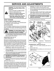
... with plug. 3. SNOW THROWER TO ADJUST SNOW THROWER HEIGHT See "TO ADJUST SKID PLATES" and "SCRAPER BAR" in the impeller, the capscrews are secured to STOP position. BELT COVER CAUTION: Do not substitute. WARNING: To avoid serious injury, never operate your snow thrower. Wait for all controls and move throttle control to the impeller shaft with holes in auger shaft and install a new 1/4-20 x 2" shoulder/shear bolt and spacer. Remove the two (2) screws securing belt cover to spark plug. Use only...
... with plug. 3. SNOW THROWER TO ADJUST SNOW THROWER HEIGHT See "TO ADJUST SKID PLATES" and "SCRAPER BAR" in the impeller, the capscrews are secured to STOP position. BELT COVER CAUTION: Do not substitute. WARNING: To avoid serious injury, never operate your snow thrower. Wait for all controls and move throttle control to the impeller shaft with holes in auger shaft and install a new 1/4-20 x 2" shoulder/shear bolt and spacer. Remove the two (2) screws securing belt cover to spark plug. Use only...

User Manual
Page 16
... while bringing snow thrower together), separate the snow thrower and repeat step 12. Drain gasoline from fuel tank into the square hole in the operating position holding the handles, remove the two (2) bolts holding the auger housing and frame together. REMOVE BELT COVER - REMOVE ENGINE PULLEY - Serious personal injury and/ or damage to rejoin the auger housing and frame assembly, pull up any spilled gasoline. 2. INSTALL ENGINE PULLEY - See "INSTALL DISCHARGE CHUTE / CHUTE ROTATER HEAD" in this section of belts. Using other than...
... while bringing snow thrower together), separate the snow thrower and repeat step 12. Drain gasoline from fuel tank into the square hole in the operating position holding the handles, remove the two (2) bolts holding the auger housing and frame together. REMOVE BELT COVER - REMOVE ENGINE PULLEY - Serious personal injury and/ or damage to rejoin the auger housing and frame assembly, pull up any spilled gasoline. 2. INSTALL ENGINE PULLEY - See "INSTALL DISCHARGE CHUTE / CHUTE ROTATER HEAD" in this section of belts. Using other than...
User Manual
Page 17
... snow thrower (See "CLEANING" in the Service and Adjustments section of this manual). Add stabilizer to distribute oil. 4. Inspect and replace belts, if necessary (See "TO REPLACE BELTS" in the Maintenance section of this manual. 4. Lubricate as shown in fuel tank or storage container. Pull recoil starter handle slowly a few times to gasoline in the Maintenance section of this manual). • Empty the fuel tank by starting the engine and letting it run until the fuel lines and carburetor...
... snow thrower (See "CLEANING" in the Service and Adjustments section of this manual). Add stabilizer to distribute oil. 4. Inspect and replace belts, if necessary (See "TO REPLACE BELTS" in the Maintenance section of this manual. 4. Lubricate as shown in fuel tank or storage container. Pull recoil starter handle slowly a few times to gasoline in the Maintenance section of this manual). • Empty the fuel tank by starting the engine and letting it run until the fuel lines and carburetor...

User Manual
Page 18
... of power 1. Primer not depressed. 7. Insert safety ignition key. 3. Loss of fuel. 4. Throwing too much snow. 3. Reconnect spark plug wire. 2. Water in STOP position 5. Frozen recoil starter. 1. Drive belt is covered with fresh, clean gasoline. Friction drive wheel is flooded. 8. Check / replace auger belt. 3. Throttle in fuel. 5. Engine is worn. 3. Spark plug wire is in FULL position. 2. Bad spark plug. 10. Wait a few minutes before restarting, DO NOT prime. 8. Fuel tank cap is off valve (if so equipped) in OFF position. 2. Dirty or clogged muffler...
... of power 1. Primer not depressed. 7. Insert safety ignition key. 3. Loss of fuel. 4. Throwing too much snow. 3. Reconnect spark plug wire. 2. Water in STOP position 5. Frozen recoil starter. 1. Drive belt is covered with fresh, clean gasoline. Friction drive wheel is flooded. 8. Check / replace auger belt. 3. Throttle in fuel. 5. Engine is worn. 3. Spark plug wire is in FULL position. 2. Bad spark plug. 10. Wait a few minutes before restarting, DO NOT prime. 8. Fuel tank cap is off valve (if so equipped) in OFF position. 2. Dirty or clogged muffler...

User Manual
Page 21
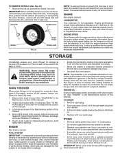
... WORM GEAR AUGER SHAFT SQUARE KEY BEARING THRUST WASHER IMPELLER SHAFT ROLL PIN THRUST WASHER THRUST BEARING BEARING O−RING SCREW 5/16−18 X .750 GEARBOX COVER LH NOTE: All component dimensions given in U.S. Failure to do so could be hazardous, damage your snow thrower and void your warranty. 21 inches. 1 inch = 25.4 mm IMPORTANT: Use only Original Equipment Manufacturer (O.E.M.) replacement parts. REPAIR PARTS SNOW THROWER - - MODEL NUMBER PR5524ES (96192001607) AUGER HOUSING / IMPELLER ASSEMBLY KEY...
... WORM GEAR AUGER SHAFT SQUARE KEY BEARING THRUST WASHER IMPELLER SHAFT ROLL PIN THRUST WASHER THRUST BEARING BEARING O−RING SCREW 5/16−18 X .750 GEARBOX COVER LH NOTE: All component dimensions given in U.S. Failure to do so could be hazardous, damage your snow thrower and void your warranty. 21 inches. 1 inch = 25.4 mm IMPORTANT: Use only Original Equipment Manufacturer (O.E.M.) replacement parts. REPAIR PARTS SNOW THROWER - - MODEL NUMBER PR5524ES (96192001607) AUGER HOUSING / IMPELLER ASSEMBLY KEY...
User Manual
Page 22
... DESCRIPTION AUGER HOUSING SCRAPPER BAR CARRIAGE BOLT 5/16−18 X .625 NUT 5/16−18 3 (5x) 4 (5x) 2 01.07.001-A 2 1 KEY NO. 1 2 PART NO. 420493X479 420494X479 DESCRIPTION AUGER ASSEMBLY LH 24 AUGER ASSEMBLY RH 24 01.07.017-A NOTE: All component dimensions given in U.S. Failure to do so could be hazardous, damage your snow thrower and void your warranty. 22 inches. 1 inch = 25.4 mm IMPORTANT: Use...
... DESCRIPTION AUGER HOUSING SCRAPPER BAR CARRIAGE BOLT 5/16−18 X .625 NUT 5/16−18 3 (5x) 4 (5x) 2 01.07.001-A 2 1 KEY NO. 1 2 PART NO. 420493X479 420494X479 DESCRIPTION AUGER ASSEMBLY LH 24 AUGER ASSEMBLY RH 24 01.07.017-A NOTE: All component dimensions given in U.S. Failure to do so could be hazardous, damage your snow thrower and void your warranty. 22 inches. 1 inch = 25.4 mm IMPORTANT: Use...
User Manual
Page 37
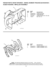
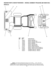
... 187898 181033 415475 415391 415390 424053 424054 DESCRIPTION DECAL, DANGER DECAL, POULAN PRO DECAL, DANGER, DEFLECTOR DECAL, DANGER DECAL, POULAN PRO DECAL, INSTRUCTION DECAL, SPEED CONTROL DECAL, TRACT/CLUTCH LEVER LH DECAL, TRACT/CLUTCH LEVER RH OWNER'S MANUAL, ENGLISH OWNER'S MANUAL, FRENCH NOTE: All component dimensions given in U.S. inches. 1 inch = 25.4 mm IMPORTANT: Use only Original Equipment Manufacturer (O.E.M.) replacement parts. MODEL NUMBER PR5524ES (96192001607) DECALS 1 2 4 12 9 6 1 3 5 11 KEY NO. 1 2 3 4 5 6 9 11 12 - - - REPAIR PARTS SNOW THROWER - -
... 187898 181033 415475 415391 415390 424053 424054 DESCRIPTION DECAL, DANGER DECAL, POULAN PRO DECAL, DANGER, DEFLECTOR DECAL, DANGER DECAL, POULAN PRO DECAL, INSTRUCTION DECAL, SPEED CONTROL DECAL, TRACT/CLUTCH LEVER LH DECAL, TRACT/CLUTCH LEVER RH OWNER'S MANUAL, ENGLISH OWNER'S MANUAL, FRENCH NOTE: All component dimensions given in U.S. inches. 1 inch = 25.4 mm IMPORTANT: Use only Original Equipment Manufacturer (O.E.M.) replacement parts. MODEL NUMBER PR5524ES (96192001607) DECALS 1 2 4 12 9 6 1 3 5 11 KEY NO. 1 2 3 4 5 6 9 11 12 - - - REPAIR PARTS SNOW THROWER - -

User Manual
Page 40
..., misuse, abuse, improper assembly or installation, delivery damage, or to materials or workmanship. ID#, serial number and date of purchase of your product and the name and address of 1975. For a period of two (2) years from defects in replacing parts, any power equipment unit or attachment are belts, shear pins, normal wear, normal adjustments, standard hardware and normal maintenance. 6. This warranty does not apply...
..., misuse, abuse, improper assembly or installation, delivery damage, or to materials or workmanship. ID#, serial number and date of purchase of your product and the name and address of 1975. For a period of two (2) years from defects in replacing parts, any power equipment unit or attachment are belts, shear pins, normal wear, normal adjustments, standard hardware and normal maintenance. 6. This warranty does not apply...


