
User Manual
Page 2
... 1. ing gravel drives, walks, or roads. Always place restarting and operating the snow thrower. containers on sidewalks, driveways and other engine parts become extremely hot during operation or while performing an adjustment or repair to point out important safety precautions. If the unit should be used and... that may be thrown from the discharge chute. Handle fuel with extreme care. Do not put hands or feet near or under rotating parts. IMPORTANT Safe Operation Practices for Walk-Behind Snow Throwers This snow thrower is to stop the unit and disengage the controls quickly. 2. ...
... 1. ing gravel drives, walks, or roads. Always place restarting and operating the snow thrower. containers on sidewalks, driveways and other engine parts become extremely hot during operation or while performing an adjustment or repair to point out important safety precautions. If the unit should be used and... that may be thrown from the discharge chute. Handle fuel with extreme care. Do not put hands or feet near or under rotating parts. IMPORTANT Safe Operation Practices for Walk-Behind Snow Throwers This snow thrower is to stop the unit and disengage the controls quickly. 2. ...
User Manual
Page 3
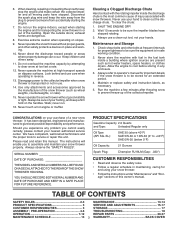
...14 PRODUCT SPECIFICATIONS 3 SERVICE AND ADJUSTMENTS 15-17 CUSTOMER RESPONSIBILITIES 3 STORAGE 17 ASSEMBLY / PRE-OPERATION 4-6 TROUBLESHOOTING 18 OPERATION 7-12 REPAIR PARTS 20-37 MAINTENANCE SCHEDULE 13 3 WARRANTY BACK COVER exhaust fumes are present such as hot water heaters, space heaters, or clothes dryers.... When cleaning, repairing or inspecting the snow thrower, stop the engine and make certain the collector/impeller and all moving parts have competent, well-trained technicians and the proper tools to clean out the discharge chute. Do not overload the machine ...
...14 PRODUCT SPECIFICATIONS 3 SERVICE AND ADJUSTMENTS 15-17 CUSTOMER RESPONSIBILITIES 3 STORAGE 17 ASSEMBLY / PRE-OPERATION 4-6 TROUBLESHOOTING 18 OPERATION 7-12 REPAIR PARTS 20-37 MAINTENANCE SCHEDULE 13 3 WARRANTY BACK COVER exhaust fumes are present such as hot water heaters, space heaters, or clothes dryers.... When cleaning, repairing or inspecting the snow thrower, stop the engine and make certain the collector/impeller and all moving parts have competent, well-trained technicians and the proper tools to clean out the discharge chute. Do not overload the machine ...

User Manual
Page 4
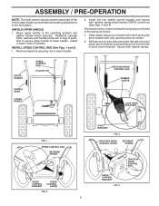
... exception of the product. To ensure safe and proper operation of your new snow thrower. Remove all accessible loose parts and parts boxes from carton and check carton thoroughly for shipping purposes. Your new snow thrower has been assembled at the factory... thrower, all four corners of the belt cover. Remove all packing materials except plastic tie holding speed control rod to ensure proper tightness. 2. PARTS PACKED SEPARATELY IN CARTON (1) AUGER CONTROL ROD (1) TRACTION DRIVE CONTROL ROD (1) DISCHARGE CHUTE (1) POWER CORD (198563) ROTATOR HEAD MOUNTING (1) MULTIWRENCH...
... exception of the product. To ensure safe and proper operation of your new snow thrower. Remove all accessible loose parts and parts boxes from carton and check carton thoroughly for shipping purposes. Your new snow thrower has been assembled at the factory... thrower, all four corners of the belt cover. Remove all packing materials except plastic tie holding speed control rod to ensure proper tightness. 2. PARTS PACKED SEPARATELY IN CARTON (1) AUGER CONTROL ROD (1) TRACTION DRIVE CONTROL ROD (1) DISCHARGE CHUTE (1) POWER CORD (198563) ROTATOR HEAD MOUNTING (1) MULTIWRENCH...
User Manual
Page 5
... retainer spring. Additional carriage bolts, washers and handle knobs are in handles. ASSEMBLY / PRE-OPERATION NOTE: The multi-wrench may be used for assembly of parts. Install in lower holes in bag of the chute rotator head to snow thrower and making adjustments to the operating position and tighten handle knobs...
... retainer spring. Additional carriage bolts, washers and handle knobs are in handles. ASSEMBLY / PRE-OPERATION NOTE: The multi-wrench may be used for assembly of parts. Install in lower holes in bag of the chute rotator head to snow thrower and making adjustments to the operating position and tighten handle knobs...

User Manual
Page 6
... snow throwing performance. • Reduce tire pressure to install the chute rotater head. 1. If necessary, rotate chute assembly to align square and pin on your parts bag may be used to 14-17 PSI (19-24.5 N-m). Correct and equal tire pressure is important for shipping purposes. Slide rubber sleeve up as...
... snow throwing performance. • Reduce tire pressure to install the chute rotater head. 1. If necessary, rotate chute assembly to align square and pin on your parts bag may be used to 14-17 PSI (19-24.5 N-m). Correct and equal tire pressure is important for shipping purposes. Slide rubber sleeve up as...

User Manual
Page 9
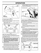
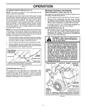
... control whenever you are starting a cold engine. OFF FULL FIG. 11 TO CONTROL SNOW DISCHARGE (See Figs. 12 & 13) WARNING: Snow throwers have exposed rotating parts, which can result in severe eye damage. Always operate the snow thrower with the fuel shut-off engine and wait for all moving... parts to be thrown is controlled by the position of the chute deflector. ENGINE 1. Do not use choke to desired position and tighten knob securely. STOPPING ...
... control whenever you are starting a cold engine. OFF FULL FIG. 11 TO CONTROL SNOW DISCHARGE (See Figs. 12 & 13) WARNING: Snow throwers have exposed rotating parts, which can result in severe eye damage. Always operate the snow thrower with the fuel shut-off engine and wait for all moving... parts to be thrown is controlled by the position of the chute deflector. ENGINE 1. Do not use choke to desired position and tighten knob securely. STOPPING ...
User Manual
Page 10
... to the snow thrower can result. • Slower speeds are for heavier snow and faster speeds are disengaged and the auger/impeller and all moving parts have stopped. When cleaning, repairing, or inspecting, make certain all controls are for light snow and transporting the snow thrower.
... to the snow thrower can result. • Slower speeds are for heavier snow and faster speeds are disengaged and the auger/impeller and all moving parts have stopped. When cleaning, repairing, or inspecting, make certain all controls are for light snow and transporting the snow thrower.
User Manual
Page 11
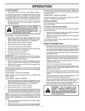
... housing, it has worn almost to stop. 2. Acidic gas can easily be picked up and thrown by loosening the hex nuts, then moving parts to the edge of the auger housing and adjust the clearance between the scraper bar and the ground. To avoid engine problems, the fuel system... the fuel lines and carburetor are adjusted to bottom of acids during storage. Use fresh, clean, regular unleaded gasoline with snow thrower on your parts bag may be reversed, providing additional service before storage of snow in normal conditions, such as gravel, rocks or other debris, can damage the...
... housing, it has worn almost to stop. 2. Acidic gas can easily be picked up and thrown by loosening the hex nuts, then moving parts to the edge of the auger housing and adjust the clearance between the scraper bar and the ground. To avoid engine problems, the fuel system... the fuel lines and carburetor are adjusted to bottom of acids during storage. Use fresh, clean, regular unleaded gasoline with snow thrower on your parts bag may be reversed, providing additional service before storage of snow in normal conditions, such as gravel, rocks or other debris, can damage the...
User Manual
Page 12
... control to help air flow and extend engine life. • After snow-throwing is ready for current snow conditions. See "TO ADJUST SKID PLATES" in parts bag) into ignition slot until engine starts. electric starter and a recoil starter. receptacle. 6. Wait 5 to the "OFF" position. 9. WARNING: Do not operate snow thrower if... A.C. RECOIL STARTER 1. OPERATION TO START ENGINE • Be sure fuel shut-off valve is equipped with both a 120 Volt A.C. Your snow thrower engine is in parts bag) into a three-hole grounded 120 Volt A.C. three-wire grounded system.
... control to help air flow and extend engine life. • After snow-throwing is ready for current snow conditions. See "TO ADJUST SKID PLATES" in parts bag) into ignition slot until engine starts. electric starter and a recoil starter. receptacle. 6. Wait 5 to the "OFF" position. 9. WARNING: Do not operate snow thrower if... A.C. RECOIL STARTER 1. OPERATION TO START ENGINE • Be sure fuel shut-off valve is equipped with both a 120 Volt A.C. Your snow thrower engine is in parts bag) into a three-hole grounded 120 Volt A.C. three-wire grounded system.

User Manual
Page 13
... and Adjustments section of injury to malfunction and pose a risk of this manual. NOTE: Use only Original Equipment Manufacturer (OEM) parts to service this snow thrower does not cover items that have been subjected to properly maintain your snow thrower well lubricated (See "LUBRICATION...sealant also prevents tire dry rot and corrosion. 13 MAINTENANCE GENERAL RECOMMENDATIONS The warranty on this unit. Some adjustments will help your local parts dealer. Check for wear. NOTE: To seal tire punctures and prevent flat tires due to slow leaks, tire sealant may be made...
... and Adjustments section of injury to malfunction and pose a risk of this manual. NOTE: Use only Original Equipment Manufacturer (OEM) parts to service this snow thrower does not cover items that have been subjected to properly maintain your snow thrower well lubricated (See "LUBRICATION...sealant also prevents tire dry rot and corrosion. 13 MAINTENANCE GENERAL RECOMMENDATIONS The warranty on this unit. Some adjustments will help your local parts dealer. Check for wear. NOTE: To seal tire punctures and prevent flat tires due to slow leaks, tire sealant may be made...
User Manual
Page 15
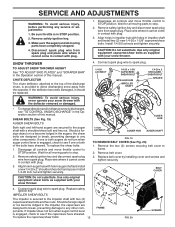
...operator. SHEAR BOLTS (See Fig. 19) AUGER SHEAR BOLTS Both right and left-hand augers are secured to stop . 2. Disengage all moving parts have completely stopped. 4. Remove safety ignition key and disconnect spark plug wire from spark plug. Install 1/4-20 lock nut and tighten securely. Disengage...object or ice become lodged in the augers, the shear bolts are designed to break, preventing damage to STOP position. Wait for all moving parts to any service or adjustments: 1. Should a foreign object or ice become lodged in the impeller, the capscrews are designed to break, ...
...operator. SHEAR BOLTS (See Fig. 19) AUGER SHEAR BOLTS Both right and left-hand augers are secured to stop . 2. Disengage all moving parts have completely stopped. 4. Remove safety ignition key and disconnect spark plug wire from spark plug. Install 1/4-20 lock nut and tighten securely. Disengage...object or ice become lodged in the augers, the shear bolts are designed to break, preventing damage to STOP position. Wait for all moving parts to any service or adjustments: 1. Should a foreign object or ice become lodged in the impeller, the capscrews are designed to break, ...
User Manual
Page 17
...minutes after adding stabilizer to allow the stabilizer to slow leaks, tire sealant may be purchased from your local parts dealer. CYLINDER 2. Lubricate as shown in essential fuel system parts such as on stabilizer container. store it in a safe place. • Do not store gasoline from ...your snow thrower to rust. Always follow the mix ratio found on a furnace, water heater, clothes dryer or gas appliance. Inspect moving parts for pushing or transporting the snow thrower), remove klik pin from dust and dirt. of fuel gum deposits during storage. ENGINE See engine ...
...minutes after adding stabilizer to allow the stabilizer to slow leaks, tire sealant may be purchased from your local parts dealer. CYLINDER 2. Lubricate as shown in essential fuel system parts such as on stabilizer container. store it in a safe place. • Do not store gasoline from ...your snow thrower to rust. Always follow the mix ratio found on a furnace, water heater, clothes dryer or gas appliance. Inspect moving parts for pushing or transporting the snow thrower), remove klik pin from dust and dirt. of fuel gum deposits during storage. ENGINE See engine ...

User Manual
Page 18
... "IF RECOIL STARTER HAS FROZEN" in manual unless directed to pull 1. of power 1. Primer not depressed. 7. Fuel tank cap is worn. 3. Loose parts or damaged augers or impeller. 1. Replace damaged parts. Auger belt is covered with fresh, clean gasoline. 5. Augers / impeller jammed. 1. Remove debris or foreign object from augers / impeller. 18 TROUBLESHOOTING...
... "IF RECOIL STARTER HAS FROZEN" in manual unless directed to pull 1. of power 1. Primer not depressed. 7. Fuel tank cap is worn. 3. Loose parts or damaged augers or impeller. 1. Replace damaged parts. Auger belt is covered with fresh, clean gasoline. 5. Augers / impeller jammed. 1. Remove debris or foreign object from augers / impeller. 18 TROUBLESHOOTING...

User Manual
Page 20
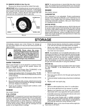
MODEL NUMBER PR5524ESNHL (96192002700) AUGER HOUSING / IMPELLER ASSEMBLY 5 11 6 15 14 13 4 12 16 11 12 3 11 1 9 10 2 11 7 8 17 33 32 34 30 31 31 29 26 28 27 35 18 25 24 23 22 21 19 01.07.004-B 36 20 21 22 23 2 (EXPLODED) NOTE: All component dimensions given in U.S. Failure to do so could be hazardous, damage your snow thrower and void your warranty. 20 inches. 1 inch = 25.4 mm IMPORTANT: Use only Original Equipment Manufacturer (O.E.M.) replacement parts. REPAIR PARTS SNOW THROWER - -
MODEL NUMBER PR5524ESNHL (96192002700) AUGER HOUSING / IMPELLER ASSEMBLY 5 11 6 15 14 13 4 12 16 11 12 3 11 1 9 10 2 11 7 8 17 33 32 34 30 31 31 29 26 28 27 35 18 25 24 23 22 21 19 01.07.004-B 36 20 21 22 23 2 (EXPLODED) NOTE: All component dimensions given in U.S. Failure to do so could be hazardous, damage your snow thrower and void your warranty. 20 inches. 1 inch = 25.4 mm IMPORTANT: Use only Original Equipment Manufacturer (O.E.M.) replacement parts. REPAIR PARTS SNOW THROWER - -

User Manual
Page 21
... SCREW 5/16−18 X .750 GEARBOX COVER LH NOTE: All component dimensions given in U.S. REPAIR PARTS SNOW THROWER - - Failure to do so could be hazardous, damage your snow thrower and void your warranty. 21 MODEL NUMBER PR5524ESNHL (96192002700) AUGER HOUSING / IMPELLER ASSEMBLY KEY NO. 1 2 3 4 5 6 7 8 9 10 11 12 13 14 15 ...16 17 18 19 20 21 22 23 24 25 26 27 28 29 30 31 32 33 34 35 36 PART NO.
... SCREW 5/16−18 X .750 GEARBOX COVER LH NOTE: All component dimensions given in U.S. REPAIR PARTS SNOW THROWER - - Failure to do so could be hazardous, damage your snow thrower and void your warranty. 21 MODEL NUMBER PR5524ESNHL (96192002700) AUGER HOUSING / IMPELLER ASSEMBLY KEY NO. 1 2 3 4 5 6 7 8 9 10 11 12 13 14 15 ...16 17 18 19 20 21 22 23 24 25 26 27 28 29 30 31 32 33 34 35 36 PART NO.

User Manual
Page 22
... to do so could be hazardous, damage your snow thrower and void your warranty. 22 REPAIR PARTS SNOW THROWER - - MODEL NUMBER PR5524ESNHL (96192002700) AUGER HOUSING / IMPELLER ASSEMBLY 1 KEY NO. 1 2 3 4 PART NO. 404928X428 404931X479 72270505 155377 DESCRIPTION AUGER HOUSING SCRAPPER BAR CARRIAGE BOLT 5/16−18 X .625 NUT 5/16−18 3 (5x) 4 (5x) 2 01...
... to do so could be hazardous, damage your snow thrower and void your warranty. 22 REPAIR PARTS SNOW THROWER - - MODEL NUMBER PR5524ESNHL (96192002700) AUGER HOUSING / IMPELLER ASSEMBLY 1 KEY NO. 1 2 3 4 PART NO. 404928X428 404931X479 72270505 155377 DESCRIPTION AUGER HOUSING SCRAPPER BAR CARRIAGE BOLT 5/16−18 X .625 NUT 5/16−18 3 (5x) 4 (5x) 2 01...

User Manual
Page 23
... PLATE RH 3 72270506 CARRIAGE BOLT 5/16−18 X .75 3 01.11.001-A 1 4 751153 NUT 5/16−18 NOTE: All component dimensions given in U.S. MODEL NUMBER PR5524ESNHL (96192002700) AUGER HOUSING / IMPELLER ASSEMBLY 2 3 1 1 2 3 01.07.024-B KEY NO. 1 2 3 PART NO. 420478 411939 179582 DESCRIPTION AUGER BEARING BEARING PLUG SCREW 5/16−18 X 1.00 3 4 2 4 KEY...
... PLATE RH 3 72270506 CARRIAGE BOLT 5/16−18 X .75 3 01.11.001-A 1 4 751153 NUT 5/16−18 NOTE: All component dimensions given in U.S. MODEL NUMBER PR5524ESNHL (96192002700) AUGER HOUSING / IMPELLER ASSEMBLY 2 3 1 1 2 3 01.07.024-B KEY NO. 1 2 3 PART NO. 420478 411939 179582 DESCRIPTION AUGER BEARING BEARING PLUG SCREW 5/16−18 X 1.00 3 4 2 4 KEY...

User Manual
Page 24
... void your warranty. 24 inches. 1 inch = 25.4 mm IMPORTANT: Use only Original Equipment Manufacturer (O.E.M.) replacement parts. REPAIR PARTS SNOW THROWER - - MODEL NUMBER PR5524ESNHL (96192002700) CONTROL PANEL / CHUTE 2 11 3 6 8 6 10 5 9 11 4 11 7 1 01.09.001-A KEY NO. 1 2 3 4 5 6 7 8 9 10 11 PART NO. 404770X428 178633X428 420325 179096X479 189713X479 128415 185600 72270505 191730 155415 179246 DESCRIPTION CHUTE WELDMENT...
... void your warranty. 24 inches. 1 inch = 25.4 mm IMPORTANT: Use only Original Equipment Manufacturer (O.E.M.) replacement parts. REPAIR PARTS SNOW THROWER - - MODEL NUMBER PR5524ESNHL (96192002700) CONTROL PANEL / CHUTE 2 11 3 6 8 6 10 5 9 11 4 11 7 1 01.09.001-A KEY NO. 1 2 3 4 5 6 7 8 9 10 11 PART NO. 404770X428 178633X428 420325 179096X479 189713X479 128415 185600 72270505 191730 155415 179246 DESCRIPTION CHUTE WELDMENT...

User Manual
Page 25
...: Use only Original Equipment Manufacturer (O.E.M.) replacement parts. MODEL NUMBER PR5524ESNHL (96192002700) CONTROL PANEL / CHUTE 2 2 *3 1 *6 KEY NO. 1 2 *3 *4 *5 *6 PART NO. 420337 17501010 420678 420677 420675 420674 *6 DESCRIPTION LEVER/CABLE ROTATOR ASSEMBLY SCREW 10−24 X .625 ROTATOR HEAD ROTATOR PIVOT BRACKET PULLEY PIVOT CABLE ASSEMBLY *4 01.09.007-A *5 NOTES: 1. REPAIR PARTS SNOW THROWER - - Failure to do...
...: Use only Original Equipment Manufacturer (O.E.M.) replacement parts. MODEL NUMBER PR5524ESNHL (96192002700) CONTROL PANEL / CHUTE 2 2 *3 1 *6 KEY NO. 1 2 *3 *4 *5 *6 PART NO. 420337 17501010 420678 420677 420675 420674 *6 DESCRIPTION LEVER/CABLE ROTATOR ASSEMBLY SCREW 10−24 X .625 ROTATOR HEAD ROTATOR PIVOT BRACKET PULLEY PIVOT CABLE ASSEMBLY *4 01.09.007-A *5 NOTES: 1. REPAIR PARTS SNOW THROWER - - Failure to do...

User Manual
Page 26
... SCREW 3/8−16 X 1.00 4 3 4 4 01.05.004-B 4 NOTE: All component dimensions given in U.S. inches. 1 inch = 25.4 mm IMPORTANT: Use only Original Equipment Manufacturer (O.E.M.) replacement parts. MODEL NUMBER PR5524ESNHL (96192002700) HANDLES 5 1 6 8 5 8 6 2 39 7 8 49 7 KEY NO. DESCRIPTION 1 419800X479 PLOW HANDLE LH 2 419801X479 PLOW HANDLE RH 3 196944 PANEL BRACKET LH 4 196943 PANEL BRACKET RH 5 199513...
... SCREW 3/8−16 X 1.00 4 3 4 4 01.05.004-B 4 NOTE: All component dimensions given in U.S. inches. 1 inch = 25.4 mm IMPORTANT: Use only Original Equipment Manufacturer (O.E.M.) replacement parts. MODEL NUMBER PR5524ESNHL (96192002700) HANDLES 5 1 6 8 5 8 6 2 39 7 8 49 7 KEY NO. DESCRIPTION 1 419800X479 PLOW HANDLE LH 2 419801X479 PLOW HANDLE RH 3 196944 PANEL BRACKET LH 4 196943 PANEL BRACKET RH 5 199513...


