
User Manual
Page 2
... engine (motor) when leaving the operating position. • Take all moving parts have stopped. MAINTENANCE AND STORAGE • Keep machine, attachments, and accessories in safe working condition. • Never store the machine with fuel in safe working condition. • Check shear pins, engine mounting bolts, and other safety protective devices in order to prevent accidental starting the engine (motor). • Do not operate the equipment without proper guards...
... engine (motor) when leaving the operating position. • Take all moving parts have stopped. MAINTENANCE AND STORAGE • Keep machine, attachments, and accessories in safe working condition. • Never store the machine with fuel in safe working condition. • Check shear pins, engine mounting bolts, and other safety protective devices in order to prevent accidental starting the engine (motor). • Do not operate the equipment without proper guards...
User Manual
Page 3
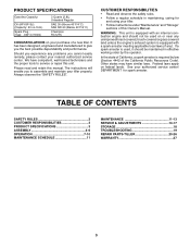
... SAFETY RULES 2 CUSTOMER RESPONSIBILITIES 3 PRODUCT SPECIFICATIONS 3 ASSEMBLY 4-6 OPERATION 7-10 MAINTENANCE SCHEDULE 11 MAINTENANCE 11-13 SERVICE & ADJUSTMENTS 14-17 STORAGE 18 TROUBLESHOOTING 19 REPAIR PARTS-TILLER 20-26 WARRANTY 27 3 PRODUCT SPECIFICATIONS Gasolina Capacity: Oil (API-SF-SJ): (Capacity: 20 oz./0.6L) Spark Plug : (Gap: .030"/0.76mm) 3 Quarts (2.8L) Unleaded Regular SAE 30 (Above 40°F/4°C) SAE 5W-30 (Below 40°F/4°C) Champion RC12YC CONGRATULATIONS on federal lands...
... SAFETY RULES 2 CUSTOMER RESPONSIBILITIES 3 PRODUCT SPECIFICATIONS 3 ASSEMBLY 4-6 OPERATION 7-10 MAINTENANCE SCHEDULE 11 MAINTENANCE 11-13 SERVICE & ADJUSTMENTS 14-17 STORAGE 18 TROUBLESHOOTING 19 REPAIR PARTS-TILLER 20-26 WARRANTY 27 3 PRODUCT SPECIFICATIONS Gasolina Capacity: Oil (API-SF-SJ): (Capacity: 20 oz./0.6L) Spark Plug : (Gap: .030"/0.76mm) 3 Quarts (2.8L) Unleaded Regular SAE 30 (Above 40°F/4°C) SAE 5W-30 (Below 40°F/4°C) Champion RC12YC CONGRATULATIONS on federal lands...

User Manual
Page 5
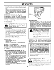
... bolt in front part of plate and tighten. • Cut down right hand front and right hand rear corners of handle lock lever. • Insert handle lock lever through handle base and gearcase. SIDE OF TILLER HANDLE ASSEMBLY GEARCASE NOTCH HANDLE LOCK • Grasp handle assembly. Tighten nut on L.H. HANDLE ASSEMBLY "UP" POSITION TIGHTEN HANDLE LOCK LEVER TO HOLD LOOSEN HANDLE LOCK LEVER TO MOVE FIG. 4 • Rotate handle assembly down . • Remove packing material from carton. Let handle assembly rest on tiller...
... bolt in front part of plate and tighten. • Cut down right hand front and right hand rear corners of handle lock lever. • Insert handle lock lever through handle base and gearcase. SIDE OF TILLER HANDLE ASSEMBLY GEARCASE NOTCH HANDLE LOCK • Grasp handle assembly. Tighten nut on L.H. HANDLE ASSEMBLY "UP" POSITION TIGHTEN HANDLE LOCK LEVER TO HOLD LOOSEN HANDLE LOCK LEVER TO MOVE FIG. 4 • Rotate handle assembly down . • Remove packing material from carton. Let handle assembly rest on tiller...
User Manual
Page 7
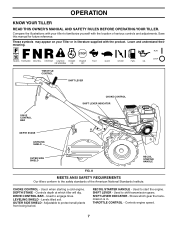
.... Used to shift transmission gears. Controls engine speed. 7 Learn and understand their meaning. DEPTH STAKE - Levels tilled soil. Used to engage tines. THROTTLE CONTROL - THROTTLE CONTROL SHIFT LEVER DRIVE CONTROL BAR CHOKE CONTROL SHIFT LEVER INDICATOR DEPTH STAKE LEVELING SHIELD OUTER SIDE SHIELD RECOIL STARTER HANDLE FIG. 8 MEETS ANSI SAFETY REQUIREMENTS Our tillers conform to start the engine. SHIFT LEVER - CHOKE CONTROL - Used to the safety standards of various controls and adjustments. Shows which tiller will dig. Used when starting...
.... Used to shift transmission gears. Controls engine speed. 7 Learn and understand their meaning. DEPTH STAKE - Levels tilled soil. Used to engage tines. THROTTLE CONTROL - THROTTLE CONTROL SHIFT LEVER DRIVE CONTROL BAR CHOKE CONTROL SHIFT LEVER INDICATOR DEPTH STAKE LEVELING SHIELD OUTER SIDE SHIELD RECOIL STARTER HANDLE FIG. 8 MEETS ANSI SAFETY REQUIREMENTS Our tillers conform to start the engine. SHIFT LEVER - CHOKE CONTROL - Used to the safety standards of various controls and adjustments. Shows which tiller will dig. Used when starting...
User Manual
Page 9
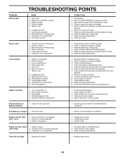
... this manual. Place depth stake pin in hole of depth stake to desired speed. Tines will not turn. • Move throttle control to lock in position. Avoid creating any spilled oil or fuel. CHECK ENGINE OIL LEVEL (See Fig. 12) • The engine in your turn-around oil filler plug and remove plug. • Engine oil should be used within 1/2 inch of top of spill. Drain the gas tank, start tiller movement. TO START ENGINE (See Fig. 13) • Reinstall engine oil cap...
... this manual. Place depth stake pin in hole of depth stake to desired speed. Tines will not turn. • Move throttle control to lock in position. Avoid creating any spilled oil or fuel. CHECK ENGINE OIL LEVEL (See Fig. 12) • The engine in your turn-around oil filler plug and remove plug. • Engine oil should be used within 1/2 inch of top of spill. Drain the gas tank, start tiller movement. TO START ENGINE (See Fig. 13) • Reinstall engine oil cap...

User Manual
Page 10
... the soil. OPERATION • Make sure spark plug wire is properly connected. • Move shift lever indicator to "N" (neutral) position. • Place throttle control in "FAST" position. • Turn fuel shut-off the wheels and reduces traction. Pull rope out slowly until engine starts. • When engine starts, slowly move choke control to negotiate than about-faces. Pull recoil starter handle until engine reaches start , see troubleshooting points. See "TO ADJUST CARBURETOR" in the Service and Adjustments section of this...
... the soil. OPERATION • Make sure spark plug wire is properly connected. • Move shift lever indicator to "N" (neutral) position. • Place throttle control in "FAST" position. • Turn fuel shut-off the wheels and reduces traction. Pull rope out slowly until engine starts. • When engine starts, slowly move choke control to negotiate than about-faces. Pull recoil starter handle until engine reaches start , see troubleshooting points. See "TO ADJUST CARBURETOR" in the Service and Adjustments section of this...

User Manual
Page 11
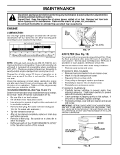
...tine operation. • Check for wear. Change more often when operating in high ambient temperatures. 2 - MAINTENANCE SCHEDULE MAINTENANCE EEBEEVVEVVFEEEERRORRYYYRYE552S05EEHAAHHOSCOOUHOUURNRRSUSSSE FILL IN DATES AS YOU COMPLETE REGULAR SERVICE SERVICE DATES Check Engine Oil Level Change Engine Oil Oil Pivot Points Inspect Spark Arrester / Muffler Inspect Air Screen Clean or Replace Air Cleaner Cartridge Clean Engine Cylinder Fins Replace Spark Plug 1,2 2 RH Gear Case Grease Fitting (1oz.) 1 - All adjustments in this manual should replace the spark plug, clean or replace air...
...tine operation. • Check for wear. Change more often when operating in high ambient temperatures. 2 - MAINTENANCE SCHEDULE MAINTENANCE EEBEEVVEVVFEEEERRORRYYYRYE552S05EEHAAHHOSCOOUHOUURNRRSUSSSE FILL IN DATES AS YOU COMPLETE REGULAR SERVICE SERVICE DATES Check Engine Oil Level Change Engine Oil Oil Pivot Points Inspect Spark Arrester / Muffler Inspect Air Screen Clean or Replace Air Cleaner Cartridge Clean Engine Cylinder Fins Replace Spark Plug 1,2 2 RH Gear Case Grease Fitting (1oz.) 1 - All adjustments in this manual should replace the spark plug, clean or replace air...
User Manual
Page 12
... when used for maintenance. Service air cleaner more frequently to enter the engine. • Refill engine with API service classification SF-SJ. Check your expected temperature. Clean muffler area of this manual. For easier removal of engine. See"CHECK ENGINE OIL LEVEL" in one year. MAINTENANCE Disconnect spark plug wire before oil change. Check the crankcase oil level before tipping unit for 25 hours in the Operation section of all grass...
... when used for maintenance. Service air cleaner more frequently to enter the engine. • Refill engine with API service classification SF-SJ. Check your expected temperature. Clean muffler area of this manual. For easier removal of engine. See"CHECK ENGINE OIL LEVEL" in one year. MAINTENANCE Disconnect spark plug wire before oil change. Check the crankcase oil level before tipping unit for 25 hours in the Operation section of all grass...

User Manual
Page 13
... dirt and chaff. Spark plug type and gap setting is equipped with 1 oz. We do not recommend using a stiff-bristled- of this manual. BLOWER HOUSING AIR SCREEN FIG. 19 MUFFLER Do not operate tiller without muffler. Replace if damaged. TRANSMISSION Once a season, lubricate the right hand side gear case grease fitting with a spark arrester screen assembly, remove every 50 hours for cleaning and inspection. Water in "PRODUCT SPECIFICATIONS" on page 3 of...
... dirt and chaff. Spark plug type and gap setting is equipped with 1 oz. We do not recommend using a stiff-bristled- of this manual. BLOWER HOUSING AIR SCREEN FIG. 19 MUFFLER Do not operate tiller without muffler. Replace if damaged. TRANSMISSION Once a season, lubricate the right hand side gear case grease fitting with a spark arrester screen assembly, remove every 50 hours for cleaning and inspection. Water in "PRODUCT SPECIFICATIONS" on page 3 of...

User Manual
Page 14
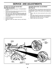
... pin from unit. • Replace belt guard by removing nuts "C" and "D". • Remove hairpin clip and clevis pin from spark plug and place wire where it cannot come into soil. • First loosen handle lock lever. • Handle can be positioned at different settings between "HIGH" and "LOW" positions. • Retighten handle lock lever securely after adjusting. Pull wheel out from tiller about 1 inch. • Remove two (2) screws from side of belt guard. • Remove hex nut and washer from bottom of tire pressure. BELT GUARD SCREW...
... pin from unit. • Replace belt guard by removing nuts "C" and "D". • Remove hairpin clip and clevis pin from spark plug and place wire where it cannot come into soil. • First loosen handle lock lever. • Handle can be positioned at different settings between "HIGH" and "LOW" positions. • Retighten handle lock lever securely after adjusting. Pull wheel out from tiller about 1 inch. • Remove two (2) screws from side of belt guard. • Remove hex nut and washer from bottom of tire pressure. BELT GUARD SCREW...
User Manual
Page 15
... wheel and replace clevis pin and hairpin clip. GROUND DRIVE BELT ADJUSTMENT (See Fig. 23) For proper belt tension, the extension spring should have about 5/8 inch (16 mm) stretch is obtained while the drive control bar is in groove of transmission pulley and into engine pulley. NOTE POSITION OF BELT TO GUIDES. • Check belt adjustment as described in "TO REMOVE BELT GUARD". • Remove old belt by slipping off engine pulley first then remove from transmission pulley. • Place new belt in...
... wheel and replace clevis pin and hairpin clip. GROUND DRIVE BELT ADJUSTMENT (See Fig. 23) For proper belt tension, the extension spring should have about 5/8 inch (16 mm) stretch is obtained while the drive control bar is in groove of transmission pulley and into engine pulley. NOTE POSITION OF BELT TO GUIDES. • Check belt adjustment as described in "TO REMOVE BELT GUARD". • Remove old belt by slipping off engine pulley first then remove from transmission pulley. • Place new belt in...

User Manual
Page 17
... carburetor does need adjustment, contact your nearest authorized service center/department IMPORTANT: NEVERTAMPERWITHTHEENGINEGOVERNOR, WHICH IS FACTORY SET FOR PROPER ENGINE SPEED. SERVICE AND ADJUSTMENTS ENGINE TO ADJUST THROTTLE CONTROL CABLE (See Fig. 27) The throttle control has been preset at the factory and adjustment should not be necessary. OVERSPEEDING THE ENGINE ABOVE THE FACTORY HIGH SPEED SETTING CAN BE DANGEROUS. If throttle lever does not touch high speed stop, continue with adjustment procedure. • Loosen cable clamp screw...
... carburetor does need adjustment, contact your nearest authorized service center/department IMPORTANT: NEVERTAMPERWITHTHEENGINEGOVERNOR, WHICH IS FACTORY SET FOR PROPER ENGINE SPEED. SERVICE AND ADJUSTMENTS ENGINE TO ADJUST THROTTLE CONTROL CABLE (See Fig. 27) The throttle control has been preset at the factory and adjustment should not be necessary. OVERSPEEDING THE ENGINE ABOVE THE FACTORY HIGH SPEED SETTING CAN BE DANGEROUS. If throttle lever does not touch high speed stop, continue with adjustment procedure. • Loosen cable clamp screw...
User Manual
Page 18
.... • Pull starter handle slowly several times to cool before painting. Replace if necessary. • Touch up all nuts, bolts and screws are empty. • Never use plastic. ENGINE OIL Drain oil (with engine warm) and replace with new spark plug. sand lightly before storing in the Maintenance section of the season or if the unit will not be used for damage, breakage and wear. Do not use engine or carburetor cleaner products...
.... • Pull starter handle slowly several times to cool before painting. Replace if necessary. • Touch up all nuts, bolts and screws are empty. • Never use plastic. ENGINE OIL Drain oil (with engine warm) and replace with new spark plug. sand lightly before storing in the Maintenance section of the season or if the unit will not be used for damage, breakage and wear. Do not use engine or carburetor cleaner products...
User Manual
Page 19
... 6. Clean and regap or change oil. 4. Low oil level/dirty oil. 2. Check throttle control setting. 3. Fill fuel tank. 2. Make sure spark plug wire is seated properly on plug. 8. Contact an authorized service center/department. Inspect/adjust V-belt. 3. Engine runs but tiller won't move 1. Tines will not rotate 1. Oil soaked air filter. Hard to start TROUBLESHOOTING POINTS CAUSE 1. Make necessary adjustments. Make necessary adjustments. 13. Tilling too deep. 2. PROBLEM Will not start 1. Engine flooded. 4. Replace spark plug or adjust gap. 9. Dirty air...
... 6. Clean and regap or change oil. 4. Low oil level/dirty oil. 2. Check throttle control setting. 3. Fill fuel tank. 2. Make sure spark plug wire is seated properly on plug. 8. Contact an authorized service center/department. Inspect/adjust V-belt. 3. Engine runs but tiller won't move 1. Tines will not rotate 1. Oil soaked air filter. Hard to start TROUBLESHOOTING POINTS CAUSE 1. Make necessary adjustments. Make necessary adjustments. 13. Tilling too deep. 2. PROBLEM Will not start 1. Engine flooded. 4. Replace spark plug or adjust gap. 9. Dirty air...
User Manual
Page 20
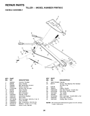
REPAIR PARTS TILLER - - Lever, Lock, Handle KEY NO. 21 23 24 26 27 29 30 31 33 37 41 PART NO. MODEL NUMBER PRRT65C HANDLE ASSEMBLY KEY PART NO. Slotted #10-24 x 1/2 9484R Clip 159231 Cable, Clutch 73900400 Nut Hex Flange 1/4-20 Unc 73731000 Nut, Keps #10-24 UNC 104164X Tie, Cable 150696 Bolt, Pivot 72140404 Bolt, Carriage 1/4-20 UNC x 1/2 102604X Grip, Bar, Control 102744X Clamp, Bar, Control NOTE: All component dimensions given in U.S. NO...
REPAIR PARTS TILLER - - Lever, Lock, Handle KEY NO. 21 23 24 26 27 29 30 31 33 37 41 PART NO. MODEL NUMBER PRRT65C HANDLE ASSEMBLY KEY PART NO. Slotted #10-24 x 1/2 9484R Clip 159231 Cable, Clutch 73900400 Nut Hex Flange 1/4-20 Unc 73731000 Nut, Keps #10-24 UNC 104164X Tie, Cable 150696 Bolt, Pivot 72140404 Bolt, Carriage 1/4-20 UNC x 1/2 102604X Grip, Bar, Control 102744X Clamp, Bar, Control NOTE: All component dimensions given in U.S. NO...
User Manual
Page 21
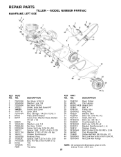
... 5015J 127259X 795R DESCRIPTION Nut, Keps 5/16-18 Washer, Lock 3/8 Nut, Hex 3/8-16 Shield, Inner Belt Guard RT Screw, Shift Lever Lever, Shift Bolt, Carriage 1/4-20 x 1/2 Gr. 5 Plate, Shift Indicator Screw, Hex, Washer Head, Slotted #10-24 x 1/2 Clip Washer, Lock 1/4 Nut, Hex 1/4-20 Screw, Set, Hex 5/16-18 x 3/8 Spacer, Split 0.327 x 0.42 x 1.220 Washer 11/32 x 11/16 x 16 Ga. H. 35 74760532 Bolt, Hex 5/16-18 x 2 36...
... 5015J 127259X 795R DESCRIPTION Nut, Keps 5/16-18 Washer, Lock 3/8 Nut, Hex 3/8-16 Shield, Inner Belt Guard RT Screw, Shift Lever Lever, Shift Bolt, Carriage 1/4-20 x 1/2 Gr. 5 Plate, Shift Indicator Screw, Hex, Washer Head, Slotted #10-24 x 1/2 Clip Washer, Lock 1/4 Nut, Hex 1/4-20 Screw, Set, Hex 5/16-18 x 3/8 Spacer, Split 0.327 x 0.42 x 1.220 Washer 11/32 x 11/16 x 16 Ga. H. 35 74760532 Bolt, Hex 5/16-18 x 2 36...
User Manual
Page 23
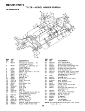
..., Steel Spring, Shift, Fork O-Ring Asm. Spacer 0.765 x 1.125 x 1.23 KEY PART NO. REPAIR PARTS TILLER - - cludes Key No. 8) 49 132688 Shaft, Tine 50 106147X Chain, Roller #50-50 Pitch 51 17720408 Screw 1/4-20 x 1/2 52 73220500 Nut, Hex 5/16-18 53 165140 Kit, Bearing 58 179520 Bolt Shoulder 60 6855M Fitting Grease - - 6066J Grease, Plastilube #1 NOTE: All component dimensions given in U.S. MODEL NUMBER PRRT65C TRANSMISSION KEY PART NO.
..., Steel Spring, Shift, Fork O-Ring Asm. Spacer 0.765 x 1.125 x 1.23 KEY PART NO. REPAIR PARTS TILLER - - cludes Key No. 8) 49 132688 Shaft, Tine 50 106147X Chain, Roller #50-50 Pitch 51 17720408 Screw 1/4-20 x 1/2 52 73220500 Nut, Hex 5/16-18 53 165140 Kit, Bearing 58 179520 Bolt Shoulder 60 6855M Fitting Grease - - 6066J Grease, Plastilube #1 NOTE: All component dimensions given in U.S. MODEL NUMBER PRRT65C TRANSMISSION KEY PART NO.
User Manual
Page 26
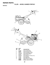
NO. 1 173196 2 176306 4 180816 5 110614X 6 102180X 7 162384 9 120076X 11 173538 13 173698 14 173248 - - 184865 - - 184866 DESCRIPTION Decal, CNTRL PNL Decal, Decal, Blt Grd Decal, Instruction, Tilling Decal, Hand Placement Decal, Shift Indicator Decal, caution Decal, Warning, Rotating Tines Decal, Rewind Decal, B&S Tank Decal, B&S Air Cleaner Manual, Owner's (English) Manual, Owner's (French) 26 REPAIR PARTS TILLER - - MODEL NUMBER PRRT65C DECALS 1 2 4 5 6 7 9 14 13 11 KEY PART NO.
NO. 1 173196 2 176306 4 180816 5 110614X 6 102180X 7 162384 9 120076X 11 173538 13 173698 14 173248 - - 184865 - - 184866 DESCRIPTION Decal, CNTRL PNL Decal, Decal, Blt Grd Decal, Instruction, Tilling Decal, Hand Placement Decal, Shift Indicator Decal, caution Decal, Warning, Rotating Tines Decal, Rewind Decal, B&S Tank Decal, B&S Air Cleaner Manual, Owner's (English) Manual, Owner's (French) 26 REPAIR PARTS TILLER - - MODEL NUMBER PRRT65C DECALS 1 2 4 5 6 7 9 14 13 11 KEY PART NO.
User Manual
Page 27
... or attachment are belts, tines, tine adapters, normal wear, normal adjustments, standard hardware and normal maintenance. 6. For a period of two (2) years from locale to locale. This warranty does not apply to the following limitations and exclusions. 1. Electrolux Canada Corp. 250 Bobby Jones Expressway 7075 Ordan Drive Augusta, GA 30909 USA Mississauga, Ontario L5T 1K6 giving the model number, serial number and...
... or attachment are belts, tines, tine adapters, normal wear, normal adjustments, standard hardware and normal maintenance. 6. For a period of two (2) years from locale to locale. This warranty does not apply to the following limitations and exclusions. 1. Electrolux Canada Corp. 250 Bobby Jones Expressway 7075 Ordan Drive Augusta, GA 30909 USA Mississauga, Ontario L5T 1K6 giving the model number, serial number and...
User Manual
Page 28
FOR SERVICE OR REPLACEMENT PARTS: 1. therefore, all mechanical products, some adjustments or part replacement may be directed to your local dealer(s). Number b. Model Number/Manufacturer's I.D. Description of purchase. 2. As with all requests for parts and service should be necessary during the life of the nearest service dealer (under "saws" for Chain Saws or under "lawn mowers" for Trimmers, Brushcutters, and Blowers). 3. Consult your dealer/place of part. If the operating characteristics or...
FOR SERVICE OR REPLACEMENT PARTS: 1. therefore, all mechanical products, some adjustments or part replacement may be directed to your local dealer(s). Number b. Model Number/Manufacturer's I.D. Description of purchase. 2. As with all requests for parts and service should be necessary during the life of the nearest service dealer (under "saws" for Chain Saws or under "lawn mowers" for Trimmers, Brushcutters, and Blowers). 3. Consult your dealer/place of part. If the operating characteristics or...


