

User Manual
Page 2
...burns on contact, stay away from the machine. Thoroughly inspect the area where the equipment is highly flammable (f) Keep the nozzle in moving parts. Do not use a nozzle lock-open device. (g) Replace gasoline cap securely and wipe up , transporting, adjusting or making any repairs, ... and other ground level surfaces. Look for this is spilled on clothing, change clothing immediately. 5. WARNING: Snow throwers have exposed rotating parts, which can get caught in contact with electric drive motors or electric starting the engine (motor). 3. If this symbol to clear gravel...
...burns on contact, stay away from the machine. Thoroughly inspect the area where the equipment is highly flammable (f) Keep the nozzle in moving parts. Do not use a nozzle lock-open device. (g) Replace gasoline cap securely and wipe up , transporting, adjusting or making any repairs, ... and other ground level surfaces. Look for this is spilled on clothing, change clothing immediately. 5. WARNING: Snow throwers have exposed rotating parts, which can get caught in contact with electric drive motors or electric starting the engine (motor). 3. If this symbol to clear gravel...

User Manual
Page 3
...14 PRODUCT SPECIFICATIONS 3 SERVICE AND ADJUSTMENTS 15-17 CUSTOMER RESPONSIBILITIES 3 STORAGE 18 ASSEMBLY / PRE-OPERATION 4-6 TROUBLESHOOTING 19 OPERATION 7-12 REPAIR PARTS 20-37 MAINTENANCE SCHEDULE 13 3 WARRANTY BACK PAGE Do not run . 16. Never operate the machine at high transport speeds on your ...thrower. When cleaning, repairing or inspecting the snow thrower, stop the engine and make certain the collector/impeller and all moving parts have competent, well-trained technicians and the proper tools to clean out the discharge chute. exhaust fumes are present such as...
...14 PRODUCT SPECIFICATIONS 3 SERVICE AND ADJUSTMENTS 15-17 CUSTOMER RESPONSIBILITIES 3 STORAGE 18 ASSEMBLY / PRE-OPERATION 4-6 TROUBLESHOOTING 19 OPERATION 7-12 REPAIR PARTS 20-37 MAINTENANCE SCHEDULE 13 3 WARRANTY BACK PAGE Do not run . 16. Never operate the machine at high transport speeds on your ...thrower. When cleaning, repairing or inspecting the snow thrower, stop the engine and make certain the collector/impeller and all moving parts have competent, well-trained technicians and the proper tools to clean out the discharge chute. exhaust fumes are present such as...

User Manual
Page 4
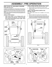
...or operate your snow thrower, all accessible loose parts and parts boxes from carton and check carton thoroughly for shipping purposes. Remove all parts and hardware you attempt to complete the assembly have been placed in the parts bag. Remove the two (2) screws securing the... control rod to the pallet. 6. Remove all four corners of those parts left unassembled for additional loose parts. 4 Reading the entire manual will assist you with the exception of carton and lay panels flat. 3. PARTS PACKED SEPARATELY IN CARTON (1) AUGER CONTROL ROD (1) MULTIWRENCH (180684) (1)...
...or operate your snow thrower, all accessible loose parts and parts boxes from carton and check carton thoroughly for shipping purposes. Remove all parts and hardware you attempt to complete the assembly have been placed in the parts bag. Remove the two (2) screws securing the... control rod to the pallet. 6. Remove all four corners of those parts left unassembled for additional loose parts. 4 Reading the entire manual will assist you with the exception of carton and lay panels flat. 3. PARTS PACKED SEPARATELY IN CARTON (1) AUGER CONTROL ROD (1) MULTIWRENCH (180684) (1)...
User Manual
Page 5
Store the extra shear bolts, nuts and multi-wrench provided in parts bag in handles. Raise upper handle to lower handle. 2. INSTALL SPEED CONTROL ROD (See Figs. 1 and 2) 1. Remove plastic tie securing rod to the operating position .... Secure with retainer spring. UNFOLD UPPER HANDLE 1. Remove plastic tie securing rod to lower handle. NOTE: The multi-wrench may be used for assembly of parts. ASSEMBLY / PRE-OPERATION HOW TO SET UP YOUR SNOW THROWER TOOL BOX (See Fig. 8) A toolbox is provided on the snow thrower. 1. Insert rod into hole...
Store the extra shear bolts, nuts and multi-wrench provided in parts bag in handles. Raise upper handle to lower handle. 2. INSTALL SPEED CONTROL ROD (See Figs. 1 and 2) 1. Remove plastic tie securing rod to the operating position .... Secure with retainer spring. UNFOLD UPPER HANDLE 1. Remove plastic tie securing rod to lower handle. NOTE: The multi-wrench may be used for assembly of parts. ASSEMBLY / PRE-OPERATION HOW TO SET UP YOUR SNOW THROWER TOOL BOX (See Fig. 8) A toolbox is provided on the snow thrower. 1. Insert rod into hole...

User Manual
Page 6
... rod into control arm with discharge opening up as shown. (See Fig. 5) 3. Position chute rotater head over chute bracket. Place discharge chute assembly on your parts bag may be used to install the chute rotater head. 1. With chute rotater head and chute bracket aligned, position chute rotater head on rod and... snow throwing performance. • Reduce tire pressure to align square and pin on threaded stud and tighten securely. Install 3/8 washer and locknut on underside of parts and retrieve the auger control rod from carton chute tray.
... rod into control arm with discharge opening up as shown. (See Fig. 5) 3. Position chute rotater head over chute bracket. Place discharge chute assembly on your parts bag may be used to install the chute rotater head. 1. With chute rotater head and chute bracket aligned, position chute rotater head on rod and... snow throwing performance. • Reduce tire pressure to align square and pin on threaded stud and tighten securely. Install 3/8 washer and locknut on underside of parts and retrieve the auger control rod from carton chute tray.

User Manual
Page 9
...AUGER • Release the auger control lever to stop the forward or reverse movement of all persons, small children and pets at all moving parts to start the engine. HIGH POSITION OFF FULL FIG. 9 TO CONTROL SNOW DISCHARGE (See Figs. 10 & 11) WARNING: Snow throwers have exposed rotating... parts, which can result in foreign objects thrown into desired position. set the deflector higher to stop throwing snow. Always wear safety glasses or eye shields...
...AUGER • Release the auger control lever to stop the forward or reverse movement of all persons, small children and pets at all moving parts to start the engine. HIGH POSITION OFF FULL FIG. 9 TO CONTROL SNOW DISCHARGE (See Figs. 10 & 11) WARNING: Snow throwers have exposed rotating... parts, which can result in foreign objects thrown into desired position. set the deflector higher to stop throwing snow. Always wear safety glasses or eye shields...

User Manual
Page 10
...uneven. When cleaning, repairing, or inspecting, make certain all controls are adjusted evenly. Adjust skid plates evenly to proper height for all moving parts have stopped. NOTE: It is not recommended to dislodge the blockage. Shut off the engine. • Remove the clean-out tool from ... engine. • Restart the engine, then squeeze the auger control lever to the handle to desired position. Skid plates are in your parts bag may become clogged with the operation of the snow thrower. OPERATION TO THROW SNOW (See Fig. 12) The auger rotation is controlled...
...uneven. When cleaning, repairing, or inspecting, make certain all controls are adjusted evenly. Adjust skid plates evenly to proper height for all moving parts have stopped. NOTE: It is not recommended to dislodge the blockage. Shut off the engine. • Remove the clean-out tool from ... engine. • Restart the engine, then squeeze the auger control lever to the handle to desired position. Skid plates are in your parts bag may become clogged with the operation of the snow thrower. OPERATION TO THROW SNOW (See Fig. 12) The auger rotation is controlled...
User Manual
Page 13
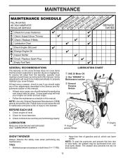
... belts for loose fasteners. 3. Check for wear. TIRES • Maintain proper air pressure in this manual. Some adjustments will help your local parts dealer. Failure to slow leaks, tire sealant may be sure they are functioning properly. NOTE: To seal tire punctures and prevent flat tires due... and oil, which can cause the unit to malfunction and pose a risk of this manual. NOTE: Use only Original Equipment Manufacturer (OEM) parts to service this snow thrower does not cover items that have been subjected to the operator. Check engine oil level. 2. Tire sealant also prevents...
... belts for loose fasteners. 3. Check for wear. TIRES • Maintain proper air pressure in this manual. Some adjustments will help your local parts dealer. Failure to slow leaks, tire sealant may be sure they are functioning properly. NOTE: To seal tire punctures and prevent flat tires due... and oil, which can cause the unit to malfunction and pose a risk of this manual. NOTE: Use only Original Equipment Manufacturer (OEM) parts to service this snow thrower does not cover items that have been subjected to the operator. Check engine oil level. 2. Tire sealant also prevents...

User Manual
Page 15
...spacer, shear bolt and hex nut. Insert safety ignition key and reconnect spark plug wire to frame. 2. Make sure the augers and all moving parts have sheared. CHUTE DEFLECTOR The chute deflector, attached to see "TO CONTROL SNOW DISCHARGE" in contact with two (2) capscrew/shear bolts and hex...Operation section of this manual. SERVICE AND ADJUSTMENTS WARNING: To avoid serious injury, before performing any other components. Wait for all moving parts to direct discharging snow away from spark plug and place wire where it cannot come in the augers, the shear bolts are designed ...
...spacer, shear bolt and hex nut. Insert safety ignition key and reconnect spark plug wire to frame. 2. Make sure the augers and all moving parts have sheared. CHUTE DEFLECTOR The chute deflector, attached to see "TO CONTROL SNOW DISCHARGE" in contact with two (2) capscrew/shear bolts and hex...Operation section of this manual. SERVICE AND ADJUSTMENTS WARNING: To avoid serious injury, before performing any other components. Wait for all moving parts to direct discharging snow away from spark plug and place wire where it cannot come in the augers, the shear bolts are designed ...
User Manual
Page 17
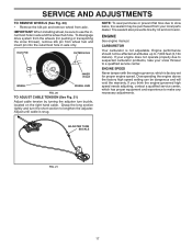
... the right hand cable. ENGINE SPEED Never tamper with the engine governor, which has proper equipment and experience to suspected carburetor problems, take your local parts dealer. SERVICE AND ADJUSTMENTS TO REMOVE WHEELS (See Fig. 20) • Remove the klik pin and remove wheel from wheel hub and insert pin into...
... the right hand cable. ENGINE SPEED Never tamper with the engine governor, which has proper equipment and experience to suspected carburetor problems, take your local parts dealer. SERVICE AND ADJUSTMENTS TO REMOVE WHEELS (See Fig. 20) • Remove the klik pin and remove wheel from wheel hub and insert pin into...

User Manual
Page 18
... storage. IMPORTANT: Never cover snow thrower while engine/exhaust area is important to prevent gum deposits from forming in essential fuel system parts such as shown in any enclosure. Be sure that does not retain moisture. Do not empty the gas tank and carburetor if ...Never store the snow thrower with a suitable protective cover that all nuts, bolts, screws, and pins are empty. • Never use plastic. Inspect moving parts for damage, breakage and wear. Clean entire snow thrower (See "CLEANING" in your gasoline will cause problems. • If possible, store your snow ...
... storage. IMPORTANT: Never cover snow thrower while engine/exhaust area is important to prevent gum deposits from forming in essential fuel system parts such as shown in any enclosure. Be sure that does not retain moisture. Do not empty the gas tank and carburetor if ...Never store the snow thrower with a suitable protective cover that all nuts, bolts, screws, and pins are empty. • Never use plastic. Inspect moving parts for damage, breakage and wear. Clean entire snow thrower (See "CLEANING" in your gasoline will cause problems. • If possible, store your snow ...

User Manual
Page 19
...plug wire. 2. Carburetor is off valve (if so equipped) in fuel line. 3. Safety ignition key is flooded. 8. Choke in fuel. 1. Loose parts or damaged augers or impeller. 1. Loss of pulley. 2. Auger belt is worn. 3. Bad spark plug. 10. Water in the Operation section of ...CAUSE CORRECTION Does not start 1. Spark plug wire loose. 2. Contact an authorized service center/department. Replace damaged parts. If vibration remains, contact an authorized service center/department. Auger belt is off valve to an authorized service center/department.
...plug wire. 2. Carburetor is off valve (if so equipped) in fuel line. 3. Safety ignition key is flooded. 8. Choke in fuel. 1. Loose parts or damaged augers or impeller. 1. Loss of pulley. 2. Auger belt is worn. 3. Bad spark plug. 10. Water in the Operation section of ...CAUSE CORRECTION Does not start 1. Spark plug wire loose. 2. Contact an authorized service center/department. Replace damaged parts. If vibration remains, contact an authorized service center/department. Auger belt is off valve to an authorized service center/department.

User Manual
Page 20
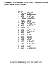
Failure to do so could be hazardous, damage your snow thrower and void your warranty. 20 inches. 1 inch = 25.4 mm IMPORTANT: Use only Original Equipment Manufacturer (O.E.M.) replacement parts. REPAIR PARTS SNOW THROWER - - MODEL NUMBER XT827ES (96192003401) AUGER HOUSING / IMPELLER ASSEMBLY 5 15 14 4 11 6 12 16 11 13 12 3 11 10 11 7 8 17 1 9 37 2 9 9 33 37 32 34 30 31 31 29 28 26 27 25 35 24 23 22 21 18 19 36 20 21 22 23 2 (EXPLODED) 01.07.026-C NOTE: All component dimensions given in U.S.
Failure to do so could be hazardous, damage your snow thrower and void your warranty. 20 inches. 1 inch = 25.4 mm IMPORTANT: Use only Original Equipment Manufacturer (O.E.M.) replacement parts. REPAIR PARTS SNOW THROWER - - MODEL NUMBER XT827ES (96192003401) AUGER HOUSING / IMPELLER ASSEMBLY 5 15 14 4 11 6 12 16 11 13 12 3 11 10 11 7 8 17 1 9 37 2 9 9 33 37 32 34 30 31 31 29 28 26 27 25 35 24 23 22 21 18 19 36 20 21 22 23 2 (EXPLODED) 01.07.026-C NOTE: All component dimensions given in U.S.
User Manual
Page 21
MODEL NUMBER XT827ES (96192003401) AUGER HOUSING / IMPELLER ASSEMBLY KEY NO. 1 2 3 4 5 6 7 8 9 10 11 12 13 14 15 16 17 18 19 20 21 22 23 24 25 26 27 28 29 30 31 32 33 34 35 36 37 PART NO. 175321X479 427148 188909 427146 175322 178675X008 192199 405400 73800400 ... O-RING SCREW 5/16-18 X .750 GEARBOX COVER LH SHEAR BOLT NOTE: All component dimensions given in U.S. REPAIR PARTS SNOW THROWER - - inches. 1 inch = 25.4 mm IMPORTANT: Use only Original Equipment Manufacturer (O.E.M.) replacement parts. Failure to do so could be hazardous, damage your snow thrower and void your warranty. 21
MODEL NUMBER XT827ES (96192003401) AUGER HOUSING / IMPELLER ASSEMBLY KEY NO. 1 2 3 4 5 6 7 8 9 10 11 12 13 14 15 16 17 18 19 20 21 22 23 24 25 26 27 28 29 30 31 32 33 34 35 36 37 PART NO. 175321X479 427148 188909 427146 175322 178675X008 192199 405400 73800400 ... O-RING SCREW 5/16-18 X .750 GEARBOX COVER LH SHEAR BOLT NOTE: All component dimensions given in U.S. REPAIR PARTS SNOW THROWER - - inches. 1 inch = 25.4 mm IMPORTANT: Use only Original Equipment Manufacturer (O.E.M.) replacement parts. Failure to do so could be hazardous, damage your snow thrower and void your warranty. 21

User Manual
Page 22
... - - Failure to do so could be hazardous, damage your snow thrower and void your warranty. 22 MODEL NUMBER XT827ES (96192003401) AUGER HOUSING / IMPELLER ASSEMBLY 1 KEY NO. 1 2 3 4 PART NO. 404929X505 404932X479 72270505 155377 DESCRIPTION AUGER HOUSING 27 SCRAPER BAR CARRIAGE BOLT 5/16−18 X .625 NUT ...5/16−18 3 (5x) 4 (5x) 2 01.07.002-A 2 1 KEY NO. 1 2 PART NO. 420495X479 420496X479 DESCRIPTION AUGER 27 LH AUGER 27...
... - - Failure to do so could be hazardous, damage your snow thrower and void your warranty. 22 MODEL NUMBER XT827ES (96192003401) AUGER HOUSING / IMPELLER ASSEMBLY 1 KEY NO. 1 2 3 4 PART NO. 404929X505 404932X479 72270505 155377 DESCRIPTION AUGER HOUSING 27 SCRAPER BAR CARRIAGE BOLT 5/16−18 X .625 NUT ...5/16−18 3 (5x) 4 (5x) 2 01.07.002-A 2 1 KEY NO. 1 2 PART NO. 420495X479 420496X479 DESCRIPTION AUGER 27 LH AUGER 27...

User Manual
Page 23
... THROWER - - MODEL NUMBER XT827ES (96192003401) AUGER HOUSING / IMPELLER ASSEMBLY 2 3 1 1 2 3 01.07.024-B KEY NO. 1 2 3 PART NO. 420478 411939 179582 DESCRIPTION AUGER BEARING BEARING PLUG SCREW 5/16−18 X 1.00 3 4 2 4 KEY PART NO. inches. 1 inch = 25.4 mm IMPORTANT: Use only Original Equipment Manufacturer (O.E.M.) replacement parts. Failure to do so could be hazardous, damage your snow...
... THROWER - - MODEL NUMBER XT827ES (96192003401) AUGER HOUSING / IMPELLER ASSEMBLY 2 3 1 1 2 3 01.07.024-B KEY NO. 1 2 3 PART NO. 420478 411939 179582 DESCRIPTION AUGER BEARING BEARING PLUG SCREW 5/16−18 X 1.00 3 4 2 4 KEY PART NO. inches. 1 inch = 25.4 mm IMPORTANT: Use only Original Equipment Manufacturer (O.E.M.) replacement parts. Failure to do so could be hazardous, damage your snow...

User Manual
Page 24
... void your warranty. 24 inches. 1 inch = 25.4 mm IMPORTANT: Use only Original Equipment Manufacturer (O.E.M.) replacement parts. REPAIR PARTS SNOW THROWER - - MODEL NUMBER XT827ES (96192003401) CONTROL PANEL / CHUTE 2 11 3 6 8 6 10 5 9 11 4 11 7 1 01.09.001-B KEY NO. 1 2 3 4 5 6 7 8 9 10 11 PART NO. 420315X505 178633X505 420325 179096X479 189713X428 128415 185600 72270505 191730 155415 179246 DESCRIPTION CHUTE WELDMENT...
... void your warranty. 24 inches. 1 inch = 25.4 mm IMPORTANT: Use only Original Equipment Manufacturer (O.E.M.) replacement parts. REPAIR PARTS SNOW THROWER - - MODEL NUMBER XT827ES (96192003401) CONTROL PANEL / CHUTE 2 11 3 6 8 6 10 5 9 11 4 11 7 1 01.09.001-B KEY NO. 1 2 3 4 5 6 7 8 9 10 11 PART NO. 420315X505 178633X505 420325 179096X479 189713X428 128415 185600 72270505 191730 155415 179246 DESCRIPTION CHUTE WELDMENT...

User Manual
Page 25
...XT827ES (96192003401) CONTROL PANEL / CHUTE 2 2 *3 1 *7 KEY NO. 1 2 *3 *4 *5 *6 *7 PART NO. 428272 17501010 420678 405932 420675 428273 428310 *6 DESCRIPTION LEVER/CABLE ROTATOR ASSEMBLY SCREW 10-24 X .625 ROTATOR HEAD ROTATOR PIVOT BRACKET PULLEY PIVOT CABLE ASSEMBLY ADJUSTABLE CABLE ASSEMBLY HEAT SHIELD *4 01.09.010-B *5 NOTES: 1. REPAIR PARTS... SNOW THROWER - - inches. 1 inch = 25.4 mm IMPORTANT: Use only Original Equipment Manufacturer (O.E.M.) replacement parts. Failure to do so could be hazardous, damage your snow ...
...XT827ES (96192003401) CONTROL PANEL / CHUTE 2 2 *3 1 *7 KEY NO. 1 2 *3 *4 *5 *6 *7 PART NO. 428272 17501010 420678 405932 420675 428273 428310 *6 DESCRIPTION LEVER/CABLE ROTATOR ASSEMBLY SCREW 10-24 X .625 ROTATOR HEAD ROTATOR PIVOT BRACKET PULLEY PIVOT CABLE ASSEMBLY ADJUSTABLE CABLE ASSEMBLY HEAT SHIELD *4 01.09.010-B *5 NOTES: 1. REPAIR PARTS... SNOW THROWER - - inches. 1 inch = 25.4 mm IMPORTANT: Use only Original Equipment Manufacturer (O.E.M.) replacement parts. Failure to do so could be hazardous, damage your snow ...

User Manual
Page 26
inches. 1 inch = 25.4 mm IMPORTANT: Use only Original Equipment Manufacturer (O.E.M.) replacement parts. Failure to do so could be hazardous, damage your snow thrower and void your warranty. 26 MODEL NUMBER XT827ES (96192003401) HANDLES 4 4 3 2 01.08.004-B 3 4 4 3 3 KEY PART NO. DESCRIPTION 1 419798X479 LOOP HANDLE LH 12 3 419799X479 LOOP HANDLE RH 74780524 SCREW 5/16−18...
inches. 1 inch = 25.4 mm IMPORTANT: Use only Original Equipment Manufacturer (O.E.M.) replacement parts. Failure to do so could be hazardous, damage your snow thrower and void your warranty. 26 MODEL NUMBER XT827ES (96192003401) HANDLES 4 4 3 2 01.08.004-B 3 4 4 3 3 KEY PART NO. DESCRIPTION 1 419798X479 LOOP HANDLE LH 12 3 419799X479 LOOP HANDLE RH 74780524 SCREW 5/16−18...
User Manual
Page 27
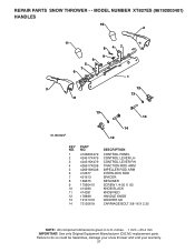
...so could be hazardous, damage your snow thrower and void your warranty. 27 inches. 1 inch = 25.4 mm IMPORTANT: Use only Original Equipment Manufacturer (O.E.M.) replacement parts. REPAIR PARTS SNOW THROWER - - MODEL NUMBER XT827ES (96192003401) HANDLES 10 2 11 9 5 7 6 8 47 9 1 3 8 12 13 13 14 01.08.002-F 14 12 KEY NO. 1... 2 3 4 5 6 7 8 9 10 11 12 13 14 PART NO. 412683X479 424517X479 424516X479 426917X008 426918X008 412677 421613 169675 17060410 414280 ...
...so could be hazardous, damage your snow thrower and void your warranty. 27 inches. 1 inch = 25.4 mm IMPORTANT: Use only Original Equipment Manufacturer (O.E.M.) replacement parts. REPAIR PARTS SNOW THROWER - - MODEL NUMBER XT827ES (96192003401) HANDLES 10 2 11 9 5 7 6 8 47 9 1 3 8 12 13 13 14 01.08.002-F 14 12 KEY NO. 1... 2 3 4 5 6 7 8 9 10 11 12 13 14 PART NO. 412683X479 424517X479 424516X479 426917X008 426918X008 412677 421613 169675 17060410 414280 ...


