
Owners Manual
Page 1
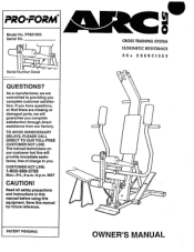
PRO FORM® Model No. The trained technicians on our customer hot line will guarantee you . Read all safety precautions and instructions in this manual before using this manual " for future reference. TO AVOID UNNECESSARY DELAYS, PLEASE CALL DIRECT TO OUR TOLL-FREE CUSTOMER HOT LINE. QUESTIONS? Save this equipment. PF851030 Serial No. ,o , . Serial Number Decal --- As a manufacturer, we are missing or damaged parts, we...
PRO FORM® Model No. The trained technicians on our customer hot line will guarantee you . Read all safety precautions and instructions in this manual before using this manual " for future reference. TO AVOID UNNECESSARY DELAYS, PLEASE CALL DIRECT TO OUR TOLL-FREE CUSTOMER HOT LINE. QUESTIONS? Save this equipment. PF851030 Serial No. ,o , . Serial Number Decal --- As a manufacturer, we are missing or damaged parts, we...

Owners Manual
Page 2
© 1993 Proform Fitness Products, Inc., a Subsidiary of Weider Health and Fitness, Inc. 2-
© 1993 Proform Fitness Products, Inc., a Subsidiary of Weider Health and Fitness, Inc. 2-
Owners Manual
Page 3
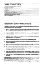
... 9. When using the cross training system. 1. Read all times. 5. If you feel pain or dizziness at all instructions in the accompanying literal the cross training system. PROFORM assumes no re: personal injury or property damage sustained by or through the use . TABLE OF CONTENTS IMPORTANT SAFETY PRECAUTIONS BEFORE YOU BEGIN PART CHART ASSEMBLY ADJUSTING THE CROSS TRAINING SYSTEM OPERATING THE CONSOLE TROUBLE-SHOOTING AND MAINTENANCE ORDERING REPLACEMENT PARTS LIMITED WARRANTY ' IMPORTANT...
... 9. When using the cross training system. 1. Read all times. 5. If you feel pain or dizziness at all instructions in the accompanying literal the cross training system. PROFORM assumes no re: personal injury or property damage sustained by or through the use . TABLE OF CONTENTS IMPORTANT SAFETY PRECAUTIONS BEFORE YOU BEGIN PART CHART ASSEMBLY ADJUSTING THE CROSS TRAINING SYSTEM OPERATING THE CONSOLE TROUBLE-SHOOTING AND MAINTENANCE ORDERING REPLACEMENT PARTS LIMITED WARRANTY ' IMPORTANT...
Owners Manual
Page 4
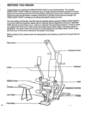
... you home. For your safety and benefit, read this owners manual for selecting the WESLOe BODY SHOP 2 cross training system. To help you to the WESLO BODY SHOP 2 (see the front cover of this manual carefully before calling. The serial number can be found on a decal attached to achieve the specific results you have additional questions, please call our Customer Service Department toll-free at...
... you home. For your safety and benefit, read this owners manual for selecting the WESLOe BODY SHOP 2 cross training system. To help you to the WESLO BODY SHOP 2 (see the front cover of this manual carefully before calling. The serial number can be found on a decal attached to achieve the specific results you have additional questions, please call our Customer Service Department toll-free at...
Owners Manual
Page 5
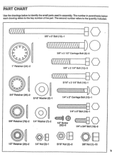
... parenthesis below to the key number of the part. ACM 1/2" Screw (52)-2 (\\\\\\\ 1/4" x 3/4" Bolt (18)-6 1/2" Retainer (26)-2 0 1/4" Nut (3)-1 5/16" Nut (2)-2 (0) 3/8" Nut (1)-10 PART CHART Use the drawings below each drawing refers to identify the small parts used in assembly. The second number refers to the quantity included. 1" Retainer (24)-2 3/8" x 5" Bolt (10)-1 0 3/8" x 2 1/2" Carriage Bolt (8)-6 M\\\\\\\1 3/8" x 2 1/4" Bolt (12)-3 5/16" x 2 1/4" Bolt (16)-1 3/4" Retainer (25)-2 5/16" Washer (6)-1 1/4" x 2" Carriage Bolt (15)-1 MI • OE...
... parenthesis below to the key number of the part. ACM 1/2" Screw (52)-2 (\\\\\\\ 1/4" x 3/4" Bolt (18)-6 1/2" Retainer (26)-2 0 1/4" Nut (3)-1 5/16" Nut (2)-2 (0) 3/8" Nut (1)-10 PART CHART Use the drawings below each drawing refers to identify the small parts used in assembly. The second number refers to the quantity included. 1" Retainer (24)-2 3/8" x 5" Bolt (10)-1 0 3/8" x 2 1/2" Carriage Bolt (8)-6 M\\\\\\\1 3/8" x 2 1/4" Bolt (12)-3 5/16" x 2 1/4" Bolt (16)-1 3/4" Retainer (25)-2 5/16" Washer (6)-1 1/4" x 2" Carriage Bolt (15)-1 MI • OE...
Owners Manual
Page 6
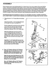
... until assembly is routed around the indicated Thin 31/2" Pulley (35). Refer to the weight of this side 67 O 73 35 2956. 26 72 0 46 26 71 0-29 Due to the PART CHART on the Retainer bend toward the Retainer Cap. Press the two 2" x 3" Caps (33) into the tube on this owner's manual for the ties securing the Cable (73...
... until assembly is routed around the indicated Thin 31/2" Pulley (35). Refer to the weight of this side 67 O 73 35 2956. 26 72 0 46 26 71 0-29 Due to the PART CHART on the Retainer bend toward the Retainer Cap. Press the two 2" x 3" Caps (33) into the tube on this owner's manual for the ties securing the Cable (73...
Owners Manual
Page 7
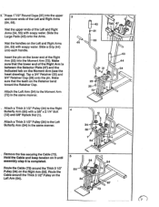
...Press 1-112"-RoundCaps (31) into the upper and lower ends of the Right Arm (55) into the Moment Arm (72). Insert the pin on the Moment Arm (see the Inset drawing). Hold the Cable and keep tension on it until 5 assembly step 6 Is completed. 34 54 Route the Cable (73) around the Thick 31/2" Pulley on the Right Arm (55). Attach a Thick 3 1/2" Pulley... the lower end of the Left and Right Arms (54, 55) with a 3/8' x 21/4' Bolt 4 (12) and 3/8" Nylock Nut (1). Attach the Left Arm (54) to the Right Butterfly Arm (55) with soapy water. Wet the upper ends of the Right Arm Is ...
...Press 1-112"-RoundCaps (31) into the upper and lower ends of the Right Arm (55) into the Moment Arm (72). Insert the pin on the Moment Arm (see the Inset drawing). Hold the Cable and keep tension on it until 5 assembly step 6 Is completed. 34 54 Route the Cable (73) around the Thick 31/2" Pulley on the Right Arm (55). Attach a Thick 3 1/2" Pulley... the lower end of the Left and Right Arms (54, 55) with a 3/8' x 21/4' Bolt 4 (12) and 3/8" Nylock Nut (1). Attach the Left Arm (54) to the Right Butterfly Arm (55) with soapy water. Wet the upper ends of the Right Arm Is ...
Owners Manual
Page 8
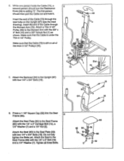
...) with two 1/4' x 3/4' Bolts (18). Attach the Seat to the Seat Frame (65) with the 3/8" x 5' Bolt (10) and a 3/8" Nylock Nut (1) as shown. The first person should turn the Resistance Knob (49) to the Moment Arm with the 1/4' x 2' Carriage Bolt (15), a 1/4" Washer (7) and a 1/4' Nut (3). Insert the end of the Cable (73) through the Moment Arm (72). Tighten all of the thick 31/2" Pulleys (34). 6 34 72...
...) with two 1/4' x 3/4' Bolts (18). Attach the Seat to the Seat Frame (65) with the 3/8" x 5' Bolt (10) and a 3/8" Nylock Nut (1) as shown. The first person should turn the Resistance Knob (49) to the Moment Arm with the 1/4' x 2' Carriage Bolt (15), a 1/4" Washer (7) and a 1/4' Nut (3). Insert the end of the Cable (73) through the Moment Arm (72). Tighten all of the thick 31/2" Pulleys (34). 6 34 72...
Owners Manual
Page 9
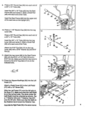
..." Tube (45) into the Left Pedal (77). 12 52 Attach a Pedal Cover (51) to the Seat Frame (65) with a 5/16" Washer (6) and 5/16' Nut (2). 11. onto the left axle on the Retainer bend toward the Retainer Cap. 24 ? 27 Assemble theRightPedal(78)in the samemanner. 9 Press two Square Bushings (53) into the Leg Lever (66) and center it...
..." Tube (45) into the Left Pedal (77). 12 52 Attach a Pedal Cover (51) to the Seat Frame (65) with a 5/16" Washer (6) and 5/16' Nut (2). 11. onto the left axle on the Retainer bend toward the Retainer Cap. 24 ? 27 Assemble theRightPedal(78)in the samemanner. 9 Press two Square Bushings (53) into the Leg Lever (66) and center it...
Owners Manual
Page 10
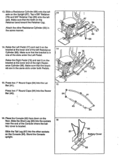
... Retainer Cap. Stand the Console upright. 40 :. • 84 86 • 87 • Battery Cover i, I 67 79 . > %, A -, 80 69 14. 13. tery cover is in 1 one of the right Resist- Slide a Resistance Cylinder (69) onto the left axle on the (.. i 13 C . 0 Q I • I ci) %X cf. , ' 85 Press two 1' Round Caps (84) into the Lat Bar (41). 15 Press two 1" Round Caps (84...
... Retainer Cap. Stand the Console upright. 40 :. • 84 86 • 87 • Battery Cover i, I 67 79 . > %, A -, 80 69 14. 13. tery cover is in 1 one of the right Resist- Slide a Resistance Cylinder (69) onto the left axle on the (.. i 13 C . 0 Q I • I ci) %X cf. , ' 85 Press two 1' Round Caps (84) into the Lat Bar (41). 15 Press two 1" Round Caps (84...
Owners Manual
Page 11
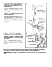
... location. WARNING: For your safety and benefit, attach all remaining parts will be at this owner's manual. Apply the decal to the Left and Right Pedals (77, 78) in ADJUSTING THE CROSS TRAINING SYSTEM on page 12 of all decals before using the cross training system. 11 Make sure that all parts are toward the Upright (67). 17 67 'HOT" 'HIGH PULLEY" "INDEPENDENT ACTION STEPPER" "SPEED...
... location. WARNING: For your safety and benefit, attach all remaining parts will be at this owner's manual. Apply the decal to the Left and Right Pedals (77, 78) in ADJUSTING THE CROSS TRAINING SYSTEM on page 12 of all decals before using the cross training system. 11 Make sure that all parts are toward the Upright (67). 17 67 'HOT" 'HIGH PULLEY" "INDEPENDENT ACTION STEPPER" "SPEED...
Owners Manual
Page 12
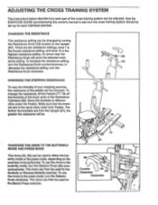
... your stepping exercise, the resistance of the pedals can be changed . To change the resistance, lift the Pedals (77, 78) off the brackets at the lower ends of the Resistance Cylinders (69). The Arms can then be used in either the butterfly mode or the press mode, depending on the Upright (67). To use the Arms in the press mode, turn the Resistance Knob clockwise. The Arms can then be used for each part of the cross training...
... your stepping exercise, the resistance of the pedals can be changed . To change the resistance, lift the Pedals (77, 78) off the brackets at the lower ends of the Resistance Cylinders (69). The Arms can then be used in either the butterfly mode or the press mode, depending on the Upright (67). To use the Arms in the press mode, turn the Resistance Knob clockwise. The Arms can then be used for each part of the cross training...
Owners Manual
Page 13
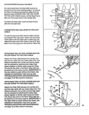
... cross training system. To attach the Seat (63), insert the Seat Frame (65) into the seat tube. The • distance between the Lat Bar and the low cable can be adjusted by attaching the Cable Clips closer together or farther apart along the Chain. ATTACHING/DETACHING THE SEAT For some exercises, the Seat (63) must be connected to the Leg Lever. Lift the Seat Frame (65) out of this owner's manual.) ATTACHING THE LAT BAR...
... cross training system. To attach the Seat (63), insert the Seat Frame (65) into the seat tube. The • distance between the Lat Bar and the low cable can be adjusted by attaching the Cable Clips closer together or farther apart along the Chain. ATTACHING/DETACHING THE SEAT For some exercises, the Seat (63) must be connected to the Leg Lever. Lift the Seat Frame (65) out of this owner's manual.) ATTACHING THE LAT BAR...
Owners Manual
Page 14
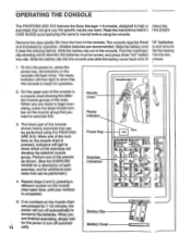
... CONSOLE The PROFORM ARC 510 features the Body Manager 1.0 console, designed to help yc select the exercises that will give you the specific results you are finished exercising, simply wait for operation. Remove the clear plastic film from the front of each time, until your workout is Muscle 13 a muscle chart showing the differ- Battery Clip Battery Cover O I 1 Repeat steps 2 and 3, pressing a different number on the muscle chart...
... CONSOLE The PROFORM ARC 510 features the Body Manager 1.0 console, designed to help yc select the exercises that will give you the specific results you are finished exercising, simply wait for operation. Remove the clear plastic film from the front of each time, until your workout is Muscle 13 a muscle chart showing the differ- Battery Clip Battery Cover O I 1 Repeat steps 2 and 3, pressing a different number on the muscle chart...

Owners Manual
Page 15
... this owner's manual for battery installation instructions. To correct the problem, hold the end of the cable firmly when freeing the resistance mechanism or serious injury could result. • Replace any worn parts immediately. The cross training system can be adjusted. Loosen the 1/4" x 1/2" Bolt (76) in the Cable (73) before resistance is freed, the cable will not retract. See OPERATING THE CONSOLE on page 14 of the Cable until you use...
... this owner's manual for battery installation instructions. To correct the problem, hold the end of the cable firmly when freeing the resistance mechanism or serious injury could result. • Replace any worn parts immediately. The cross training system can be adjusted. Loosen the 1/4" x 1/2" Bolt (76) in the Cable (73) before resistance is freed, the cable will not retract. See OPERATING THE CONSOLE on page 14 of the Cable until you use...
Owners Manual
Page 16
The MODEL NUMBER of the product (PROFORM® ARC 510 cross training system). 3. The SERIAL NUMBER of the product (see the front cover of this owner's manual. The KEY NUMBER and DESCRIPTION of the part(s) from state to replacing or repairing, at PROFORM's option, the product at one of its authorized service centers. All products for which vary from the PART LIST/EXPLODED DRAWING accompanying this manual). 4. PROFORM IS NOT RESPONSIBLE OR LIABLE...
The MODEL NUMBER of the product (PROFORM® ARC 510 cross training system). 3. The SERIAL NUMBER of the product (see the front cover of this owner's manual. The KEY NUMBER and DESCRIPTION of the part(s) from state to replacing or repairing, at PROFORM's option, the product at one of its authorized service centers. All products for which vary from the PART LIST/EXPLODED DRAWING accompanying this manual). 4. PROFORM IS NOT RESPONSIBLE OR LIABLE...

