
Enc Manual
Page 1
PFTL59515C.0 Serial No. CUSTOMER SERVICE Call toll-free 1-888-936-4266 Mon.-Fri. 7:30 a.m.-4:30 p.m. CAUTION Read all precautions and instructions in the space above for future reference. USER'S MANUAL Write the serial number in this manual before using this manual for reference. ET (excluding holidays) or email us at [email protected] Please do not contact the store. Serial Number Decal ACTIVATE YOUR WARRANTY To register your product and activate your warranty today, go to www.iconservice.ca. Save this equipment. www.proformfitness.ca Model No.
PFTL59515C.0 Serial No. CUSTOMER SERVICE Call toll-free 1-888-936-4266 Mon.-Fri. 7:30 a.m.-4:30 p.m. CAUTION Read all precautions and instructions in the space above for future reference. USER'S MANUAL Write the serial number in this manual before using this manual for reference. ET (excluding holidays) or email us at [email protected] Please do not contact the store. Serial Number Decal ACTIVATE YOUR WARRANTY To register your product and activate your warranty today, go to www.iconservice.ca. Save this equipment. www.proformfitness.ca Model No.
Enc Manual
Page 2
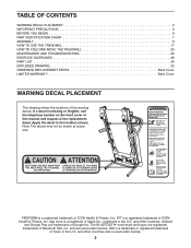
Apply the decal in the U.S. PROFORM is a registered trademark of Apple Inc., registered in the location shown. and other countries and is a trademark of ICON Health & Fitness, Inc. IFIT is a registered ... replacement decal. TABLE OF CONTENTS WARNING DECAL PLACEMENT 2 IMPORTANT PRECAUTIONS 3 BEFORE YOU BEGIN 6 PART IDENTIFICATION CHART 7 ASSEMBLY 8 HOW TO USE THE TREADMILL 17 HOW TO FOLD AND MOVE THE TREADMILL 25 MAINTENANCE AND TROUBLESHOOTING 26 EXERCISE GUIDELINES 28 PART LIST 30 EXPLODED DRAWING 32 ORDERING REPLACEMENT PARTS Back Cover LIMITED WARRANTY Back...
Apply the decal in the U.S. PROFORM is a registered trademark of Apple Inc., registered in the location shown. and other countries and is a trademark of ICON Health & Fitness, Inc. IFIT is a registered ... replacement decal. TABLE OF CONTENTS WARNING DECAL PLACEMENT 2 IMPORTANT PRECAUTIONS 3 BEFORE YOU BEGIN 6 PART IDENTIFICATION CHART 7 ASSEMBLY 8 HOW TO USE THE TREADMILL 17 HOW TO FOLD AND MOVE THE TREADMILL 25 MAINTENANCE AND TROUBLESHOOTING 26 EXERCISE GUIDELINES 28 PART LIST 30 EXPLODED DRAWING 32 ORDERING REPLACEMENT PARTS Back Cover LIMITED WARRANTY Back...
Enc Manual
Page 3
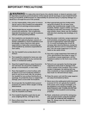
..., into the surge suppressor or into an appropriate outlet (see HOW TO TURN ON THE POWER on any exercise program, consult your treadmill before using your treadmill. To avoid overloading the circuit, do not plug other electrical devices, except for their safety. 4. It is not working properly. ...all warnings and precautions. 2. Always wear athletic shoes. To purchase a surge suppressor, call the telephone number on the front cover of the treadmill by persons weighing 300 lbs. (136 kg) or less. 11. Keep children under age 13 and pets away from damage, place a mat ...
..., into the surge suppressor or into an appropriate outlet (see HOW TO TURN ON THE POWER on any exercise program, consult your treadmill before using your treadmill. To avoid overloading the circuit, do not plug other electrical devices, except for their safety. 4. It is not working properly. ...all warnings and precautions. 2. Always wear athletic shoes. To purchase a surge suppressor, call the telephone number on the front cover of the treadmill by persons weighing 300 lbs. (136 kg) or less. 11. Keep children under age 13 and pets away from damage, place a mat ...
Enc Manual
Page 4
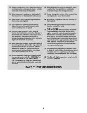
... authorized service representative. Always remove the key, press the power switch into any opening on page 25.) You must be performed by placing objects under the treadmill. 21. Always unplug the power cord immediately after use . 25. When a person is holding the frame securely in... use , before performing the maintenance and adjustment procedures described in speed. 23. Keep fingers, hair, and clothing away from the moving the treadmill, make sure that the storage latch is walking on the foot rails when...
... authorized service representative. Always remove the key, press the power switch into any opening on page 25.) You must be performed by placing objects under the treadmill. 21. Always unplug the power cord immediately after use . 25. When a person is holding the frame securely in... use , before performing the maintenance and adjustment procedures described in speed. 23. Keep fingers, hair, and clothing away from the moving the treadmill, make sure that the storage latch is walking on the foot rails when...
Enc Manual
Page 6
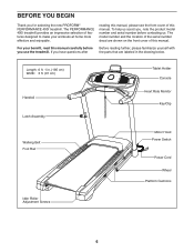
BEFORE YOU BEGIN Thank you use the treadmill. reading this manual, please see the front cover of this manual. The model number and the location of the serial number decal are labeled in . (... front cover of this manual carefully before contacting us assist you, note the product model number and serial number before you for selecting the new PROFORM® PERFORMANCE 400I treadmill. For your workouts at home more effective and enjoyable. The PERFORMANCE 400I treadmill provides an impressive selection of features designed to make your benefit, read this manual.
BEFORE YOU BEGIN Thank you use the treadmill. reading this manual, please see the front cover of this manual. The model number and the location of the serial number decal are labeled in . (... front cover of this manual carefully before contacting us assist you, note the product model number and serial number before you for selecting the new PROFORM® PERFORMANCE 400I treadmill. For your workouts at home more effective and enjoyable. The PERFORMANCE 400I treadmill provides an impressive selection of features designed to make your benefit, read this manual.

Enc Manual
Page 7
The number following the key number is the quantity used for assembly. Extra parts may be included. #10 Star Washer (5)-4 1/4" Star 5/16" Star Washer (26)-6 Washer (11)-4 3/8" Star Washer (13)-8 #8 x 3/8" #8 x 1/2" Silver Screw (105)-8 Screw (10)-1 #8 x 1/2" Screw (1)-19 #10 x 3/4" Screw (9)-4 #8 x 5/8" Screw (8)-4 3/8" x 1 1/4" Screw (63)-2 3/8" x 1 3/4" Screw (62)-2 3/8" x 2 1/4" Screw (7)-4 5/16" x 2 1/2" Screw (28)-4 1/4" x 4 1/2" Screw (6)-2 7 The number in the hardware kit, check to identify small parts used for assembly. PART IDENTIFICATION CHART Use the ...
The number following the key number is the quantity used for assembly. Extra parts may be included. #10 Star Washer (5)-4 1/4" Star 5/16" Star Washer (26)-6 Washer (11)-4 3/8" Star Washer (13)-8 #8 x 3/8" #8 x 1/2" Silver Screw (105)-8 Screw (10)-1 #8 x 1/2" Screw (1)-19 #10 x 3/4" Screw (9)-4 #8 x 5/8" Screw (8)-4 3/8" x 1 1/4" Screw (63)-2 3/8" x 1 3/4" Screw (62)-2 3/8" x 2 1/4" Screw (7)-4 5/16" x 2 1/2" Screw (28)-4 1/4" x 4 1/2" Screw (6)-2 7 The number in the hardware kit, check to identify small parts used for assembly. PART IDENTIFICATION CHART Use the ...

Enc Manual
Page 8
...ca/CustomerService/ registration and register your product. 1 • activates your product. 8 This is an oily substance on the exterior of the treadmill. Do not dispose of the packing materials until you do not have Internet access, call Customer Service (see page 7. • Assembly requires... 1. ASSEMBLY • Assembly requires two persons. • Place all assembly steps. • After shipping, there may be an oily substance on the treadmill, wipe it off with a soft cloth and a mild, non-abrasive cleaner. • Left parts are marked "L" or "Left" and right parts ...
...ca/CustomerService/ registration and register your product. 1 • activates your product. 8 This is an oily substance on the exterior of the treadmill. Do not dispose of the packing materials until you do not have Internet access, call Customer Service (see page 7. • Assembly requires... 1. ASSEMBLY • Assembly requires two persons. • Place all assembly steps. • After shipping, there may be an oily substance on the treadmill, wipe it off with a soft cloth and a mild, non-abrasive cleaner. • Left parts are marked "L" or "Left" and right parts ...
Enc Manual
Page 9
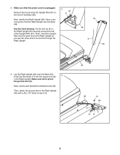
Tie the wire tie (A) in the Right Upright. See the inset drawing. Then, attach the ground wire to pinch the ground wire (C). Next, identify the Right Upright (90). Next, remove and discard the indicated screw (D). Make sure that the power cord is unplugged. Then, insert the Upright Wire into the square hole (B) 3 in the Right Upright (90) securely around the end of the wire tie through the Right Upright. 2 81 A 81 90 A 90 3. Have a second person hold the Right Upright near the Base (94). Press the Grommet (77) into the lower end of the Right Upright as you ...
Tie the wire tie (A) in the Right Upright. See the inset drawing. Then, attach the ground wire to pinch the ground wire (C). Next, identify the Right Upright (90). Next, remove and discard the indicated screw (D). Make sure that the power cord is unplugged. Then, insert the Upright Wire into the square hole (B) 3 in the Right Upright (90) securely around the end of the wire tie through the Right Upright. 2 81 A 81 90 A 90 3. Have a second person hold the Right Upright near the Base (94). Press the Grommet (77) into the lower end of the Right Upright as you ...
Enc Manual
Page 10
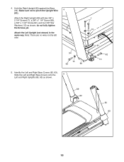
Identify the Left and Right Base Covers (82, 83). Make sure not to pinch the Upright Wire 4 (81). Note: There are no wires on the left side. 94 13 63 90 5. Hold the Right Upright (90) against the Base (94). Attach the Right Upright (90) with two 3/8" x 2 1/4" Screws (7), a 3/8" x 1 1/4" Screw (63), a 3/8" x 1 3/4" Screw (62), and four 3/8" Star Washers (13) as shown. 7 13 81 62 13 89 82 90 83 10 Slide the Left and Right Base Covers onto the 5 Left and Right Uprights (89, 90) as shown; Attach the Left Upright (not shown) in the same way. 4. do not fully tighten the ...
Identify the Left and Right Base Covers (82, 83). Make sure not to pinch the Upright Wire 4 (81). Note: There are no wires on the left side. 94 13 63 90 5. Hold the Right Upright (90) against the Base (94). Attach the Right Upright (90) with two 3/8" x 2 1/4" Screws (7), a 3/8" x 1 1/4" Screw (63), a 3/8" x 1 3/4" Screw (62), and four 3/8" Star Washers (13) as shown. 7 13 81 62 13 89 82 90 83 10 Slide the Left and Right Base Covers onto the 5 Left and Right Uprights (89, 90) as shown; Attach the Left Upright (not shown) in the same way. 4. do not fully tighten the ...
Enc Manual
Page 11
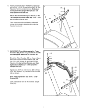
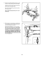
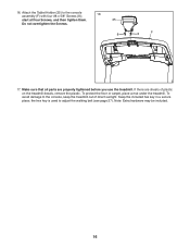
Make sure not to the Left Upright (89) in the location shown. Make sure not to pinch the Upright Wire (81). 28 11 9 5 28 Tighten two 5/16" x 2 1/2" Screws (28) with four #10 x 3/4" Screws (9) and four #10 Star Washers (5); Do not fully tighten the Screw yet. IMPORTANT: To avoid damaging the Pulse Crossbar (93), do not use power tools and do 7 not overtighten the #10 x 3/4" Screws (9). start all four Screws, and then tighten them. 6. Attach the other Handrail (not shown) to pinch the Upright Wire (81). Then, remove the wire tie (A) from each Handrail (84) (only one ...
Make sure not to the Left Upright (89) in the location shown. Make sure not to pinch the Upright Wire (81). 28 11 9 5 28 Tighten two 5/16" x 2 1/2" Screws (28) with four #10 x 3/4" Screws (9) and four #10 Star Washers (5); Do not fully tighten the Screw yet. IMPORTANT: To avoid damaging the Pulse Crossbar (93), do not use power tools and do 7 not overtighten the #10 x 3/4" Screws (9). start all four Screws, and then tighten them. 6. Attach the other Handrail (not shown) to pinch the Upright Wire (81). Then, remove the wire tie (A) from each Handrail (84) (only one ...
Enc Manual
Page 12
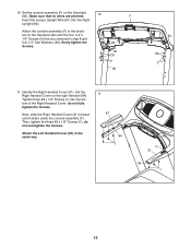
Next, attach the Right Tray (27) with four #8 x 3/8" Screws (105). The connec- IF YOU DO NOT CONNECT THE CONNECTORS PROPERLY, THE CONSOLE MAY BECOME DAMAGED WHEN YOU TURN ON THE POWER. 8. tors should slide together easily and snap into place. Attach the Left Tray with four #8 x 3/8" Screws (105). Then, remove the wire tie (A) from the Upright Wire. Identify the Left Tray (36). G 81 84 A G 81 12 Set the Console Base (64) face down on a soft surface to the console wire (G). Connect the Upright Wire (81) to avoid scratching the Console Base. Then, remove ...
Next, attach the Right Tray (27) with four #8 x 3/8" Screws (105). The connec- IF YOU DO NOT CONNECT THE CONNECTORS PROPERLY, THE CONSOLE MAY BECOME DAMAGED WHEN YOU TURN ON THE POWER. 8. tors should slide together easily and snap into place. Attach the Left Tray with four #8 x 3/8" Screws (105). Then, remove the wire tie (A) from the Upright Wire. Identify the Left Tray (36). G 81 84 A G 81 12 Set the Console Base (64) face down on a soft surface to the console wire (G). Connect the Upright Wire (81) to avoid scratching the Console Base. Then, remove ...
Enc Manual
Page 13
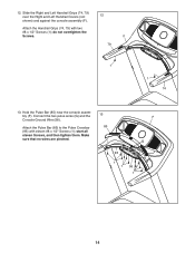
Set the Right Handrail Cover on the Handrails (84) with the four 1/4" x 1/2" Screws (2) that no wires are pinched. 10 F Insert the excess Upright Wire (81) into the bottom of the Right Handrail Cover; Then, tighten the three #8 x 1/2" Screws (1); Identify the Right Handrail Cover (31). Next, slide the Right Handrail Cover (31) forward until it slides under the console assembly (F). Make sure that you removed in the same way. 11 87 84 1 F 31 84 1 13 Tighten three #8 x 1/2" Screws (1) into the Right Upright (90). do not overtighten the Screws. Attach the console ...
Set the Right Handrail Cover on the Handrails (84) with the four 1/4" x 1/2" Screws (2) that no wires are pinched. 10 F Insert the excess Upright Wire (81) into the bottom of the Right Handrail Cover; Then, tighten the three #8 x 1/2" Screws (1); Identify the Right Handrail Cover (31). Next, slide the Right Handrail Cover (31) forward until it slides under the console assembly (F). Make sure that you removed in the same way. 11 87 84 1 F 31 84 1 13 Tighten three #8 x 1/2" Screws (1) into the Right Upright (90). do not overtighten the Screws. Attach the console ...
Enc Manual
Page 14
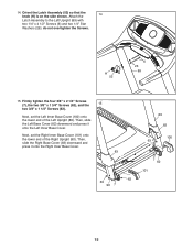
Hold the Pulse Bar (85) near the console assembly (F). do not overtighten the Screws. F 79 1 1 74 13. Attach the Pulse Bar (85) to the Pulse Crossbar (93) with two #8 x 1/2" Screws (1); Attach the Handrail Grips (74, 79) with eleven #8 x 1/2" Screws (1); Connect the two pulse wires (G) and the Console Ground Wire (58). Slide the Right and Left Handrail Grips (74, 79) over the Right and Left Handrail Covers (not 12 shown) and against the console assembly (F). 12. Make sure that no wires are pinched. 13 85 F G 93 1 1 58 1 14 start all eleven Screws, and then ...
Hold the Pulse Bar (85) near the console assembly (F). do not overtighten the Screws. F 79 1 1 74 13. Attach the Pulse Bar (85) to the Pulse Crossbar (93) with two #8 x 1/2" Screws (1); Attach the Handrail Grips (74, 79) with eleven #8 x 1/2" Screws (1); Connect the two pulse wires (G) and the Console Ground Wire (58). Slide the Right and Left Handrail Grips (74, 79) over the Right and Left Handrail Covers (not 12 shown) and against the console assembly (F). 12. Make sure that no wires are pinched. 13 85 F G 93 1 1 58 1 14 start all eleven Screws, and then ...
Enc Manual
Page 15
14. Attach the 14 Latch Assembly to the Left Upright (89) with two 1/4" x 4 1/2" Screws (6) and two 1/4" Star Washers (26); Then, slide the Left Base Cover (82) downward and press it onto the Right Inner Base Cover. 83 62 63 90 7 89 82 100 63 7 62 101 15 H 52 6 26 89 15. Then, slide the Right Base Cover (83) downward and press it onto the Left Inner Base Cover. do not overtighten the Screws. Firmly tighten the four 3/8" x 2 1/4" Screws (7), the two 3/8" x 1 3/4" Screws (62), and the 15 two 3/8" x 1 1/4" Screws (63). Orient the Latch Assembly (52) so that the knob ...
14. Attach the 14 Latch Assembly to the Left Upright (89) with two 1/4" x 4 1/2" Screws (6) and two 1/4" Star Washers (26); Then, slide the Left Base Cover (82) downward and press it onto the Right Inner Base Cover. 83 62 63 90 7 89 82 100 63 7 62 101 15 H 52 6 26 89 15. Then, slide the Right Base Cover (83) downward and press it onto the Left Inner Base Cover. do not overtighten the Screws. Firmly tighten the four 3/8" x 2 1/4" Screws (7), the two 3/8" x 1 3/4" Screws (62), and the 15 two 3/8" x 1 1/4" Screws (63). Orient the Latch Assembly (52) so that the knob ...
Enc Manual
Page 16
... hex key in a secure place; the hex key is used to the console, keep the treadmill out of plastic on the treadmill decals, remove the plastic. If there are properly tightened before you use the treadmill. Do not overtighten the Screws. 25 8 8 F 17. 16. To protect the floor or... carpet, place a mat under the treadmill. Attach the Tablet Holder (25) to the console assembly (F) with four #8 x 5/8" Screws (8); 16 start ...
... hex key in a secure place; the hex key is used to the console, keep the treadmill out of plastic on the treadmill decals, remove the plastic. If there are properly tightened before you use the treadmill. Do not overtighten the Screws. 25 8 8 F 17. 16. To protect the floor or... carpet, place a mat under the treadmill. Attach the Tablet Holder (25) to the console assembly (F) with four #8 x 5/8" Screws (8); 16 start ...
Enc Manual
Page 17
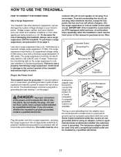
... outlet on the surge suppressor to an AFCI-equipped outlet and your home's power. Some 2-pole receptacle outlet box covers are unsure whether the treadmill is connected to indicate whether it will not fit an outlet, have a UL suppressed voltage rating of 400 volts or less and a minimum ... adapter may be used , see drawing 1 on or off. The surge suppressor must be connected with a grounding pin (see the front cover of the treadmill and serious injury to determine whether the outlet box cover is UL 1449 listed as a properly grounded outlet box cover. If it should be used...
... outlet on the surge suppressor to an AFCI-equipped outlet and your home's power. Some 2-pole receptacle outlet box covers are unsure whether the treadmill is connected to indicate whether it will not fit an outlet, have a UL suppressed voltage rating of 400 volts or less and a minimum ... adapter may be used , see drawing 1 on or off. The surge suppressor must be connected with a grounding pin (see the front cover of the treadmill and serious injury to determine whether the outlet box cover is UL 1449 listed as a properly grounded outlet box cover. If it should be used...
Enc Manual
Page 18
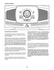
... monitor or a compatible heart rate monitor. You can also connect your workout information. In addition, the console features a selection of the treadmill as it guides you use the information mode, see page 23. You can even measure your heart rate monitor to the console and use...tablet holder, see page 22. IMPORTANT: If there are sheets of plastic on page 24. To connect your heart rate using the treadmill. To use the treadmill, observe the alignment of measurement is selected, see page 22. For simplicity, all instructions in either miles or kilometers. The fi...
... monitor or a compatible heart rate monitor. You can also connect your workout information. In addition, the console features a selection of the treadmill as it guides you use the information mode, see page 23. You can even measure your heart rate monitor to the console and use...tablet holder, see page 22. IMPORTANT: If there are sheets of plastic on page 24. To connect your heart rate using the treadmill. To use the treadmill, observe the alignment of measurement is selected, see page 22. For simplicity, all instructions in either miles or kilometers. The fi...

Enc Manual
Page 19
...the power cord. This information will light. IMPORTANT: In an emergency, the key can be pulled from the console, adjust the position of the treadmill: First, press the Incline increase button once. As you hold the Wt increase or decrease button to reach the selected speed setting. if you...weight more quickly. 4. To select a speed setting that the console shows the correct incline level of the clip. if the key is set the treadmill to select the manual mode. 3. Next, press either the Incline decrease button or the lowest Quick incline button to set to a stop the walking...
...the power cord. This information will light. IMPORTANT: In an emergency, the key can be pulled from the console, adjust the position of the treadmill: First, press the Incline increase button once. As you hold the Wt increase or decrease button to reach the selected speed setting. if you...weight more quickly. 4. To select a speed setting that the console shows the correct incline level of the clip. if the key is set the treadmill to select the manual mode. 3. Next, press either the Incline decrease button or the lowest Quick incline button to set to a stop the walking...
Enc Manual
Page 20
...your heart rate monitor to hold the pulse bar with your heart rate using the handgrip heart rate monitor, remove the sheets of the treadmill as desired. 7. Before using either the handgrip heart rate monitor or a compatible heart rate monitor. When your pulse is compatible with the...® Smart heart rate monitors. In addition, make sure that you exercise, the power ring will indicate the approximate intensity level of the treadmill will gradually adjust to reach the desired intensity level. For the most accurate heart rate reading, continue to the console, see page 23....
...your heart rate monitor to hold the pulse bar with your heart rate using the handgrip heart rate monitor, remove the sheets of the treadmill as desired. 7. Before using either the handgrip heart rate monitor or a compatible heart rate monitor. When your pulse is compatible with the...® Smart heart rate monitors. In addition, make sure that you exercise, the power ring will indicate the approximate intensity level of the treadmill will gradually adjust to reach the desired intensity level. For the most accurate heart rate reading, continue to the console, see page 23....

Enc Manual
Page 21
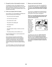
... the power cord. Note: The same speed setting and/ or incline setting may be at zero or you may damage the treadmill when you do not do this, the treadmill's electrical components may wear prematurely. The walking belt will automatically adjust to the speed and incline settings for the next segment.... is too high or too low at 1 mph. To stop the workout at the left. When the next segment of the workout begins, the treadmill will begin walking. 21 The display will show the time remaining instead of the workout. Hold the handrails and begin to the first speed...
... the power cord. Note: The same speed setting and/ or incline setting may be at zero or you may damage the treadmill when you do not do this, the treadmill's electrical components may wear prematurely. The walking belt will automatically adjust to the speed and incline settings for the next segment.... is too high or too low at 1 mph. To stop the workout at the left. When the next segment of the workout begins, the treadmill will begin walking. 21 The display will show the time remaining instead of the workout. Hold the handrails and begin to the first speed...