
English Manual
Page 2
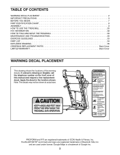
... Google Maps is missing or illegible, call the telephone number on the front cover of this manual and request a free replacement decal. PROFORM and IFIT are used under license. and are registered trademarks of Google Inc. 2 If a decal is a trademark of ICON Health &... WARNING DECAL PLACEMENT 2 IMPORTANT PRECAUTIONS 3 BEFORE YOU BEGIN 7 PART IDENTIFICATION CHART 8 ASSEMBLY 9 HOW TO USE THE TREADMILL 20 FCC INFORMATION 28 HOW TO FOLD AND MOVE THE TREADMILL 29 MAINTENANCE AND TROUBLESHOOTING 30 EXERCISE GUIDELINES 33 PART LIST 34 EXPLODED DRAWING 36 ORDERING REPLACEMENT...
... Google Maps is missing or illegible, call the telephone number on the front cover of this manual and request a free replacement decal. PROFORM and IFIT are used under license. and are registered trademarks of Google Inc. 2 If a decal is a trademark of ICON Health &... WARNING DECAL PLACEMENT 2 IMPORTANT PRECAUTIONS 3 BEFORE YOU BEGIN 7 PART IDENTIFICATION CHART 8 ASSEMBLY 9 HOW TO USE THE TREADMILL 20 FCC INFORMATION 28 HOW TO FOLD AND MOVE THE TREADMILL 29 MAINTENANCE AND TROUBLESHOOTING 30 EXERCISE GUIDELINES 33 PART LIST 34 EXPLODED DRAWING 36 ORDERING REPLACEMENT...
English Manual
Page 4
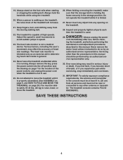
...speed. 23. ing the treadmill, and before clean- If you feel faint, if you become short of heart rate readings. Do not operate the treadmill while it is not in . (20 cm) from the moving the treadmill, make sure that the storage latch is properly assembled. (See ASSEMBLY on page 9, and ...HOW TO FOLD AND MOVE THE TREADMILL on the foot rails when starting or stopping the...
...speed. 23. ing the treadmill, and before clean- If you feel faint, if you become short of heart rate readings. Do not operate the treadmill while it is not in . (20 cm) from the moving the treadmill, make sure that the storage latch is properly assembled. (See ASSEMBLY on page 9, and ...HOW TO FOLD AND MOVE THE TREADMILL on the foot rails when starting or stopping the...
English Manual
Page 8
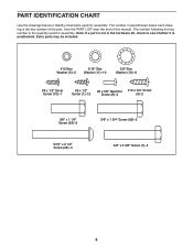
The number following the key number is the quantity used for assembly. Note: If a part is not in parentheses below to see whether it is preattached. PART IDENTIFICATION CHART Use the drawings below each drawing is the ... #8 x 5/8" Machine #10 x 3/4" Screw Screw (8)-4 (9)-2 3/8" x 1 1/4" Screw (63)-2 5/16" x 2 1/2" Screw (28)-4 3/8" x 1 3/4" Screw (62)-2 3/8" x 2 3/8" Screw (7)-4 8 The number in the hardware kit, check to identify small parts used for assembly.
The number following the key number is the quantity used for assembly. Note: If a part is not in parentheses below to see whether it is preattached. PART IDENTIFICATION CHART Use the drawings below each drawing is the ... #8 x 5/8" Machine #10 x 3/4" Screw Screw (8)-4 (9)-2 3/8" x 1 1/4" Screw (63)-2 5/16" x 2 1/2" Screw (28)-4 3/8" x 1 3/4" Screw (62)-2 3/8" x 2 3/8" Screw (7)-4 8 The number in the hardware kit, check to identify small parts used for assembly.
English Manual
Page 9
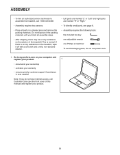
Go to assemble the treadmill, call 1-800-445-2480 • Assembly requires two persons. • Place all assembly steps. • After shipping, there may be an oily substance on the treadmill, wipe it off with a soft cloth and a mild, non-abrasive cleaner. • Left parts are marked "L"...cover of this manual) and register your warranty • ensures priority customer support if assistance is normal. ASSEMBLY • To hire an authorized service technician to my.proform.com on your computer and register your product. 1 • documents your ownership • activates your...
Go to assemble the treadmill, call 1-800-445-2480 • Assembly requires two persons. • Place all assembly steps. • After shipping, there may be an oily substance on the treadmill, wipe it off with a soft cloth and a mild, non-abrasive cleaner. • Left parts are marked "L"...cover of this manual) and register your warranty • ensures priority customer support if assistance is normal. ASSEMBLY • To hire an authorized service technician to my.proform.com on your computer and register your product. 1 • documents your ownership • activates your...
English Manual
Page 12
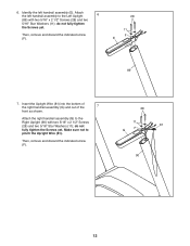
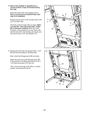
Insert the Upright Wire (81) into the bottom of the right handrail assembly (G) and out of the 7 front as shown. Attach the left handrail assembly (E). do not fully tighten the Screws yet. do not fully tighten the Screws yet. Make sure not to the Right Upright (90) with two 5/16" ...x 2 1/2" Screws (28) and two 5/16" Star Washers (11); Then, remove and discard the indicated screw (F). 28 11 F E 89 7. Identify the left handrail assembly to the Left Upright 6 (89) with two 5/16" x 2 1/2" Screws (28) and two 5/16" Star Washers (11); Attach the right handrail...
Insert the Upright Wire (81) into the bottom of the right handrail assembly (G) and out of the 7 front as shown. Attach the left handrail assembly (E). do not fully tighten the Screws yet. do not fully tighten the Screws yet. Make sure not to the Right Upright (90) with two 5/16" ...x 2 1/2" Screws (28) and two 5/16" Star Washers (11); Then, remove and discard the indicated screw (F). 28 11 F E 89 7. Identify the left handrail assembly to the Left Upright 6 (89) with two 5/16" x 2 1/2" Screws (28) and two 5/16" Star Washers (11); Attach the right handrail...
English Manual
Page 14
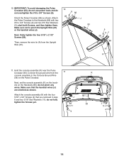
.... 93 Make sure not to the Handrails (86) with the four 5/16" x 3/4" Screws (4) that the handrail wires (J) are oriented as shown. Hold the console assembly (K) near the Pulse Crossbar (93). do not fully tighten the Screws yet. 11 J 86 11 4 K 58 93 86 J 11 4 14 Next, firmly tighten...#10 x 3/4" Screws (9) and two #10 Star Washers (5); Then, remove the wire tie (A) from the console assembly to the Console Ground Wire (58) on the Handrails (86); Next, set the console assembly (K) on the brackets on the Pulse Crossbar. Attach J the Pulse Crossbar to pinch the Upright Wire (81) or...
.... 93 Make sure not to the Handrails (86) with the four 5/16" x 3/4" Screws (4) that the handrail wires (J) are oriented as shown. Hold the console assembly (K) near the Pulse Crossbar (93). do not fully tighten the Screws yet. 11 J 86 11 4 K 58 93 86 J 11 4 14 Next, firmly tighten...#10 x 3/4" Screws (9) and two #10 Star Washers (5); Then, remove the wire tie (A) from the console assembly to the Console Ground Wire (58) on the Handrails (86); Next, set the console assembly (K) on the brackets on the Pulse Crossbar. Attach J the Pulse Crossbar to pinch the Upright Wire (81) or...
English Manual
Page 15
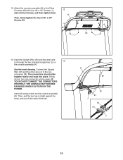
Attach the console assembly (K) to the console wires (M). If they do not, turn one connector and try again. IF YOU DO NOT CONNECT ...firmly tighten the four 5/16" x 3/4" Screws (4). 12 K 4 1 4 93 1 13. The connectors should slide together easily and snap into the console assembly (K). Insert all four Screws, and then tighten them. Then, pull the two ties (L) tight against the wires, and cut off the ends of the ties.... Connect the Upright Wire (81) and the other wire (J) through the two indicated looped ties (L) on 13 the console assembly (K). K L M 81 J M 81 J 15 12.
Attach the console assembly (K) to the console wires (M). If they do not, turn one connector and try again. IF YOU DO NOT CONNECT ...firmly tighten the four 5/16" x 3/4" Screws (4). 12 K 4 1 4 93 1 13. The connectors should slide together easily and snap into the console assembly (K). Insert all four Screws, and then tighten them. Then, pull the two ties (L) tight against the wires, and cut off the ends of the ties.... Connect the Upright Wire (81) and the other wire (J) through the two indicated looped ties (L) on 13 the console assembly (K). K L M 81 J M 81 J 15 12.
English Manual
Page 16
... ties (L) on the console assem- 14 bly (K), and then connect the wire to the wire on the console. Insert all excess wires into the console assembly (K). the Wheels (103) must turn freely. Then, set the Left Inner Base Cover (100) onto the lower end of the Left Upright (89). Slide the...
... ties (L) on the console assem- 14 bly (K), and then connect the wire to the wire on the console. Insert all excess wires into the console assembly (K). the Wheels (103) must turn freely. Then, set the Left Inner Base Cover (100) onto the lower end of the Left Upright (89). Slide the...
English Manual
Page 17
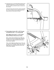
... Next, orient the Storage Latch (53) as shown. O N 38 O 11 4 11 4 56 17. Have a second person hold the Frame until step 18 is facing the treadmill. Remove the 5/16" Nut (12) and the 5/16" x 1 3/4" Bolt (6) from the Latch Crossbar (38). Remove the two 5/16" x 3/4" Screws (4) from the bracket... Then, raise the Storage Latch (53) to the bracket on a smooth surface, it may roll forward during 16 this step. Note: If the treadmill is assembled on the Base (94) with the two 5/16" x 3/4" Screws (4) that the "This side toward belt" sticker (N) is completed. 16.
... Next, orient the Storage Latch (53) as shown. O N 38 O 11 4 11 4 56 17. Have a second person hold the Frame until step 18 is facing the treadmill. Remove the 5/16" Nut (12) and the 5/16" x 1 3/4" Bolt (6) from the Latch Crossbar (38). Remove the two 5/16" x 3/4" Screws (4) from the bracket... Then, raise the Storage Latch (53) to the bracket on a smooth surface, it may roll forward during 16 this step. Note: If the treadmill is assembled on the Base (94) with the two 5/16" x 3/4" Screws (4) that the "This side toward belt" sticker (N) is completed. 16.
English Manual
Page 18
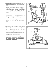
..." x 2 1/4" Bolt (3); the Storage Latch (53) must be able to overtighten the Machine Screws. Then, lower the Frame (56) (see HOW TO LOWER THE TREADMILL FOR USE on the Latch Crossbar (38). Be careful not to pivot. do not overtighten the Nut; Align the upper end of the other electronic... device or object in the console assembly (K). Press the two tabs on the Latch Crossbar (38), and insert the 5/16" x 2 1/4" Bolt (3) through the bracket and the Storage Latch. IMPORTANT: ...
..." x 2 1/4" Bolt (3); the Storage Latch (53) must be able to overtighten the Machine Screws. Then, lower the Frame (56) (see HOW TO LOWER THE TREADMILL FOR USE on the Latch Crossbar (38). Be careful not to pivot. do not overtighten the Nut; Align the upper end of the other electronic... device or object in the console assembly (K). Press the two tabs on the Latch Crossbar (38), and insert the 5/16" x 2 1/4" Bolt (3) through the bracket and the Storage Latch. IMPORTANT: ...
English Manual
Page 21
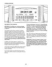
... remove the plastic. To use the iFit® Bluetooth Tablet app to the console and use the sound system, see page 26. The treadmill console offers a selection of measurement is selected, see THE SETTINGS MODE on page 19. See page 26 for information about purchasing an optional ... and track your workout information. CONSOLE DIAGRAM FEATURES OF THE CONSOLE IMPORTANT: To activate your console and begin using its exclusive features, see assembly step 20 on page 27. As you through an effective exercise session. To connect your workouts more effective and enjoyable. To find...
... remove the plastic. To use the iFit® Bluetooth Tablet app to the console and use the sound system, see page 26. The treadmill console offers a selection of measurement is selected, see THE SETTINGS MODE on page 19. See page 26 for information about purchasing an optional ... and track your workout information. CONSOLE DIAGRAM FEATURES OF THE CONSOLE IMPORTANT: To activate your console and begin using its exclusive features, see assembly step 20 on page 27. As you through an effective exercise session. To connect your workouts more effective and enjoyable. To find...

English Manual
Page 30
...the power cord is plugged into a surge suppressor, and that the key is plugged into the off during use a. c. Check the power switch (see assembly step 20 on . Remove the key from the console. d. After the power cord has been plugged in a store. If the switch protrudes as shown...switch has tripped. Replace any worn parts immediately. If further assistance is turned on page 19. IMPORTANT: Do not spray liquids directly onto the treadmill. If you have not activated the console, see the drawing above). SYMPTOM: The console displays remain lit when you remove the key, the demo...
...the power cord is plugged into a surge suppressor, and that the key is plugged into the off during use a. c. Check the power switch (see assembly step 20 on . Remove the key from the console. d. After the power cord has been plugged in a store. If the switch protrudes as shown...switch has tripped. Replace any worn parts immediately. If further assistance is turned on page 19. IMPORTANT: Do not spray liquids directly onto the treadmill. If you have not activated the console, see the drawing above). SYMPTOM: The console displays remain lit when you remove the key, the demo...


