
Instruction Manual
Page 2
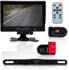
... are noserviceable parts in the video camera system setup.See the wiring diagram for reverse and parking. Upon Installation, please make sure as to not to interfere with one super slim license plate backup camera. If the unit malfunctions please return to yourvendor or send to insert the TF card( we suggest use . PLCMDVR72 INTRODUCTION This model is for connections between cameras, monitor and your safety, the driver should be...
... are noserviceable parts in the video camera system setup.See the wiring diagram for reverse and parking. Upon Installation, please make sure as to not to interfere with one super slim license plate backup camera. If the unit malfunctions please return to yourvendor or send to insert the TF card( we suggest use . PLCMDVR72 INTRODUCTION This model is for connections between cameras, monitor and your safety, the driver should be...
Instruction Manual
Page 3
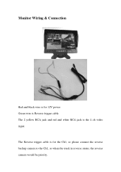
The Reverse trigger cable is the 4 ch video input. Monitor Wiring & Connection Red and black wire is for 12V power Green wire is Reverse trigger cable The 2 yellow RCA jack and red and white RCA jack is for the Ch1, so please connect the reverse backup camera to the Ch1, so when the truck in reverse status, the reverse camera would be priority.
The Reverse trigger cable is the 4 ch video input. Monitor Wiring & Connection Red and black wire is for 12V power Green wire is Reverse trigger cable The 2 yellow RCA jack and red and white RCA jack is for the Ch1, so please connect the reverse backup camera to the Ch1, so when the truck in reverse status, the reverse camera would be priority.
Instruction Manual
Page 4
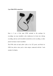
2 pcs Mini DVR connection there is 2 pcs of this mini DVR included in the package for recording( one may installed at the windscreen for front view driving recording, and one can be installed at inside the car for recording ,or other placed customers want to installed) The DVR cable red and yellow cable is for 12V power, and black for GND, the yellow video jack is video output, connected with the 7 inch monitor for display.
2 pcs Mini DVR connection there is 2 pcs of this mini DVR included in the package for recording( one may installed at the windscreen for front view driving recording, and one can be installed at inside the car for recording ,or other placed customers want to installed) The DVR cable red and yellow cable is for 12V power, and black for GND, the yellow video jack is video output, connected with the 7 inch monitor for display.
Instruction Manual
Page 5
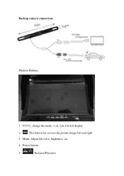
V1/V2: change the mode, 1 ch, 2ch,3ch,4ch display 2. Power button 5. Menu: Adjust the color, brightness, etc. 4. Increase/Decrease Backup camera connection: Monitor Buttons: 1. This button for reverse the picture image left and right 3.
V1/V2: change the mode, 1 ch, 2ch,3ch,4ch display 2. Power button 5. Menu: Adjust the color, brightness, etc. 4. Increase/Decrease Backup camera connection: Monitor Buttons: 1. This button for reverse the picture image left and right 3.
Instruction Manual
Page 6
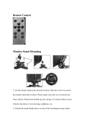
Set the mount stand in the desired location, then use screws to secure the mount stand into location. Please make sure asto set a location free from vehicle obstruction include ng any wiring, or location where it may obstruct the driver's view,driving conditions, etc. 2. Attach the metal buckle piece on top of the fan shaped mount stand, Remote Control Monitor Stand Mounting 1.
Set the mount stand in the desired location, then use screws to secure the mount stand into location. Please make sure asto set a location free from vehicle obstruction include ng any wiring, or location where it may obstruct the driver's view,driving conditions, etc. 2. Attach the metal buckle piece on top of the fan shaped mount stand, Remote Control Monitor Stand Mounting 1.

Instruction Manual
Page 7
Set the desired position/height of the stand mount to the monitor assembly. 3. The angle / tilt position of the stand mount is another clamp‐style knob. This metal buckle should slide in and up to secure the monitor in the desired position. 5. Tighten the clamp‐style knob in the back of the buckle into the receiving slot in back of the stand mount is also adjustable. and slide it into the monitor assembly. 4. Located toward the base of thedisplay monitor assembly.
Set the desired position/height of the stand mount to the monitor assembly. 3. The angle / tilt position of the stand mount is another clamp‐style knob. This metal buckle should slide in and up to secure the monitor in the desired position. 5. Tighten the clamp‐style knob in the back of the buckle into the receiving slot in back of the stand mount is also adjustable. and slide it into the monitor assembly. 4. Located toward the base of thedisplay monitor assembly.


