
Instruction Manual
Page 2
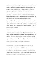
... wiring diagram for all cameras. We are colored wires to your safety, the driver should be performed by a professional installer. Use the included wiring harness to provide power and video signals to your vendor or send to your monitor. Connection Connect the camera's threaded locking 4‐pin cable connectors into the female receiving connection of the camera serve to faulty or non‐professional installation. If the unit malfunctions please return to a Pyle repair facility. To ensure your compatible video monitors...
... wiring diagram for all cameras. We are colored wires to your safety, the driver should be performed by a professional installer. Use the included wiring harness to provide power and video signals to your vendor or send to your monitor. Connection Connect the camera's threaded locking 4‐pin cable connectors into the female receiving connection of the camera serve to faulty or non‐professional installation. If the unit malfunctions please return to a Pyle repair facility. To ensure your compatible video monitors...
Instruction Manual
Page 3
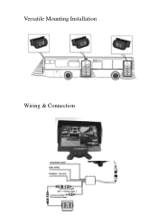
Versatile Mounting Installation Wiring & Connection
Versatile Mounting Installation Wiring & Connection
Instruction Manual
Page 4
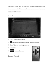
This button for the Ch1, so please connect the reverse backup camera to the Ch1, so when the truck in reverse status, the reverse camera would be priority. The Reverse trigger cable is for reverse the picture image left and right 3. Increase/Decrease Remote Control Menu: Adjust the color, brightness, etc. 4. Monitor Buttons: 1. Power button 5. V1/V2: Switch the ch1 and ch2 2.
This button for the Ch1, so please connect the reverse backup camera to the Ch1, so when the truck in reverse status, the reverse camera would be priority. The Reverse trigger cable is for reverse the picture image left and right 3. Increase/Decrease Remote Control Menu: Adjust the color, brightness, etc. 4. Monitor Buttons: 1. Power button 5. V1/V2: Switch the ch1 and ch2 2.

Instruction Manual
Page 5
... secure the monitor in the desired location, then use screws to the monitor assembly. 3. Tighten the clamp‐style knob in back of the stand mount to set a location free from vehicle obstruction including any wiring, or location where it into the monitor assembly. 4. Set the desired position/height of the buckle into the receiving slot in the back of the display monitor assembly.
... secure the monitor in the desired location, then use screws to the monitor assembly. 3. Tighten the clamp‐style knob in back of the stand mount to set a location free from vehicle obstruction including any wiring, or location where it into the monitor assembly. 4. Set the desired position/height of the buckle into the receiving slot in the back of the display monitor assembly.

