PLMRKT14BK Manual 1
Page 2
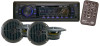
CONTENTS Installation 3 Take out screw before installation......3 DIN Front-Mount (Method A 3 Installing the unit 3 Removing the unit 4 DIN Rear-Mount (Method B 5 Wiring Connection 6 Operation 7 Location of keys 7 Switching on/off the unit 8 Sound adjustment 8 Loudness 8 Display 8 Mute 8 Equalization 8 Remote sensor 8 Reset function 8 Radio operation 8 Switching to radio ...
CONTENTS Installation 3 Take out screw before installation......3 DIN Front-Mount (Method A 3 Installing the unit 3 Removing the unit 4 DIN Rear-Mount (Method B 5 Wiring Connection 6 Operation 7 Location of keys 7 Switching on/off the unit 8 Sound adjustment 8 Loudness 8 Display 8 Mute 8 Equalization 8 Remote sensor 8 Reset function 8 Radio operation 8 Switching to radio ...
PLMRKT14BK Manual 1
Page 3
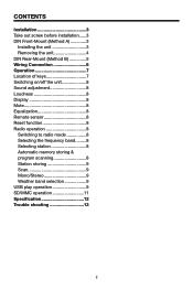
Disconnect the wire harness and the antenna. 3. Press the release button on the front panel and remove the control panel (see the steps of "to the following illustrated ... dashboard having an opening as they will not interfere with the normal driving function of the driver. • Before finally installing the unit, connect the wiring temporarily and make sure it is all connections first, and then follow these steps to install the unit. 1. TAKE OUT SCREW BEFORE INSTALLATION Before install...
Disconnect the wire harness and the antenna. 3. Press the release button on the front panel and remove the control panel (see the steps of "to the following illustrated ... dashboard having an opening as they will not interfere with the normal driving function of the driver. • Before finally installing the unit, connect the wiring temporarily and make sure it is all connections first, and then follow these steps to install the unit. 1. TAKE OUT SCREW BEFORE INSTALLATION Before install...
PLMRKT14BK Manual 1
Page 4
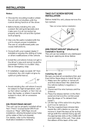
... (M5mm) and Spring 3. Mount the sleeve by inserting the sleeve into place. 9. Remove the metal strap attached the back of "to pinch any wires or cables. 8. Reconnect the wire harness and the antenna and be most effective. Slide the unit into the slots at the middle left and right sides of the...
... (M5mm) and Spring 3. Mount the sleeve by inserting the sleeve into place. 9. Remove the metal strap attached the back of "to pinch any wires or cables. 8. Reconnect the wire harness and the antenna and be most effective. Slide the unit into the slots at the middle left and right sides of the...
PLMRKT14BK Manual 1
Page 6
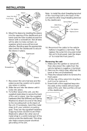
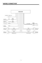
WIRING CONNECTION MAIN UNIT ANTENNA CONNECTOR IGNITION RED SWITCH (ACC+) MEMORY BACK-UP (B+) GROUND (B-) YELLOW BLACK FUSE FUSE POWER ANTENNA FRONT Lch SPEAKER REAR Lch SPEAKER BLUE WHITE WHITE/BLACK GREEN GREEN/BLACK RCA CABLE (GREY) Rch RED Lch WHITE GREY GREY/BLACK VIOLET VIOLET/BLACK FRONT Rch SPEAKER REAR Rch SPEAKER 6
WIRING CONNECTION MAIN UNIT ANTENNA CONNECTOR IGNITION RED SWITCH (ACC+) MEMORY BACK-UP (B+) GROUND (B-) YELLOW BLACK FUSE FUSE POWER ANTENNA FRONT Lch SPEAKER REAR Lch SPEAKER BLUE WHITE WHITE/BLACK GREEN GREEN/BLACK RCA CABLE (GREY) Rch RED Lch WHITE GREY GREY/BLACK VIOLET VIOLET/BLACK FRONT Rch SPEAKER REAR Rch SPEAKER 6
PLMRKT14BK Manual 1
Page 8
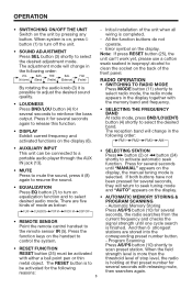
... button (25) must be activated strength level is more than the with either a ball point pen or thin threshold level of the unit when all wiring is holding at that preset number for be connected to a portable audio player through the AUX IN jack (13). • SELECTING STATION Press button (2) or...
... button (25) must be activated strength level is more than the with either a ball point pen or thin threshold level of the unit when all wiring is holding at that preset number for be connected to a portable audio player through the AUX IN jack (13). • SELECTING STATION Press button (2) or...
PLMRKT14BK Manual 1
Page 13
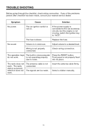
...been made, consult your nearest service dealer. The fuse is not properly connected. Replace the fuse. Adjust volume to noise. Wiring is blown. Check wiring connection. The radio station automatic selection does not work . The antenna cable is not properly fixed due to a desired level.... No sound. into its place. Insert the antenna cable firmly. TROUBLE SHOOTING Before going through the checklist, check wiring connection. The radio does not work. The operation keys The built-in minimum. The signals are too weak. is not operating properly...
...been made, consult your nearest service dealer. The fuse is not properly connected. Replace the fuse. Adjust volume to noise. Wiring is blown. Check wiring connection. The radio station automatic selection does not work . The antenna cable is not properly fixed due to a desired level.... No sound. into its place. Insert the antenna cable firmly. TROUBLE SHOOTING Before going through the checklist, check wiring connection. The radio does not work. The operation keys The built-in minimum. The signals are too weak. is not operating properly...


