
Operation Manual
Page 3
... IMPORTANT INFORMATION INTRODUCTION Overview ix Features ix Options...x Using this Manual x Conventions xi SETTING UP THE SCANNER GENERAL GUIDE 1-1 Front View 1-1 Rear View 1-2 Scanner Indicators 1-2 CHECKING THE PARTS 1-3 SCANNER LOCATION 1-4 CONNECTING TO THE HOST 1-5 To connect to your host 1-5 SETTING THE SCSI ID 1-8... the setting of DIP switch 1 1-9 CONNECTING THE POWER CORD 1-10 To connect the power cord 1-10 TURNING ON THE SCANNER 1-11 To turn on scanner power 1-11 DIP SWITCH SETTINGS 1-12 Switch 1-SCAM Function 1-12 Switch 3-Paper Size 1-12 Switch 4-IS410 Mode 1-12 ...
... IMPORTANT INFORMATION INTRODUCTION Overview ix Features ix Options...x Using this Manual x Conventions xi SETTING UP THE SCANNER GENERAL GUIDE 1-1 Front View 1-1 Rear View 1-2 Scanner Indicators 1-2 CHECKING THE PARTS 1-3 SCANNER LOCATION 1-4 CONNECTING TO THE HOST 1-5 To connect to your host 1-5 SETTING THE SCSI ID 1-8... the setting of DIP switch 1 1-9 CONNECTING THE POWER CORD 1-10 To connect the power cord 1-10 TURNING ON THE SCANNER 1-11 To turn on scanner power 1-11 DIP SWITCH SETTINGS 1-12 Switch 1-SCAM Function 1-12 Switch 3-Paper Size 1-12 Switch 4-IS410 Mode 1-12 ...

Operation Manual
Page 4
... Glass, Slit Glass,White Sheet,White Bar 3-2 Rollers and Belt 3-3 REPLACING THE ROLLER SET 3-5 TROUBLESHOOTING OVERVIEW 4-1 Scanner Problems and Solutions 4-1 Document Feeder Cover Open 4-1 Document Feeder Raised 4-2 Paper Jam 4-2 Paper Misfeed 4-4 System Error 4-5 Other Problems 4-6 SCANNER SPECIFICATIONS SPECIFICATIONS 5-1 Electrical and Hardware Specifications 5-1 Environmental Specifications 5-2 INTERFACES 5-3 SCSI II Interface 5-4 RS-232 Interface 5-6 OPTIONS...
... Glass, Slit Glass,White Sheet,White Bar 3-2 Rollers and Belt 3-3 REPLACING THE ROLLER SET 3-5 TROUBLESHOOTING OVERVIEW 4-1 Scanner Problems and Solutions 4-1 Document Feeder Cover Open 4-1 Document Feeder Raised 4-2 Paper Jam 4-2 Paper Misfeed 4-4 System Error 4-5 Other Problems 4-6 SCANNER SPECIFICATIONS SPECIFICATIONS 5-1 Electrical and Hardware Specifications 5-1 Environmental Specifications 5-2 INTERFACES 5-3 SCSI II Interface 5-4 RS-232 Interface 5-6 OPTIONS...
Operation Manual
Page 5
SCANNER FEATURES SCANNER FUNCTIONALITY A-1 Prescan A-1 Scan ...A-2 Scanning composition A-3 Binary Scanning-Threshold A-4 Dynamic threshold A-5 Halftone scanning A-6 Multi-value scanning A-7 Area extraction A-8 Section area (multi-area settings A-9 Auto photo/letter A-10 Resolution A-11 Brightness A-12 Contrast A-12 Gamma correction A-13 Binary filter A-14 Parameter download A-15 Document size detection A-15 Semi-automatic document feed mode A-15 IS410 Mode A-15 GLOSSARY ACRONYMS G-1 TERMS G-2 viii TABLE OF CONTENTS A.
SCANNER FEATURES SCANNER FUNCTIONALITY A-1 Prescan A-1 Scan ...A-2 Scanning composition A-3 Binary Scanning-Threshold A-4 Dynamic threshold A-5 Halftone scanning A-6 Multi-value scanning A-7 Area extraction A-8 Section area (multi-area settings A-9 Auto photo/letter A-10 Resolution A-11 Brightness A-12 Contrast A-12 Gamma correction A-13 Binary filter A-14 Parameter download A-15 Document size detection A-15 Semi-automatic document feed mode A-15 IS410 Mode A-15 GLOSSARY ACRONYMS G-1 TERMS G-2 viii TABLE OF CONTENTS A.
Operation Manual
Page 11
... manual before using a SCSI II connection. Optional equipment includes an Image Processing Unit. To obtain maximum versatility from your host computer using the scanner. Make sure to your scanner, you to 800 dots per inch (dpi) (600 dpi maximum resolution with ADF) Ë Scanning compositions of this manual and follow the instructions... speed of 24 pages per minute (ppm) (200 dpi scanning of A4-size documents containing black and white line art) Ë Scanning resolution of your scanner.
... manual before using a SCSI II connection. Optional equipment includes an Image Processing Unit. To obtain maximum versatility from your host computer using the scanner. Make sure to your scanner, you to 800 dots per inch (dpi) (600 dpi maximum resolution with ADF) Ë Scanning compositions of this manual and follow the instructions... speed of 24 pages per minute (ppm) (200 dpi scanning of A4-size documents containing black and white line art) Ë Scanning resolution of your scanner.

Operation Manual
Page 12
... up this manual. contains hardware specifications for the scanner and its interfaces. Ë Appendix A - provides information on preparing to use to configure and use the scanner. provides illustrated examples of the images your scanner: Ë Image Processing Unit Ë Operation Panel...parameters. INTRODUCTION Options The following chapters and appendices: Ë Chapter 1: Setting Up the Scanner - tells you what you might encounter. Ë Chapter 5: Scanner Specifications - contains information about correcting problems you need to the basic components provided with your...
... up this manual. contains hardware specifications for the scanner and its interfaces. Ë Appendix A - provides information on preparing to use to configure and use the scanner. provides illustrated examples of the images your scanner: Ë Image Processing Unit Ë Operation Panel...parameters. INTRODUCTION Options The following chapters and appendices: Ë Chapter 1: Setting Up the Scanner - tells you what you might encounter. Ë Chapter 5: Scanner Specifications - contains information about correcting problems you need to the basic components provided with your...
Operation Manual
Page 13
names of the hard keys, soft keys and buttons on the scanner and on your host computer are shown in square brackets. the names of documents are enclosed in italics. For example, the [Start] button. Italics - Note: "Notes" provide general information to help you complete a task or further understand the text. INTRODUCTION Conventions The following conventions are used throughout this manual: Square brackets - xi
names of the hard keys, soft keys and buttons on the scanner and on your host computer are shown in square brackets. the names of documents are enclosed in italics. For example, the [Start] button. Italics - Note: "Notes" provide general information to help you complete a task or further understand the text. INTRODUCTION Conventions The following conventions are used throughout this manual: Square brackets - xi
Operation Manual
Page 14
INTRODUCTION General Information Ë Some of the illustrations of the scanner in this manual may differ slightly from the actual appearance of your scanner. Ë Some of the options described in this manual may not be available in your local dealer for details on the options available to you. Ë Two kinds of size notation are employed in this manual. Contact your country. xii
INTRODUCTION General Information Ë Some of the illustrations of the scanner in this manual may differ slightly from the actual appearance of your scanner. Ë Some of the options described in this manual may not be available in your local dealer for details on the options available to you. Ë Two kinds of size notation are employed in this manual. Contact your country. xii
Operation Manual
Page 15
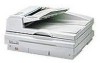
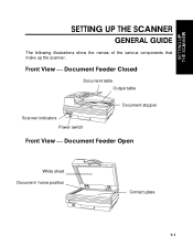
Front View Document Feeder Closed Document table Output table Document stopper Scanner indicators Power switch Front View Document Feeder Open White sheet Document home position Contact glass 1-1 SETTING UP THE SCANNER SETTING UP THE SCANNER GENERAL GUIDE The following illustrations show the names of the various components that make up the scanner.
Front View Document Feeder Closed Document table Output table Document stopper Scanner indicators Power switch Front View Document Feeder Open White sheet Document home position Contact glass 1-1 SETTING UP THE SCANNER SETTING UP THE SCANNER GENERAL GUIDE The following illustrations show the names of the various components that make up the scanner.
Operation Manual
Page 16
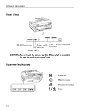
Scanner Indicators Power on Machine busy Document in place Error 1-2 SETTING UP THE SCANNER Rear View RS-232C connector Rotary switch SCSI Power cord socket DIP switches connectors Service switch CAUTION: Do not touch the service switch. This switch is provided for use by service personnel only.
Scanner Indicators Power on Machine busy Document in place Error 1-2 SETTING UP THE SCANNER Rear View RS-232C connector Rotary switch SCSI Power cord socket DIP switches connectors Service switch CAUTION: Do not touch the service switch. This switch is provided for use by service personnel only.
Operation Manual
Page 17
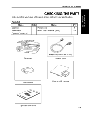
Parts list Name Scanner Terminator Operator's manual Q'ty Name 1 Power cord 1 driver soft & manual (ISIS) 1 Q'ty 1 1set Scanner Power cord Terminator driver soft & manual Operator's manual 1-3 SETTING UP THE SCANNER CHECKING THE PARTS Make sure that you have all the parts shown below in your packing box.
Parts list Name Scanner Terminator Operator's manual Q'ty Name 1 Power cord 1 driver soft & manual (ISIS) 1 Q'ty 1 1set Scanner Power cord Terminator driver soft & manual Operator's manual 1-3 SETTING UP THE SCANNER CHECKING THE PARTS Make sure that you have all the parts shown below in your packing box.
Operation Manual
Page 18
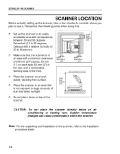
..., and a comfortable working area in the front. Ë Place the scanner on a level, stable, vibrating-free surface. Ë Place the scanner in an area with a minimum clearance of the scanner. Remember the following points when doing this. Ë Set up the scanner, take a few minutes to consider where you plan to use it... between 50 and 90 degrees Fahrenheit (10 to 32 degrees Celsius) with a relative humidity of 20 to 80 percent. Ë Make sure that the scanner is in an area that is not exposed to the installation procedure sheet. 1-4 more than 600mm (24") CAUTION: Do not place the...
..., and a comfortable working area in the front. Ë Place the scanner on a level, stable, vibrating-free surface. Ë Place the scanner in an area with a minimum clearance of the scanner. Remember the following points when doing this. Ë Set up the scanner, take a few minutes to consider where you plan to use it... between 50 and 90 degrees Fahrenheit (10 to 32 degrees Celsius) with a relative humidity of 20 to 80 percent. Ë Make sure that the scanner is in an area that is not exposed to the installation procedure sheet. 1-4 more than 600mm (24") CAUTION: Do not place the...

Operation Manual
Page 19
Note the following procedure to connect the scanner to your scanner's certification and can be capped with a terminator. Note:The RS-232C connector is employed only when the optional Operation Panel is being connected before making ... established for this equipment. Ë The total length of the SCSI bus should not exceed six meters. Ë Either of the scanner's two SCSI connectors can cause interference levels that the scanner and all the other devices in the SCSI chain are turned off. 1-5 To connect to a host computer using a SCSI cable...
Note the following procedure to connect the scanner to your scanner's certification and can be capped with a terminator. Note:The RS-232C connector is employed only when the optional Operation Panel is being connected before making ... established for this equipment. Ë The total length of the SCSI bus should not exceed six meters. Ë Either of the scanner's two SCSI connectors can cause interference levels that the scanner and all the other devices in the SCSI chain are turned off. 1-5 To connect to a host computer using a SCSI cable...
Operation Manual
Page 20
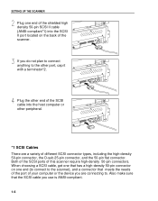
... the other peripheral. *1 SCSI Cables There are a variety of your computer or the device you are connecting to. Both of the SCSI ports of the scanner. Plug the other end of the SCSI cable into the SCSI II port located on one end of the shielded high density 50-pin SCSI... 25-pin connector, and the 50-pin flat connector. Also make sure that the SCSI cable you do not plan to connect anything to the scanner), and a connector that has a high-density 50-pin connector on the back of this...
... the other peripheral. *1 SCSI Cables There are a variety of your computer or the device you are connecting to. Both of the SCSI ports of the scanner. Plug the other end of the SCSI cable into the SCSI II port located on one end of the shielded high density 50-pin SCSI... 25-pin connector, and the 50-pin flat connector. Also make sure that the SCSI cable you do not plan to connect anything to the scanner), and a connector that has a high-density 50-pin connector on the back of this...

Operation Manual
Page 21
If you connect this scanner at each end of a SCSI chain. If the scanner is located inside of a SCSI chain that is already terminated, you do not need to terminate the scanner's other port. 1-7 SETTING UP THE SCANNER *2 Terminators Generally you need to have two terminators at the end of a SCSI chain, you should cap the scanner's unused SCSI port with a terminator.
If you connect this scanner at each end of a SCSI chain. If the scanner is located inside of a SCSI chain that is already terminated, you do not need to terminate the scanner's other port. 1-7 SETTING UP THE SCANNER *2 Terminators Generally you need to have two terminators at the end of a SCSI chain, you should cap the scanner's unused SCSI port with a terminator.
Operation Manual
Page 22
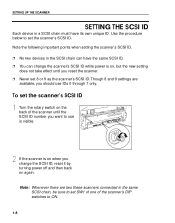
... same SCSI ID. Ë You can have its own unique ID. Use the procedure below to ON. 1-8 Note the following important points when setting the scanner's SCSI ID. Ë No two devices in the same SCSI chain, be sure to set SW1 of one of the... scanner until the SCSI ID number you want to use IDs 0 through 7 only. Though 8 and 9 settings are two these scanners connected in the SCSI chain can change the SCSI ID, reset it by turning power off...
... same SCSI ID. Ë You can have its own unique ID. Use the procedure below to ON. 1-8 Note the following important points when setting the scanner's SCSI ID. Ë No two devices in the same SCSI chain, be sure to set SW1 of one of the... scanner until the SCSI ID number you want to use IDs 0 through 7 only. Though 8 and 9 settings are two these scanners connected in the SCSI chain can change the SCSI ID, reset it by turning power off...
Operation Manual
Page 23
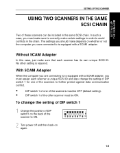
... the same SCSI chain. The settings you should make depends on whether or not the computer you care connected to correctly make sure that each scanner a unique SCSI ID and also change the setting of DIP switch 1 Change the position of DIP switch1 on again. 1-9 In such a case, ...SCAM adapter. With SCAM Adapter When the computer you are connecting to is equipped with a SCAM adapter, you must assign each scanner has its own unique SCSI ID. No other scanner must be OFF (default setting). • DIP switch 1 of the other setting is required. Turn power off and then back...
... the same SCSI chain. The settings you should make depends on whether or not the computer you care connected to correctly make sure that each scanner a unique SCSI ID and also change the setting of DIP switch 1 Change the position of DIP switch1 on again. 1-9 In such a case, ...SCAM adapter. With SCAM Adapter When the computer you are connecting to is equipped with a SCAM adapter, you must assign each scanner has its own unique SCSI ID. No other scanner must be OFF (default setting). • DIP switch 1 of the other setting is required. Turn power off and then back...
Operation Manual
Page 24
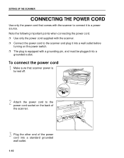
... the other end of the scanner. Note the following important points when connecting the power cord. Ë Use only the power cord supplied with the scanner. Ë Connect the power cord to the scanner and plug it to a power source. SETTING UP THE SCANNER CONNECTING THE POWER CORD Use only... the power cord that scanner power is equipped with the scanner to connect it into a wall outlet before turning...
... the other end of the scanner. Note the following important points when connecting the power cord. Ë Use only the power cord supplied with the scanner. Ë Connect the power cord to the scanner and plug it to a power source. SETTING UP THE SCANNER CONNECTING THE POWER CORD Use only... the power cord that scanner power is equipped with the scanner to connect it into a wall outlet before turning...
Operation Manual
Page 25
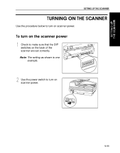
Use the power switch to turn on scanner power. Note: The setting as shown is one example. SETTING UP THE SCANNER TURNING ON THE SCANNER Use the procedure below to turn on scanner power. 1-11 To turn on the scanner power Check to make sure that the DIP switches on the back of the scanner are set correctly.
Use the power switch to turn on scanner power. Note: The setting as shown is one example. SETTING UP THE SCANNER TURNING ON THE SCANNER Use the procedure below to turn on scanner power. 1-11 To turn on the scanner power Check to make sure that the DIP switches on the back of the scanner are set correctly.
Operation Manual
Page 26
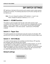
...DIP switch to its ON position to enable IS410 emulation. If your software dealer. SETTING UP THE SCANNER DIP SWITCH SETTINGS DIP switches on the back of the scanner can set to OFF(SCAM enabled). We recommend that can change the settings of differences between Normal ... 6, 7, or 8. The following describes the DIP switch settings that you obtain the appropriate driver from your application's driver supports the IS410 but not this scanner model connected in the same SCSI chain, and the computer is used to ON (SCAM disabled), while Switch 1 of DIP switches 1, 3, and 4 only...
...DIP switch to its ON position to enable IS410 emulation. If your software dealer. SETTING UP THE SCANNER DIP SWITCH SETTINGS DIP switches on the back of the scanner can set to OFF(SCAM enabled). We recommend that can change the settings of differences between Normal ... 6, 7, or 8. The following describes the DIP switch settings that you obtain the appropriate driver from your application's driver supports the IS410 but not this scanner model connected in the same SCSI chain, and the computer is used to ON (SCAM disabled), while Switch 1 of DIP switches 1, 3, and 4 only...

Operation Manual
Page 27
SETTING UP THE SCANNER 1-13 To change DIP switch settings Turn off the scanner and make the DIP switch settings described above. Turn the scanner back on.
SETTING UP THE SCANNER 1-13 To change DIP switch settings Turn off the scanner and make the DIP switch settings described above. Turn the scanner back on.


