

Operation Manual
Page 2
... Regulations. Note to users in Canada This Class B digital apparatus meets all rights in a residential installation. Copyright © Copyright, 1997 Ricoh Co., Ltd. Warnig Changes or modifications not expressly approved by any means, electronic, mechanical, photocopying, recording, or otherwise, without prior notice...or by the manufacturer could void the user's authority to Part 15 of their respective companies. Caution Properly shielded and grounded cable and connector must be trademarks of the FCC Rules. Cet appareil mumérique de la Classe B respecte toutes les ...
... Regulations. Note to users in Canada This Class B digital apparatus meets all rights in a residential installation. Copyright © Copyright, 1997 Ricoh Co., Ltd. Warnig Changes or modifications not expressly approved by any means, electronic, mechanical, photocopying, recording, or otherwise, without prior notice...or by the manufacturer could void the user's authority to Part 15 of their respective companies. Caution Properly shielded and grounded cable and connector must be trademarks of the FCC Rules. Cet appareil mumérique de la Classe B respecte toutes les ...
Operation Manual
Page 19
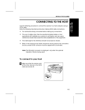
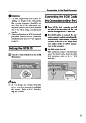
... Ë Turn all the other devices in the SCSI chain are turned off. 1-5 To connect to a host computer using a SCSI cable. SETTING UP THE SCANNER CONNECTING TO THE HOST Use the following important points when making any unused SCSI connector must be used for this ...equipment. Ë The total length of the SCSI bus should not exceed six meters. Ë Either of cables other than the specified shielded cables or their equivalents will invalidate your scanner's certification and can be capped with a terminator. Note the following procedure to connect the scanner...
... Ë Turn all the other devices in the SCSI chain are turned off. 1-5 To connect to a host computer using a SCSI cable. SETTING UP THE SCANNER CONNECTING TO THE HOST Use the following important points when making any unused SCSI connector must be used for this ...equipment. Ë The total length of the SCSI bus should not exceed six meters. Ë Either of cables other than the specified shielded cables or their equivalents will invalidate your scanner's certification and can be capped with a terminator. Note the following procedure to connect the scanner...
Operation Manual
Page 20
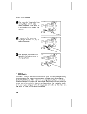
... are connecting to the other port, cap it with a terminator*2. 4 Plug the other end of the SCSI cable into the SCSI II port located on one end of the shielded high density 50-pin SCSI II... cable (ANSI-compliant*1) into the host computer or other peripheral. *1 SCSI Cables There are a variety of different SCSI connector types, including the high-density 50-pin connector, the ...the SCSI ports of this scanner require high-density 50-pin connectors. Also make sure that the SCSI cable you use is ANSI-compliant. 1-6
... are connecting to the other port, cap it with a terminator*2. 4 Plug the other end of the SCSI cable into the SCSI II port located on one end of the shielded high density 50-pin SCSI II... cable (ANSI-compliant*1) into the host computer or other peripheral. *1 SCSI Cables There are a variety of different SCSI connector types, including the high-density 50-pin connector, the ...the SCSI ports of this scanner require high-density 50-pin connectors. Also make sure that the SCSI cable you use is ANSI-compliant. 1-6

Operation Manual
Page 50
... roller set correctly. Ë Verify that you have the SCSI Terminator attached correctly. Ë Check to an appropriate power outlet. Ë Make sure the SCSI cable is connected properly. Ë Check that the host computer is operating correctly. Ë Make sure the SCSI ID is correct. Ë Make sure the DIP...
... roller set correctly. Ë Verify that you have the SCSI Terminator attached correctly. Ë Check to an appropriate power outlet. Ë Make sure the SCSI cable is connected properly. Ë Check that the host computer is operating correctly. Ë Make sure the SCSI ID is correct. Ë Make sure the DIP...

Operation Manual
Page 53
... computer, on the SCSI II Terminator plug you must connect a SCSI II terminator plug to provide the SCSI II cable. SCANNER SPECIFICATIONS ,17(5)$&(6 This section provides information on the shielded high density 50-pin SCSI II cable you use on your machine, and on the RS-232C interface. The SCSI II... cable is your responsibility to make sure that you have a SCSI II port available on the host computer and to the ...
... computer, on the SCSI II Terminator plug you must connect a SCSI II terminator plug to provide the SCSI II cable. SCANNER SPECIFICATIONS ,17(5)$&(6 This section provides information on the shielded high density 50-pin SCSI II cable you use on your machine, and on the RS-232C interface. The SCSI II... cable is your responsibility to make sure that you have a SCSI II port available on the host computer and to the ...
Operation Manual
Page 54
... terminator is a standard SCSI II Terminator plug and is a standard SCSI II interface and requires a shielded high density 50-pin SCSI II bus and tag cable with the scanner.
... terminator is a standard SCSI II Terminator plug and is a standard SCSI II interface and requires a shielded high density 50-pin SCSI II bus and tag cable with the scanner.
Operation Manual
Page 55
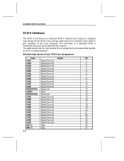
... 30 31 32 33 34 35 36 37 38 39 40 41 42 43 44 45 46 47 48 49 50 SCSI II Terminator specifications A Cable Single-Ended Active high density 50-pin Scanner Terminator plug SCSI II, high density narrow terminator with internal shield, all plastic cover, low profile with...
... 30 31 32 33 34 35 36 37 38 39 40 41 42 43 44 45 46 47 48 49 50 SCSI II Terminator specifications A Cable Single-Ended Active high density 50-pin Scanner Terminator plug SCSI II, high density narrow terminator with internal shield, all plastic cover, low profile with...
Operation Manual
Page 56
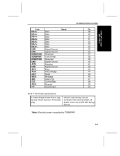
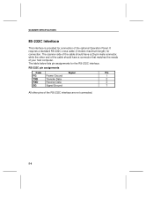
The scanner side of the cable should have a 25-pin male connector, while the other pins of the optional Operation Panel. The table below lists pin assignments for connection of the ... connected. 5-6 RS-232C pin assignments Code Signal Pin FG Frame Ground 1 TXD Transfer Data 2 RXD Receive Data 3 SG Signal Ground 7 All other end of the cable should have a connector that matches the needs of your host computer. SCANNER SPECIFICATIONS RS-232C Interface This interface is provided for the RS-232C interface...
The scanner side of the cable should have a 25-pin male connector, while the other pins of the optional Operation Panel. The table below lists pin assignments for connection of the ... connected. 5-6 RS-232C pin assignments Code Signal Pin FG Frame Ground 1 TXD Transfer Data 2 RXD Receive Data 3 SG Signal Ground 7 All other end of the cable should have a connector that matches the needs of your host computer. SCANNER SPECIFICATIONS RS-232C Interface This interface is provided for the RS-232C interface...
Operation Manual
Page 8
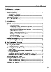
... SCSI 10 SCSI Connection Requirements for the Scanner 10 Setting the SCSI ID 11 Connecting the SCSI Cable (No Connection to Other Port 11 Connecting the SCSI Cable (Connection to Other Port 12 Connecting the Power Cable 13 Turning On/Off the Scanner Power 15 Turning On the Scanner Power 15 Turning Off...
... SCSI 10 SCSI Connection Requirements for the Scanner 10 Setting the SCSI ID 11 Connecting the SCSI Cable (No Connection to Other Port 11 Connecting the SCSI Cable (Connection to Other Port 12 Connecting the Power Cable 13 Turning On/Off the Scanner Power 15 Turning On the Scanner Power 15 Turning Off...
Operation Manual
Page 15
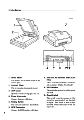
Rotary Switch This switch is used to set the operating mode. 9. SCSI Connector Connect the SCSI interface cable here. 4 7. This switch is used to clear paper jams, etc. 4. DIP Switches These switches are used to make new DIP switch and rotary switch ...settings valid. ADF Cover Open this cover to set the SCSI ID. 6. Power Connector Connect the power cable here. 5. 1. Interface for Reverse Side Scanning This is placed. 3. Contact Glass This is where the document is an extension interface for reverse side scanning. (...
Rotary Switch This switch is used to set the operating mode. 9. SCSI Connector Connect the SCSI interface cable here. 4 7. This switch is used to clear paper jams, etc. 4. DIP Switches These switches are used to make new DIP switch and rotary switch ...settings valid. ADF Cover Open this cover to set the SCSI ID. 6. Power Connector Connect the power cable here. 5. 1. Interface for Reverse Side Scanning This is placed. 3. Contact Glass This is where the document is an extension interface for reverse side scanning. (...

Operation Manual
Page 21
... must be set the ID. What is used for highspeed data transfer between a peripheral device and a host computer. • In a SCSI connection, ANSI-compliant SCSI cables are using a SCSI board and driver software that does not duplicate the SCSI ID of another device that does not have a SCAM function, it will...if the SCSI ID is no need to a host personal computer through a SCSI interface. ments for this scanner that supports SCAM, the SCSI ID of cables and SCSI boards will be set the SCSI ID for the device before turning on the power and before turning on the computer. • The...
... must be set the ID. What is used for highspeed data transfer between a peripheral device and a host computer. • In a SCSI connection, ANSI-compliant SCSI cables are using a SCSI board and driver software that does not duplicate the SCSI ID of another device that does not have a SCAM function, it will...if the SCSI ID is no need to a host personal computer through a SCSI interface. ments for this scanner that supports SCAM, the SCSI ID of cables and SCSI boards will be set the SCSI ID for the device before turning on the power and before turning on the computer. • The...
Operation Manual
Page 22
...the Scanner." 11 Connecting to the Host Computer Important Ì The total length of the cable inside the personal computer, should be connected through the SCSI interface. cluding the length of the SCSI cables, in daisy chain fashion, with this scanner at the end of the daisy chain. (...Set DIP switch 3 to off the host computer and all peripheral devices that are connected simultaneously may not work together properly. Connecting the SCSI Cable (No Connection to initialize the scanner. For details on , it is on the functions of SCSI boards and peripheral devices that will be ...
...the Scanner." 11 Connecting to the Host Computer Important Ì The total length of the cable inside the personal computer, should be connected through the SCSI interface. cluding the length of the SCSI cables, in daisy chain fashion, with this scanner at the end of the daisy chain. (...Set DIP switch 3 to off the host computer and all peripheral devices that are connected simultaneously may not work together properly. Connecting the SCSI Cable (No Connection to initialize the scanner. For details on , it is on the functions of SCSI boards and peripheral devices that will be ...
Operation Manual
Page 23
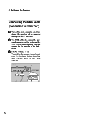
For details on . Setting up the Scanner Connecting the SCSI Cable (Connection to P.43, "DIP Switches." 12 This disables the scanner's internal terminator. B Use SCSI cables to on the functions of the daisy chain. C Set DIP switch 3 to connect the personal computer and the peripheral devices in daisy chain fashion, with this scanner in the middle of the DIP switches, refer to Other Port) A Turn off the host computer and all pe- 2. ripheral devices that will be connected through the SCSI interface.
For details on . Setting up the Scanner Connecting the SCSI Cable (Connection to P.43, "DIP Switches." 12 This disables the scanner's internal terminator. B Use SCSI cables to on the functions of the daisy chain. C Set DIP switch 3 to connect the personal computer and the peripheral devices in daisy chain fashion, with this scanner in the middle of the DIP switches, refer to Other Port) A Turn off the host computer and all pe- 2. ripheral devices that will be connected through the SCSI interface.
Operation Manual
Page 24
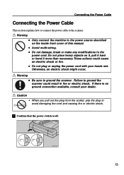
... section explains how to connect the power cable to avoid damaging the cord and causing fire or electric shock. If there is off. 13 Do not place heavy objects on the inside front ...
... section explains how to connect the power cable to avoid damaging the cord and causing fire or electric shock. If there is off. 13 Do not place heavy objects on the inside front ...
Operation Manual
Page 25
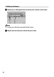
Setting up the Scanner B Push the power cable plug all of the power cable into the power connector on the scanner. Note Ì Use the power cable that was provided with this scanner. C Plug the other end of the way into the power outlet. 14 2.
Setting up the Scanner B Push the power cable plug all of the power cable into the power connector on the scanner. Note Ì Use the power cable that was provided with this scanner. C Plug the other end of the way into the power outlet. 14 2.
Operation Manual
Page 38
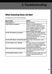
... set a unique SCSI ID for the scanner. Refer to the manual or help information for your scanner driver. Are the SCSI cables connected securey? Refer to recognize the scanner if it has the same SCSI ID as another device. Refer to check Action Is the ...For details on the power. 5. Are the indicators on ? Is the scanner driver selected properly? Are the software settings correct? If there are any cables are on or flashing. Troubleshooting When Scanning Does not Start If scanning does not start, check the following: Item to P.11, "Setting the SCSI ID...
... set a unique SCSI ID for the scanner. Refer to the manual or help information for your scanner driver. Are the SCSI cables connected securey? Refer to recognize the scanner if it has the same SCSI ID as another device. Refer to check Action Is the ...For details on the power. 5. Are the indicators on ? Is the scanner driver selected properly? Are the software settings correct? If there are any cables are on or flashing. Troubleshooting When Scanning Does not Start If scanning does not start, check the following: Item to P.11, "Setting the SCSI ID...
Operation Manual
Page 41
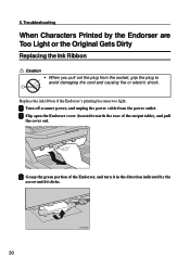
Troubleshooting When Characters Printed by the arrow until it clicks. 30 A Turn off scanner power, and unplug the power cable from the socket, grip the plug to avoid damaging the cord and causing fire or electric shock. 5. C Grasp the green portion of the output table), ...
Troubleshooting When Characters Printed by the arrow until it clicks. 30 A Turn off scanner power, and unplug the power cable from the socket, grip the plug to avoid damaging the cord and causing fire or electric shock. 5. C Grasp the green portion of the output table), ...
Operation Manual
Page 45
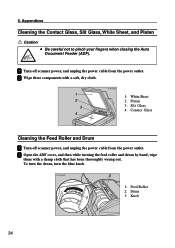
... 2: Platen 3: Slit Glass 4: Contact Glass Cleaning the Feed Roller and Drum A Turn off scanner power, and unplug the power cable from the power outlet. A Turn off scanner power, and unplug the power cable from the power outlet. Appendices Cleaning the Contact Glass, Slit Glass, White Sheet, and Platen Caution • Be careful...
... 2: Platen 3: Slit Glass 4: Contact Glass Cleaning the Feed Roller and Drum A Turn off scanner power, and unplug the power cable from the power outlet. A Turn off scanner power, and unplug the power cable from the power outlet. Appendices Cleaning the Contact Glass, Slit Glass, White Sheet, and Platen Caution • Be careful...
Operation Manual
Page 47
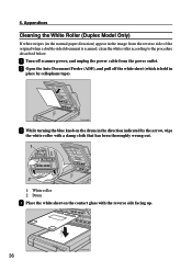
B Open the Auto Document Feeder (ADF), and pull off scanner power, and unplug the power cable from the reverse side of the original when a double-sided document is held in the image from the power outlet. C While turning the blue knob ...
B Open the Auto Document Feeder (ADF), and pull off scanner power, and unplug the power cable from the reverse side of the original when a double-sided document is held in the image from the power outlet. C While turning the blue knob ...
Operation Manual
Page 50
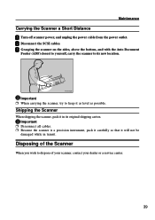
..., carry the scanner to its original shipping carton. Shipping the Scanner When shipping the scanner, pack it in transit. B Disconnect the SCSI cables. Important Ì When carrying the scanner, try to dispose of your scanner, contact your dealer or a service center. 39 Disposing of the... in its new location. Maintenance Carrying the Scanner a Short Distance A Turn off scanner power, and unplug the power cable from the power outlet. Important Ì Disconnect all cables. Ì Because the scanner is a precision instrument, pack it carefully so that it as level as possible.
..., carry the scanner to its original shipping carton. Shipping the Scanner When shipping the scanner, pack it in transit. B Disconnect the SCSI cables. Important Ì When carrying the scanner, try to dispose of your scanner, contact your dealer or a service center. 39 Disposing of the... in its new location. Maintenance Carrying the Scanner a Short Distance A Turn off scanner power, and unplug the power cable from the power outlet. Important Ì Disconnect all cables. Ì Because the scanner is a precision instrument, pack it carefully so that it as level as possible.