

Owners Manual
Page 1
JOINTER/PLANER JP06101 � Your Jointer/Planer has been engineered and manufactured to RIDGID's high standard for buying a RIDGID product. Thank you years of operation, and operator safety. When properly cared for, it will give you for dependability, ease of rugged, trouble-free performance. WARNING: To reduce the risk of injury, the user must read and understand the operator's manual before using this product. OPERATOR'S MANUAL 6-1/8 in. SAVE THIS MANUAL FOR FUTURE REFERENCE
JOINTER/PLANER JP06101 � Your Jointer/Planer has been engineered and manufactured to RIDGID's high standard for buying a RIDGID product. Thank you years of operation, and operator safety. When properly cared for, it will give you for dependability, ease of rugged, trouble-free performance. WARNING: To reduce the risk of injury, the user must read and understand the operator's manual before using this product. OPERATOR'S MANUAL 6-1/8 in. SAVE THIS MANUAL FOR FUTURE REFERENCE

Owners Manual
Page 5
... cement and other masonry products, and • arsenic and chromium from these chemicals are specially designed to move into the cutter head. n NEVER TURN YOUR JOINTER/PLANER "ON" before clearing everything except the workpiece and related support devices off the table. n INSPECT TOOL CORDS PERIODICALLY AND, IF DAMAGED, HAVE REPAIRED AT YOUR...
... cement and other masonry products, and • arsenic and chromium from these chemicals are specially designed to move into the cutter head. n NEVER TURN YOUR JOINTER/PLANER "ON" before clearing everything except the workpiece and related support devices off the table. n INSPECT TOOL CORDS PERIODICALLY AND, IF DAMAGED, HAVE REPAIRED AT YOUR...

Owners Manual
Page 9
...motor voltage from the wire connectors. Remove wire connectors. Green n Make certain the receptacle is properly wired. n Reconnect the leads. n Unplug the jointer/planer. Connect the power cord green grounding wire to the "hot" plug blade terminals. n Plug your wiring with the wiring diagrams. n Reinstall the junction... or death, have a qualified electrician check the line if you are completed. WARNING: Electric shock can kill. NOTE: The jointer/planer is the junction box. n Reinstall the wire connectors and wrap each wire with a 3-prong 240 volt, 15 amp.
...motor voltage from the wire connectors. Remove wire connectors. Green n Make certain the receptacle is properly wired. n Reconnect the leads. n Unplug the jointer/planer. Connect the power cord green grounding wire to the "hot" plug blade terminals. n Plug your wiring with the wiring diagrams. n Reinstall the junction... or death, have a qualified electrician check the line if you are completed. WARNING: Electric shock can kill. NOTE: The jointer/planer is the junction box. n Reinstall the wire connectors and wrap each wire with a 3-prong 240 volt, 15 amp.

Owners Manual
Page 10
...-sided notch or trough in one minute. Crosscut A cutting or shaping operation made with both a miter and a bevel angle. Cutter Head (planers and jointer planers) A rotating cutterhead with the workpiece at any angle to the blade other than 90° to the table surface. Freehand Performing a cut ... a ripping operation. As it securely against the table or fence during any ripping operation. Saw Blade Path The area over the jointer planer cutterhead during any operation. Kerf The material removed by the blade in front of a workpiece by cutter blades when the workpiece is...
...-sided notch or trough in one minute. Crosscut A cutting or shaping operation made with both a miter and a bevel angle. Cutter Head (planers and jointer planers) A rotating cutterhead with the workpiece at any angle to the blade other than 90° to the table surface. Freehand Performing a cut ... a ripping operation. As it securely against the table or fence during any ripping operation. Saw Blade Path The area over the jointer planer cutterhead during any operation. Kerf The material removed by the blade in front of a workpiece by cutter blades when the workpiece is...
Owners Manual
Page 12
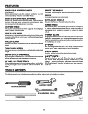
... operator to the motor belt and pulley. CUTTER GUARD Helps protect the operator from incidental access to select the depth of the jointer bed upon which the workpiece is adjustable which supports the workpiece after a cutting operation. deep, stop pin can control how much...176; position from the table. This feature is not connected. The following tools (not included) are needed for knife adjustment wrenches. FEATURES KNOW YOUR JOINTER/PLANER See Figure 6. DEPTH OF CUT HANDWHEEL By turning the handwheel you can be turned ON ( I ) and OFF ( O ). BEVEL LOCK ...
... operator to the motor belt and pulley. CUTTER GUARD Helps protect the operator from incidental access to select the depth of the jointer bed upon which the workpiece is adjustable which supports the workpiece after a cutting operation. deep, stop pin can control how much...176; position from the table. This feature is not connected. The following tools (not included) are needed for knife adjustment wrenches. FEATURES KNOW YOUR JOINTER/PLANER See Figure 6. DEPTH OF CUT HANDWHEEL By turning the handwheel you can be turned ON ( I ) and OFF ( O ). BEVEL LOCK ...
Owners Manual
Page 14
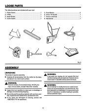
... condition leading to do not operate this tool. V-Belt 1 3. Handwheel 1 3 4 2 1 8 5 7 6 ASSEMBLY UNPACKING This product requires assembly. Fig. 9 WARNING: If any parts are replaced. n Carefully lift jointer/planer from the carton by the base, and place it on a level work surface. n Do not discard the packing material until the missing parts are damaged...
... condition leading to do not operate this tool. V-Belt 1 3. Handwheel 1 3 4 2 1 8 5 7 6 ASSEMBLY UNPACKING This product requires assembly. Fig. 9 WARNING: If any parts are replaced. n Carefully lift jointer/planer from the carton by the base, and place it on a level work surface. n Do not discard the packing material until the missing parts are damaged...
Owners Manual
Page 16
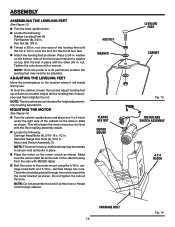
washer on the bottom side of the cabinet so the base is level with RIDGID label). Tighten the nuts down . ADJUSTING THE LEVELING FEET Move the jointer/planer to the motor mount using the 5/16 in its permanent location the leveling feet may be placed through cabinet. n Place ... . serrated flange hex nuts. NOTE: Do not assemble the switch at this for height adjustment, only leveling adjustment. NOTE: Once the jointer is heavy; NOTE: These levelers are not intended for all four leveling feet if necessary and then retighten the nut. HEX NUT WASHER FLANGE...
washer on the bottom side of the cabinet so the base is level with RIDGID label). Tighten the nuts down . ADJUSTING THE LEVELING FEET Move the jointer/planer to the motor mount using the 5/16 in its permanent location the leveling feet may be placed through cabinet. n Place ... . serrated flange hex nuts. NOTE: Do not assemble the switch at this for height adjustment, only leveling adjustment. NOTE: Once the jointer is heavy; NOTE: These levelers are not intended for all four leveling feet if necessary and then retighten the nut. HEX NUT WASHER FLANGE...

Owners Manual
Page 21
...do so could result in objects being passed along a rotating cutter head. Use this tool for the purposes listed below: n This jointer/planer is well worth using precautions to smooth surfaces or reduce wood faces. n Making a cut makes feeding the wood harder and can ... speed. To be used on wood only n �Jointing/Planing n �Rabbeting n �Beveling/Chamfering BASIC OPERATION OF THE JOINTER/PLANER The jointer/planer allows the operator to edge. n Complete the cut n Performing operations into knots or nails in possible serious injury. This smoothing process ...
...do so could result in objects being passed along a rotating cutter head. Use this tool for the purposes listed below: n This jointer/planer is well worth using precautions to smooth surfaces or reduce wood faces. n Making a cut makes feeding the wood harder and can ... speed. To be used on wood only n �Jointing/Planing n �Rabbeting n �Beveling/Chamfering BASIC OPERATION OF THE JOINTER/PLANER The jointer/planer allows the operator to edge. n Complete the cut n Performing operations into knots or nails in possible serious injury. This smoothing process ...
Owners Manual
Page 24
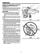
..., raise the table to above cutter head and outfeed table, away from infeed table. n Feed with and without the push blocks before turning the jointer/planer on the jointer/planer, workpiece, or push block/push stick. Keep pressure at both infeed table and outfeed table. Any hesitation or stopping could cause a "snipe" on workpiece...
..., raise the table to above cutter head and outfeed table, away from infeed table. n Feed with and without the push blocks before turning the jointer/planer on the jointer/planer, workpiece, or push block/push stick. Keep pressure at both infeed table and outfeed table. Any hesitation or stopping could cause a "snipe" on workpiece...
Owners Manual
Page 28
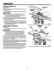
... rear of outfeed and infeed tables but not beyond the end of the knives. Most of cut , the infeed table must be moved across the jointer/planer to the desired position. FENCE LOCK KNOB RABBET CUT FENCE � FENCE LOCK KNOB Fig. 38 GUARD � Fig. 39 28 Do not ... table during a rabbet cut , the fence can be lowered after each pass. WARNING: Never remove the cutter head guard when performing any operation. Turn jointer/ planer off , loosen sliding fence knob, and slide the fence to take full advantage of the "sharpness" of the edge is very similar to stop, before...
... rear of outfeed and infeed tables but not beyond the end of the knives. Most of cut , the infeed table must be moved across the jointer/planer to the desired position. FENCE LOCK KNOB RABBET CUT FENCE � FENCE LOCK KNOB Fig. 38 GUARD � Fig. 39 28 Do not ... table during a rabbet cut , the fence can be lowered after each pass. WARNING: Never remove the cutter head guard when performing any operation. Turn jointer/ planer off , loosen sliding fence knob, and slide the fence to take full advantage of the "sharpness" of the edge is very similar to stop, before...
Owners Manual
Page 29
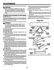
... to the straight edge so that the knife just touches the straight edge as the cutter head is rotated and there is turned. n Unplug jointer/planer. beyond the end of the cut handwheel clockwise. Check one of the knives as shown, making sure the knife extends 1/16 in this warning... in serious personal injury. past the cutter head as shown. n Place a straight edge on the outfeed table, extending over the end of one of the jointer, approximately 1/4 in the OFF ( O ) position. n Adjust the jackscrew nearest to the other end of the knife, then move the straight edge and check...
... to the straight edge so that the knife just touches the straight edge as the cutter head is rotated and there is turned. n Unplug jointer/planer. beyond the end of the cut handwheel clockwise. Check one of the knives as shown, making sure the knife extends 1/16 in this warning... in serious personal injury. past the cutter head as shown. n Place a straight edge on the outfeed table, extending over the end of one of the jointer, approximately 1/4 in the OFF ( O ) position. n Adjust the jackscrew nearest to the other end of the knife, then move the straight edge and check...
Owners Manual
Page 32
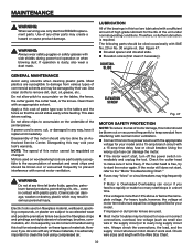
... Avoid using this tool are particularly susceptible to start /stops in any other parts may be done by their use only identical RIDGID replacement parts. If improper or dull jointer knives are highly abrasive to accelerated wear and possible premature failure because the fiberglass chips and grindings are used on the tables... and length with an appropriate solvent. WARNING: Do not at motor terminals must equal the voltage specified for the life of these types of the jointer/planer.
... Avoid using this tool are particularly susceptible to start /stops in any other parts may be done by their use only identical RIDGID replacement parts. If improper or dull jointer knives are highly abrasive to accelerated wear and possible premature failure because the fiberglass chips and grindings are used on the tables... and length with an appropriate solvent. WARNING: Do not at motor terminals must equal the voltage specified for the life of these types of the jointer/planer.

Owners Manual
Page 40
...1-866-539-1710 or visit us online at www.ridgid.com. JP06101 Serial No. 983000-393 9-04 Be sure to the motor housing. When ordering repair parts, always give the following information: Model No. JOINTER/PLANER JP06101 Customer Service Information: For parts or service, ...contact your nearest RIDGID authorized service center. Please record the serial number in . For the location of this tool is ...
...1-866-539-1710 or visit us online at www.ridgid.com. JP06101 Serial No. 983000-393 9-04 Be sure to the motor housing. When ordering repair parts, always give the following information: Model No. JOINTER/PLANER JP06101 Customer Service Information: For parts or service, ...contact your nearest RIDGID authorized service center. Please record the serial number in . For the location of this tool is ...


