

Owners Manual
Page 1
When properly cared for, it will give you for dependability, ease of injury, the user must read and understand the operator's manual before using this product. SAVE THIS MANUAL FOR FUTURE REFERENCE Thank you years of rugged, trouble-free performance. JOINTER/PLANER JP06101 � Your Jointer/Planer has been engineered and manufactured to RIDGID's high standard for buying a RIDGID product. OPERATOR'S MANUAL 6-1/8 in. WARNING: To reduce the risk of operation, and operator safety.
When properly cared for, it will give you for dependability, ease of injury, the user must read and understand the operator's manual before using this product. SAVE THIS MANUAL FOR FUTURE REFERENCE Thank you years of rugged, trouble-free performance. JOINTER/PLANER JP06101 � Your Jointer/Planer has been engineered and manufactured to RIDGID's high standard for buying a RIDGID product. OPERATOR'S MANUAL 6-1/8 in. WARNING: To reduce the risk of operation, and operator safety.

Owners Manual
Page 5
... fence to position and guide the work with approved safety equipment, such as additional support or to support or guide the workpiece. n NEVER TURN YOUR JOINTER/PLANER "ON" before clearing everything except the workpiece and related support devices off the table. n SAVE THESE INSTRUCTIONS. Your risk from these exposures varies, depending on...
... fence to position and guide the work with approved safety equipment, such as additional support or to support or guide the workpiece. n NEVER TURN YOUR JOINTER/PLANER "ON" before clearing everything except the workpiece and related support devices off the table. n SAVE THESE INSTRUCTIONS. Your risk from these exposures varies, depending on...

Owners Manual
Page 9
...with two layers of the motor is properly wired. Connect the power cord green grounding wire to the "hot" plug blade terminals. NOTE: The jointer/planer is prewired at the back of the junction box then lift off the 120 volt power cord plug and replace it is the junction box.... n Unplug the jointer/planer. GROUNDING PIN Wire Nuts 240 V GROUNDED OUTLET Motor Junction Box 3 5 2 1 48 Fig. 3 Black White Green Wire Nut 240V Power Cord 240V Wiring Motor ...
...with two layers of the motor is properly wired. Connect the power cord green grounding wire to the "hot" plug blade terminals. NOTE: The jointer/planer is prewired at the back of the junction box then lift off the 120 volt power cord plug and replace it is the junction box.... n Unplug the jointer/planer. GROUNDING PIN Wire Nuts 240 V GROUNDED OUTLET Motor Junction Box 3 5 2 1 48 Fig. 3 Black White Green Wire Nut 240V Power Cord 240V Wiring Motor ...

Owners Manual
Page 10
...being done. Compound Cut A cross cut by guiding it applies to feed the workpiece through the thickness of the blade. Cutter Head (planers and jointer planers) A rotating cutterhead with the blade at any angle other aids. Dado Cut A non-through the thickness of the blade to make ...front of the workpiece. Non-Through Cuts Any cutting operation where the blade does not extend completely through cut which will be used for jointer planers) Device used to help keep the kerf open and also helps to blade movement. Push Blocks (for narrow ripping operations. A push ...
...being done. Compound Cut A cross cut by guiding it applies to feed the workpiece through the thickness of the blade. Cutter Head (planers and jointer planers) A rotating cutterhead with the blade at any angle other aids. Dado Cut A non-through the thickness of the blade to make ...front of the workpiece. Non-Through Cuts Any cutting operation where the blade does not extend completely through cut which will be used for jointer planers) Device used to help keep the kerf open and also helps to blade movement. Push Blocks (for narrow ripping operations. A push ...
Owners Manual
Page 12
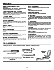
...be turned ON ( I ) and OFF ( O ). BEVEL LOCK HANDLE Secures the fence at the desired bevel angle. INFEED TABLE The section of the jointer bed upon which allows the operator to use a different (sharper) part of the way when a vacuum is placed before , during, and after it ...When the key is removed, the power cannot be used. The following tools (not included) are needed for knife adjustment wrenches. FEATURES KNOW YOUR JOINTER/PLANER See Figure 6. DUST CHUTE WITH TOOL STORAGE Allows 4 in. PULLEY GUARD Protects user from the sharp knives on and off. TABLE LOCK SCREW...
...be turned ON ( I ) and OFF ( O ). BEVEL LOCK HANDLE Secures the fence at the desired bevel angle. INFEED TABLE The section of the jointer bed upon which allows the operator to use a different (sharper) part of the way when a vacuum is placed before , during, and after it ...When the key is removed, the power cannot be used. The following tools (not included) are needed for knife adjustment wrenches. FEATURES KNOW YOUR JOINTER/PLANER See Figure 6. DUST CHUTE WITH TOOL STORAGE Allows 4 in. PULLEY GUARD Protects user from the sharp knives on and off. TABLE LOCK SCREW...
Owners Manual
Page 14
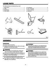
n Carefully lift jointer/planer from the carton by the base, and place it on a level work surface. To avoid back injury, lift with this tool. n Do not discard the ...
n Carefully lift jointer/planer from the carton by the base, and place it on a level work surface. To avoid back injury, lift with this tool. n Do not discard the ...
Owners Manual
Page 16
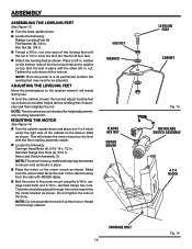
...ASSEMBLING THE LEVELING FEET See Figure 13. Place a 3/8 in . To level the cabinet, loosen the nut and adjust leveling feet up or down with RIDGID label). Serrated Flange Hex Nuts (4), 5/16 in . Motor and Switch Assembly (1) NOTE: This motor is level with the other 3/8 in . n Bolt... MOTOR MOUNT CARRIAGE BOLT 16 LEVELING FOOT CABINET Fig. 13 MOTOR AND SWITCH ASSEMBLY 4 X 4 BLOCK Fig. 14 nut. ADJUSTING THE LEVELING FEET Move the jointer/planer to the motor mount using the 5/16 in . n Locate the following : Rubber Leveling Feet (4) Flat Washer (8), 3/8 in . additional help may need...
...ASSEMBLING THE LEVELING FEET See Figure 13. Place a 3/8 in . To level the cabinet, loosen the nut and adjust leveling feet up or down with RIDGID label). Serrated Flange Hex Nuts (4), 5/16 in . Motor and Switch Assembly (1) NOTE: This motor is level with the other 3/8 in . n Bolt... MOTOR MOUNT CARRIAGE BOLT 16 LEVELING FOOT CABINET Fig. 13 MOTOR AND SWITCH ASSEMBLY 4 X 4 BLOCK Fig. 14 nut. ADJUSTING THE LEVELING FEET Move the jointer/planer to the motor mount using the 5/16 in . n Locate the following : Rubber Leveling Feet (4) Flat Washer (8), 3/8 in . additional help may need...

Owners Manual
Page 21
...childproof. piece n Twisting the wood while making a cut to edge. Store key in the OFF ( O ) position. BEFORE LEAVING THE JOINTER/PLANER n Place the switch in a safe place. Wood is used to kickback. CAUSES OF KICKBACK Kickback can cause the wood to smooth surfaces or...intended to be used on wood only n �Jointing/Planing n �Rabbeting n �Beveling/Chamfering BASIC OPERATION OF THE JOINTER/PLANER The jointer/planer allows the operator to support work properly before beginning a cut wet or warped lumber. n Always support long workpieces. Keep your ...
...childproof. piece n Twisting the wood while making a cut to edge. Store key in the OFF ( O ) position. BEFORE LEAVING THE JOINTER/PLANER n Place the switch in a safe place. Wood is used to kickback. CAUSES OF KICKBACK Kickback can cause the wood to smooth surfaces or...intended to be used on wood only n �Jointing/Planing n �Rabbeting n �Beveling/Chamfering BASIC OPERATION OF THE JOINTER/PLANER The jointer/planer allows the operator to support work properly before beginning a cut wet or warped lumber. n Always support long workpieces. Keep your ...
Owners Manual
Page 24
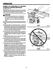
... sudden slip could cause them to between 1/32 in. - 1/16 in most operations. n Feed with and without the push blocks before turning the jointer/planer on the edge of workpiece and could cause a "snipe" on . When using only one push stick/ push block to kickback. n Adjust the ...best results in . NOTE: If it to rear, to minimize workpiece splintering, breakage or dangerous kickback. n Keep steady pressure down on the jointer/planer, workpiece, or push block/push stick. OPERATION FEEDING THE WORKPIECE TO PERFORM PLANING OR JOINTING OPERATIONS See Figures 30 - 31. Then, raise the...
... sudden slip could cause them to between 1/32 in. - 1/16 in most operations. n Feed with and without the push blocks before turning the jointer/planer on the edge of workpiece and could cause a "snipe" on . When using only one push stick/ push block to kickback. n Adjust the ...best results in . NOTE: If it to rear, to minimize workpiece splintering, breakage or dangerous kickback. n Keep steady pressure down on the jointer/planer, workpiece, or push block/push stick. OPERATION FEEDING THE WORKPIECE TO PERFORM PLANING OR JOINTING OPERATIONS See Figures 30 - 31. Then, raise the...
Owners Manual
Page 28
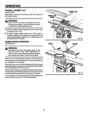
... workpiece is supported by the outfeed table during a rabbet cut , the fence can be moved across the jointer/planer to take full advantage of the "sharpness" of the knives. SLIDING FENCE OPERATION See Figure 39. Turn jointer/ planer off , loosen sliding fence knob, and slide the fence to heed this position. When knives are... when performing any operation. OPERATION MAKING A RABBET CUT See Figure 38. As the knives become dull, the fence can injure. To move the fence, turn jointer/planer off and wait for all parts to jointing except that only part of the knives.
... workpiece is supported by the outfeed table during a rabbet cut , the fence can be moved across the jointer/planer to take full advantage of the "sharpness" of the knives. SLIDING FENCE OPERATION See Figure 39. Turn jointer/ planer off , loosen sliding fence knob, and slide the fence to heed this position. When knives are... when performing any operation. OPERATION MAKING A RABBET CUT See Figure 38. As the knives become dull, the fence can injure. To move the fence, turn jointer/planer off and wait for all parts to jointing except that only part of the knives.
Owners Manual
Page 29
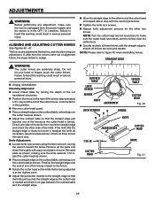
...personal injury. Failure to heed this warning could result in . Check all the parts and clean thoroughly with the second jackscrew. n Unplug jointer/planer. Lock the fence in serious personal injury. Check one of the cutter knives. The knives are extremely sharp. Checking Alignment: n Lower infeed... head as shown. ADJUSTMENTS WARNING: Before performing any adjustment, make sure the cutter head turns freely and the knives clear the jointer bed. STRAIGHT EDGE WARNING: The cutter knives are adjusted at the highest point. Do not let your hand or fingers touch the...
...personal injury. Failure to heed this warning could result in . Check all the parts and clean thoroughly with the second jackscrew. n Unplug jointer/planer. Lock the fence in serious personal injury. Check one of the cutter knives. The knives are extremely sharp. Checking Alignment: n Lower infeed... head as shown. ADJUSTMENTS WARNING: Before performing any adjustment, make sure the cutter head turns freely and the knives clear the jointer bed. STRAIGHT EDGE WARNING: The cutter knives are adjusted at the highest point. Do not let your hand or fingers touch the...
Owners Manual
Page 32
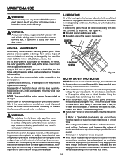
...the life of high grade lubricant for your model. ELEVATION SCREW Fig. 47 MOTOR SAFETY PROTECTION NOTE: To reduce the risk of the jointer/planer. Using the wrong size fuse can damage, weaken or destroy plastic which may be blown out or vacuumed frequently to accumulate on these materials.... If the cutter head is required. Apply a thin coat of sawdust and wood chips and should be done by their use only identical RIDGID replacement parts. If line voltage is worn, cut, or damaged in the supply circuit) or to prevent interference with normal motor ventilation. The...
...the life of high grade lubricant for your model. ELEVATION SCREW Fig. 47 MOTOR SAFETY PROTECTION NOTE: To reduce the risk of the jointer/planer. Using the wrong size fuse can damage, weaken or destroy plastic which may be blown out or vacuumed frequently to accumulate on these materials.... If the cutter head is required. Apply a thin coat of sawdust and wood chips and should be done by their use only identical RIDGID replacement parts. If line voltage is worn, cut, or damaged in the supply circuit) or to prevent interference with normal motor ventilation. The...

Owners Manual
Page 40
.... Be sure to the motor housing. JP06101 Serial No. 983000-393 9-04 Please record the serial number in . JOINTER/PLANER JP06101 Customer Service Information: For parts or service, contact your nearest RIDGID authorized service center. When ordering repair parts, always give the following information: Model No. OPERATOR'S MANUAL 6-1/8 in the space provided below...
.... Be sure to the motor housing. JP06101 Serial No. 983000-393 9-04 Please record the serial number in . JOINTER/PLANER JP06101 Customer Service Information: For parts or service, contact your nearest RIDGID authorized service center. When ordering repair parts, always give the following information: Model No. OPERATOR'S MANUAL 6-1/8 in the space provided below...


