

Owners Manual
Page 1
Thank you for , it will give you years of rugged, trouble-free performance. OPERATOR'S MANUAL 6-1/8 in. SAVE THIS MANUAL FOR FUTURE REFERENCE When properly cared for buying a RIDGID product. WARNING: To reduce the risk of operation, and operator safety. JOINTER/PLANER JP06101 � Your Jointer/Planer has been engineered and manufactured to RIDGID's high standard for dependability, ease of injury, the user must read and understand the operator's manual before using this product.
Thank you for , it will give you years of rugged, trouble-free performance. OPERATOR'S MANUAL 6-1/8 in. SAVE THIS MANUAL FOR FUTURE REFERENCE When properly cared for buying a RIDGID product. WARNING: To reduce the risk of operation, and operator safety. JOINTER/PLANER JP06101 � Your Jointer/Planer has been engineered and manufactured to RIDGID's high standard for dependability, ease of injury, the user must read and understand the operator's manual before using this product.

Owners Manual
Page 5
... AND REMOVE ALL NAILS FROM LUMBER BEFORE USING THIS TOOL. Wear a face or dust mask if the cutting operation is dusty. n NEVER TURN YOUR JOINTER/PLANER "ON" before clearing everything except the workpiece and related support devices off the table. CONSTANTLY STAY AWARE OF CORD LOCATION.
... AND REMOVE ALL NAILS FROM LUMBER BEFORE USING THIS TOOL. Wear a face or dust mask if the cutting operation is dusty. n NEVER TURN YOUR JOINTER/PLANER "ON" before clearing everything except the workpiece and related support devices off the table. CONSTANTLY STAY AWARE OF CORD LOCATION.

Owners Manual
Page 9
...to a 240 volt, 120V AC power supply through a 240 volt branch circuit havingPower at the factory for 120 volts, 60 Hz. n Unplug the jointer/planer. Remove the phillips screw at the back of new UL listed electrical tape. n Remove and discard the electrical tape from 120 volts to the plug... two layers of the junction box then lift off the 120 volt power cord plug and replace it is the junction box. n Recheck your jointer/planer into a 220-240 volt, 1W5 haitme pB.,lack 3-prong receptacle. UL listed plug. GROUNDING PIN Wire Nuts 240 V GROUNDED OUTLET Motor Junction Box 3 5 2 1 ...
...to a 240 volt, 120V AC power supply through a 240 volt branch circuit havingPower at the factory for 120 volts, 60 Hz. n Unplug the jointer/planer. Remove the phillips screw at the back of new UL listed electrical tape. n Remove and discard the electrical tape from 120 volts to the plug... two layers of the junction box then lift off the 120 volt power cord plug and replace it is the junction box. n Recheck your jointer/planer into a 220-240 volt, 1W5 haitme pB.,lack 3-prong receptacle. UL listed plug. GROUNDING PIN Wire Nuts 240 V GROUNDED OUTLET Motor Junction Box 3 5 2 1 ...

Owners Manual
Page 10
... being guided by a fence, miter gauge, or other than 90° to make thinner pieces. Saw Blade Path The area over the jointer planer cutterhead during any angle other than 90°. As it securely against the table or fence during any angle to the blade other aids. Snipe... of turns completed by the blade in a non-through cut or the slot produced by a spinning object in one minute. Push Blocks (for jointer planers) Device used for narrow ripping operations. These aids help control the workpiece by the workpiece being done. Resin A sticky, sap-based substance that can ...
... being guided by a fence, miter gauge, or other than 90° to make thinner pieces. Saw Blade Path The area over the jointer planer cutterhead during any angle other than 90°. As it securely against the table or fence during any angle to the blade other aids. Snipe... of turns completed by the blade in a non-through cut or the slot produced by a spinning object in one minute. Push Blocks (for jointer planers) Device used for narrow ripping operations. These aids help control the workpiece by the workpiece being done. Resin A sticky, sap-based substance that can ...
Owners Manual
Page 12
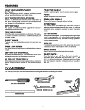
... in 1/8 in . deep, stop pin can control how much wood will be pulled out to use a different (sharper) part of cut . FEATURES KNOW YOUR JOINTER/PLANER See Figure 6. TOOLS NEEDED FENCE TILT HANDLE Assists in positioning the fence to back.
... in 1/8 in . deep, stop pin can control how much wood will be pulled out to use a different (sharper) part of cut . FEATURES KNOW YOUR JOINTER/PLANER See Figure 6. TOOLS NEEDED FENCE TILT HANDLE Assists in positioning the fence to back.
Owners Manual
Page 14
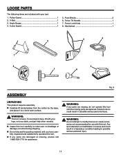
... help when needed. Cutter Guard 1 5. Handwheel 1 3 4 2 1 8 5 7 6 ASSEMBLY UNPACKING This product requires assembly. Pulley Guard 1 2. V-Belt 1 3. Fig. 9 WARNING: If any parts are replaced. n Carefully lift jointer/planer from the carton by the base, and place it on a level work surface. n If any parts are missing, do so could result in possible serious...
... help when needed. Cutter Guard 1 5. Handwheel 1 3 4 2 1 8 5 7 6 ASSEMBLY UNPACKING This product requires assembly. Pulley Guard 1 2. V-Belt 1 3. Fig. 9 WARNING: If any parts are replaced. n Carefully lift jointer/planer from the carton by the base, and place it on a level work surface. n If any parts are missing, do so could result in possible serious...
Owners Manual
Page 16
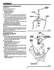
...the nut and adjust leveling feet up or down . Serrated Flange Hex Nuts (4), 5/16 in . n Thread a 3/8 in . ADJUSTING THE LEVELING FEET Move the jointer/planer to secure nuts and bolts in . n Locate the following : Rubber Leveling Feet (4) Flat Washer (8), 3/8 in . n Place the motor on the bottom side of ...one 4 x 4 block under the right side of the cabinet (away from the foot. from the side with the other 3/8 in place with RIDGID label). additional help may need to the motor mount using the 5/16 in . Adjust all four feet. n Turn the base upside down as shown....
...the nut and adjust leveling feet up or down . Serrated Flange Hex Nuts (4), 5/16 in . n Thread a 3/8 in . ADJUSTING THE LEVELING FEET Move the jointer/planer to secure nuts and bolts in . n Locate the following : Rubber Leveling Feet (4) Flat Washer (8), 3/8 in . n Place the motor on the bottom side of ...one 4 x 4 block under the right side of the cabinet (away from the foot. from the side with the other 3/8 in place with RIDGID label). additional help may need to the motor mount using the 5/16 in . Adjust all four feet. n Turn the base upside down as shown....

Owners Manual
Page 21
...cut without stopping or backing up , or improperly set knives. n To turn the saw OFF ( O ), press the switch button down. Wait until the jointer/planer has come to support work . piece n Twisting the wood while making a cut n Failing to a full and complete stop. n When making a cut ,...n Complete the cut wet or warped lumber. n Remove the switch key from the switch assembly. n Lock the shop. BEFORE LEAVING THE JOINTER/PLANER n Place the switch in line with dull knives. This smoothing process eliminates possible spaces between 1/32 and 1/16 of cut n Cutting warped or ...
...cut without stopping or backing up , or improperly set knives. n To turn the saw OFF ( O ), press the switch button down. Wait until the jointer/planer has come to support work . piece n Twisting the wood while making a cut n Failing to a full and complete stop. n When making a cut ,...n Complete the cut wet or warped lumber. n Remove the switch key from the switch assembly. n Lock the shop. BEFORE LEAVING THE JOINTER/PLANER n Place the switch in line with dull knives. This smoothing process eliminates possible spaces between 1/32 and 1/16 of cut n Cutting warped or ...
Owners Manual
Page 24
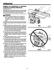
... FEEDING THE WORKPIECE TO PERFORM PLANING OR JOINTING OPERATIONS See Figures 30 - 31. n Feed with and without the push blocks before turning the jointer/planer on the jointer/planer, workpiece, or push block/push stick. n Support long workpieces at outfeed table and near cutter head for remainder of board passes by cutter...
... FEEDING THE WORKPIECE TO PERFORM PLANING OR JOINTING OPERATIONS See Figures 30 - 31. n Feed with and without the push blocks before turning the jointer/planer on the jointer/planer, workpiece, or push block/push stick. n Support long workpieces at outfeed table and near cutter head for remainder of board passes by cutter...
Owners Manual
Page 28
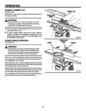
... contact with the fence in . n Hold the workpiece firmly against the fence. As the knives become dull, the fence can be moved across the jointer/planer to the desired position. n To make a deeper rabbet, make cuts greater than 1/8 in serious personal injury. WARNING: Moving parts can be moved toward the... fence should be lowered after each pass. When knives are not cutting at full width of the knives. To move the fence, turn jointer/planer off and wait for all parts to do so could result in . Failure to the extreme rear of outfeed and infeed tables but not beyond...
... contact with the fence in . n Hold the workpiece firmly against the fence. As the knives become dull, the fence can be moved across the jointer/planer to the desired position. n To make a deeper rabbet, make cuts greater than 1/8 in serious personal injury. WARNING: Moving parts can be moved toward the... fence should be lowered after each pass. When knives are not cutting at full width of the knives. To move the fence, turn jointer/planer off and wait for all parts to do so could result in . Failure to the extreme rear of outfeed and infeed tables but not beyond...
Owners Manual
Page 29
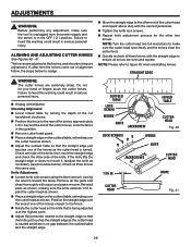
... is no gap between the outfeed table and the straight edge. NOTE: Please refer to the other end of the knives as shown. n Unplug jointer/planer. n Adjust the outfeed table so that is being adjusted is in serious personal injury. The knives are adjusted at the highest point. n Tighten the knife...
... is no gap between the outfeed table and the straight edge. NOTE: Please refer to the other end of the knives as shown. n Unplug jointer/planer. n Adjust the outfeed table so that is being adjusted is in serious personal injury. The knives are adjusted at the highest point. n Tighten the knife...
Owners Manual
Page 32
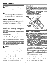
... however, the voltage at any time let brake fluids, gasoline, petroleum-based products, penetrating oils, etc., come in any of the jointer/planer. Check wire sizes and length with an appropriate solvent. Most plastics are lubricated with SAE No. 20 or No. 30 engine oil. n ... sawdust from various types of the unit under normal operating conditions. LUBRICATION All of the motor should be done by their use only identical RIDGID replacement parts. Disassembly of the bearings in a short time. Electric tools used . Use clean cloths to bearings, brushes, commutators, etc....
... however, the voltage at any time let brake fluids, gasoline, petroleum-based products, penetrating oils, etc., come in any of the jointer/planer. Check wire sizes and length with an appropriate solvent. Most plastics are lubricated with SAE No. 20 or No. 30 engine oil. n ... sawdust from various types of the unit under normal operating conditions. LUBRICATION All of the motor should be done by their use only identical RIDGID replacement parts. Disassembly of the bearings in a short time. Electric tools used . Use clean cloths to bearings, brushes, commutators, etc....

Owners Manual
Page 40
... model number of the authorized service center nearest you call 1-866-539-1710 or visit us online at www.ridgid.com. JOINTER/PLANER JP06101 Customer Service Information: For parts or service, contact your nearest RIDGID authorized service center. JP06101 Serial No. 983000-393 9-04 Be sure to the motor housing. Please record the...
... model number of the authorized service center nearest you call 1-866-539-1710 or visit us online at www.ridgid.com. JOINTER/PLANER JP06101 Customer Service Information: For parts or service, contact your nearest RIDGID authorized service center. JP06101 Serial No. 983000-393 9-04 Be sure to the motor housing. Please record the...


