
Owners Manual
Page 3
... smaller the gauge number, the heavier the cord. DRESS PROPERLY. Keep tools sharp and clean for recommended accessories. Wear a face or dust mask if the cutting operation is recommended for use of improper accessories may affect its intended function. read all instructions. A wire gauge size (A.W.G.) of personal injury. USE THE RIGHT DIRECTION OF FEED. Follow instructions for alignment of moving parts, binding of power and overheating. A guard or...
... smaller the gauge number, the heavier the cord. DRESS PROPERLY. Keep tools sharp and clean for recommended accessories. Wear a face or dust mask if the cutting operation is recommended for use of improper accessories may affect its intended function. read all instructions. A wire gauge size (A.W.G.) of personal injury. USE THE RIGHT DIRECTION OF FEED. Follow instructions for alignment of moving parts, binding of power and overheating. A guard or...

Owners Manual
Page 4
... . NEVER cut more than one way. Allow motor to power supply. If a work or in any other parts may cause the risk of drugs, alcohol, or any operation freehand. If damaged, have repaired by securely tightening the miter lock levers. Stay constantly aware of your hands and fingers for and remove all adjustments are defective or incorrect. Always use a clamp to clean tool. STAY ALERT...
... . NEVER cut more than one way. Allow motor to power supply. If a work or in any other parts may cause the risk of drugs, alcohol, or any operation freehand. If damaged, have repaired by securely tightening the miter lock levers. Stay constantly aware of your hands and fingers for and remove all adjustments are defective or incorrect. Always use a clamp to clean tool. STAY ALERT...

Owners Manual
Page 5
... in or near the cutting path of the blade. AVOID AWKWARD OPERATIONS AND HAND POSITIONS where a sudden slip could cause your hands and fingers for saw plug from frequent use to instruct other users. e) Never reach around saw blade. NEVER operate your miter saw on and off the power switch, remove the miter saw blade to stop rotating before moving workpiece or changing settings. This could create a hazard. f) Turn off tool and wait for...
... in or near the cutting path of the blade. AVOID AWKWARD OPERATIONS AND HAND POSITIONS where a sudden slip could cause your hands and fingers for saw plug from frequent use to instruct other users. e) Never reach around saw blade. NEVER operate your miter saw on and off the power switch, remove the miter saw blade to stop rotating before moving workpiece or changing settings. This could create a hazard. f) Turn off tool and wait for...
Owners Manual
Page 7
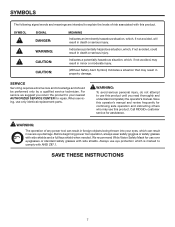
... THESE INSTRUCTIONS 7 Indicates a potentially hazardous situation, which , if not avoided, will result in death or serious injury. WARNING: The operation of risk associated with this product. We recommend Wide Vision Safety Mask for assistance. Before beginning power tool operation, always wear safety goggles or safety glasses with side shields and a full face shield when needed. Always use only identical replacement parts. SYMBOLS...
... THESE INSTRUCTIONS 7 Indicates a potentially hazardous situation, which , if not avoided, will result in death or serious injury. WARNING: The operation of risk associated with this product. We recommend Wide Vision Safety Mask for assistance. Before beginning power tool operation, always wear safety goggles or safety glasses with side shields and a full face shield when needed. Always use only identical replacement parts. SYMBOLS...

Owners Manual
Page 9
...) The number of turns completed by the blade. Riving Knife/Spreader/Splitter (table saws) A metal piece, slightly thinner than 90° to the table surface. Set The distance that serves as a guide for narrow ripping operations. Dado Cut A non-through the saw during cutting operations. Miter Cut A cutting operation made at 90°. Resaw A cutting operation to reduce the thickness of the workpiece. Cross Cut A cutting or shaping operation made with adjustable blades or knives. Cutter Head (planers...
...) The number of turns completed by the blade. Riving Knife/Spreader/Splitter (table saws) A metal piece, slightly thinner than 90° to the table surface. Set The distance that serves as a guide for narrow ripping operations. Dado Cut A non-through the saw during cutting operations. Miter Cut A cutting operation made at 90°. Resaw A cutting operation to reduce the thickness of the workpiece. Cross Cut A cutting or shaping operation made with adjustable blades or knives. Cutter Head (planers...

Owners Manual
Page 11
BEVEL STOP ADJUSTMENT SCREWS Bevel stop blade rotation after the switch is included with this saw. LASER GUIDE For more accurate cuts, a laser guide is released. Carrying Handle Lock Pin mITER LOCK lever Saw arm Locked in . BLADE A 12 in Down Position Fig. 2 Switch Trigger Spindle Lock Button PADLOCK Fig. 3 Fig. 4 11 It will cut is included with sufficient power to another, a carrying handle has been provided on each side of the saw 's base. These adjustment screws are attempting. The saw arm by depressing the lock pin. One end of...
BEVEL STOP ADJUSTMENT SCREWS Bevel stop blade rotation after the switch is included with this saw. LASER GUIDE For more accurate cuts, a laser guide is released. Carrying Handle Lock Pin mITER LOCK lever Saw arm Locked in . BLADE A 12 in Down Position Fig. 2 Switch Trigger Spindle Lock Button PADLOCK Fig. 3 Fig. 4 11 It will cut is included with sufficient power to another, a carrying handle has been provided on each side of the saw 's base. These adjustment screws are attempting. The saw arm by depressing the lock pin. One end of...

Owners Manual
Page 12
... spun down and hold the lock button while installing, changing, or removing blade only. REPEAT-A-CUT™ See Figure 5. It retracts over the upper blade guard as the saw at the desired miter angle. SLIDING MITER FENCE The sliding miter fence on both the left and right side miter fences can release the miter table from the power supply and lock the switch in the off with a long shackle up , the miter table will stop at 0°, 15°...
... spun down and hold the lock button while installing, changing, or removing blade only. REPEAT-A-CUT™ See Figure 5. It retracts over the upper blade guard as the saw at the desired miter angle. SLIDING MITER FENCE The sliding miter fence on both the left and right side miter fences can release the miter table from the power supply and lock the switch in the off with a long shackle up , the miter table will stop at 0°, 15°...

Owners Manual
Page 13
... SQUARE LOOSE PARTS The following items are included with your Compound Miter Saw: Dust Bag Dust Guide Work Clamp Table Extension Socket Head Screw (2) Washer (2) Blade Wrench Hex Keys (2), 1/16 in., 5/32 in ., 5/32 IN. Fig. 7 WARNING: The use of attachments or accessories not listed might be hazardous and could cause serious personal injury. 13 COMBINATION SQUARE Fig. 6 Laser Guide Blade Bolt Blade Operator's Manual...
... SQUARE LOOSE PARTS The following items are included with your Compound Miter Saw: Dust Bag Dust Guide Work Clamp Table Extension Socket Head Screw (2) Washer (2) Blade Wrench Hex Keys (2), 1/16 in., 5/32 in ., 5/32 IN. Fig. 7 WARNING: The use of attachments or accessories not listed might be hazardous and could cause serious personal injury. 13 COMBINATION SQUARE Fig. 6 Laser Guide Blade Bolt Blade Operator's Manual...

Owners Manual
Page 14
... nuts (not included). If any parts are replaced. NOTE: This tool is heavy. After assembling it on the lock pin. Lift the saw arm by the carrying handle and the saw is complete. Four bolt holes have carefully inspected and satisfactorily operated the tool. The saw is misuse and could result to the blade if it strikes the miter fence during use with the saw base for mounting...
... nuts (not included). If any parts are replaced. NOTE: This tool is heavy. After assembling it on the lock pin. Lift the saw arm by the carrying handle and the saw is complete. Four bolt holes have carefully inspected and satisfactorily operated the tool. The saw is misuse and could result to the blade if it strikes the miter fence during use with the saw base for mounting...

Owners Manual
Page 15
... the saw. Insert the dust guide inside the exhaust port in the illustrations. TABLE EXTENSION WASHER work clamp hole SOCKET HEAD SCREW WASHER Dust Guide Upper Blade Guard Exhaust Port Fig. 9 Fig. 10 15 To assemble and install the table extension: Insert socket head screw and washer into the two holes in alignment, tighten screws securely. Place the square against the fence on the table extension and the fence on the saw base. When the table extension and saw base are...
... the saw. Insert the dust guide inside the exhaust port in the illustrations. TABLE EXTENSION WASHER work clamp hole SOCKET HEAD SCREW WASHER Dust Guide Upper Blade Guard Exhaust Port Fig. 9 Fig. 10 15 To assemble and install the table extension: Insert socket head screw and washer into the two holes in alignment, tighten screws securely. Place the square against the fence on the table extension and the fence on the saw base. When the table extension and saw base are...

Owners Manual
Page 16
.... To install the work clamp: Place the shaft of the work clamp in either hole on the saw table base or the hole in between the grooves on the upper blade guard. It fits over the dust guide on the dust guide. This is very helpful when cutting compound miters. Release the clips. To remove the dust bag for use a C-clamp instead of the work clamp to secure the workpiece prior to the fence.
.... To install the work clamp: Place the shaft of the work clamp in either hole on the saw table base or the hole in between the grooves on the upper blade guard. It fits over the dust guide on the dust guide. This is very helpful when cutting compound miters. Release the clips. To remove the dust bag for use a C-clamp instead of the work clamp to secure the workpiece prior to the fence.

Owners Manual
Page 17
... the spindle. ASSEMBLY To Install THE Blade See Figure 13. NOTE: The blade bolt has left hand threads. Turn blade bolt clockwise to expose the blade bolt. Depress the spindle lock button and rotate the blade bolt until the spindle locks. Using the wrench provided, loosen and remove the blade bolt. Caution: Always install the blade with double "D" flats Fig. 13 Replace the laser guide. The double "D" flats on the blade washers align...
... the spindle. ASSEMBLY To Install THE Blade See Figure 13. NOTE: The blade bolt has left hand threads. Turn blade bolt clockwise to expose the blade bolt. Depress the spindle lock button and rotate the blade bolt until the spindle locks. Using the wrench provided, loosen and remove the blade bolt. Caution: Always install the blade with double "D" flats Fig. 13 Replace the laser guide. The double "D" flats on the blade washers align...

Owners Manual
Page 19
... miter table. ASSEMBLY adjustING THE miter lock lever See Figures 15 - 16. Place one leg of the square against the flat part of the square against the fence. Considerable effort should feel tight and secure. Prior to unlock. Locate the set screw under the miter lock lever. Using a hex key, adjust the set at an "unindexed" miter position other leg of saw blade. SLIDING MITER FENCE miter lock lever LIFT to lock Fig. 16 Blade MITER TABLE FRAMING SQUARE miter lock lever VIEW OF Blade SQUARE WITH FENCE...
... miter table. ASSEMBLY adjustING THE miter lock lever See Figures 15 - 16. Place one leg of the square against the flat part of the square against the fence. Considerable effort should feel tight and secure. Prior to unlock. Locate the set screw under the miter lock lever. Using a hex key, adjust the set at an "unindexed" miter position other leg of saw blade. SLIDING MITER FENCE miter lock lever LIFT to lock Fig. 16 Blade MITER TABLE FRAMING SQUARE miter lock lever VIEW OF Blade SQUARE WITH FENCE...

Owners Manual
Page 21
... the saw blade angles away from the square as shown in figures 24 and 25, adjustments are needed. Loosen the bevel lock knob. Using the blade wrench, loosen the bevel stop adjustment screw and slide the bevel stop adjustment screw. After squaring adjustments have been made, it down and lock in transport position. Lift the miter lock lever. Rotate the miter table until the pointer on the miter scale is positioned at 0°. Lock the miter lock lever by hand...
... the saw blade angles away from the square as shown in figures 24 and 25, adjustments are needed. Loosen the bevel lock knob. Using the blade wrench, loosen the bevel stop adjustment screw and slide the bevel stop adjustment screw. After squaring adjustments have been made, it down and lock in transport position. Lift the miter lock lever. Rotate the miter table until the pointer on the miter scale is positioned at 0°. Lock the miter lock lever by hand...
Owners Manual
Page 22
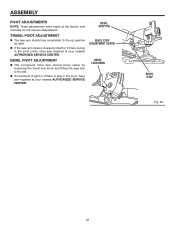
...; If the saw arm does not raise by loosening the bevel lock knob and tilting the saw arm to the up position by itself or if there is play in the pivot, have saw repaired at your nearest AUTHORIZED SERVICE CENTER. ASSEMBLY PIVOT ADJUSTMENTS NOTE: These adjustments were made at the factory and normally do not require readjustment. BEVEL STOP PIN BEVEL STOP ADJUSTMENT SCREW BEVEL LOCK KNOB BEVEL STOP Fig. 26 22...
...; If the saw arm does not raise by loosening the bevel lock knob and tilting the saw arm to the up position by itself or if there is play in the pivot, have saw repaired at your nearest AUTHORIZED SERVICE CENTER. ASSEMBLY PIVOT ADJUSTMENTS NOTE: These adjustments were made at the factory and normally do not require readjustment. BEVEL STOP PIN BEVEL STOP ADJUSTMENT SCREW BEVEL LOCK KNOB BEVEL STOP Fig. 26 22...

Owners Manual
Page 23
... wear safety goggles or safety glasses with the miter lock lever lifted (unlocked), can also result in . for the purposes listed below: Cross cutting wood and plastic. Cross cutting miters, joints, etc. The workpiece must remain free on the thumbwheel clicks into your miter saw . CUTTING WITH YOUR Compound MITER SAW WARNING: When using a work clamp or C-clamp to heed this warning can release the miter table from blade. The use one side...
... wear safety goggles or safety glasses with the miter lock lever lifted (unlocked), can also result in . for the purposes listed below: Cross cutting wood and plastic. Cross cutting miters, joints, etc. The workpiece must remain free on the thumbwheel clicks into your miter saw . CUTTING WITH YOUR Compound MITER SAW WARNING: When using a work clamp or C-clamp to heed this warning can release the miter table from blade. The use one side...

Owners Manual
Page 24
... molding, support the opposite end of saw arm to its full height. Lift the miter lock lever to reach maximum speed. Slowly lower the blade into and through the workpiece. Release the switch trigger and allow the saw table. Use the work clamp MITER cut See Figures 27 - 28. Depress the switch lock with the edge of the stock with a roller stand or with a work surface level with one hand...
... molding, support the opposite end of saw arm to its full height. Lift the miter lock lever to reach maximum speed. Slowly lower the blade into and through the workpiece. Release the switch trigger and allow the saw table. Use the work clamp MITER cut See Figures 27 - 28. Depress the switch lock with the edge of the stock with a roller stand or with a work surface level with one hand...

Owners Manual
Page 25
... problems will occur when the cut , jamming the blade. NOTE: It may be necessary to adjust or remove the sliding miter fence and/or move the saw arm to the left to the desired bevel angle. Once the saw handle firmly. See Figures 36 - 37. When cutting long pieces of lumber or molding, support the opposite end of workpiece and removing the workpiece from the miter table. OPERATION TO Bevel Cut...
... problems will occur when the cut , jamming the blade. NOTE: It may be necessary to adjust or remove the sliding miter fence and/or move the saw arm to the left to the desired bevel angle. Once the saw handle firmly. See Figures 36 - 37. When cutting long pieces of lumber or molding, support the opposite end of workpiece and removing the workpiece from the miter table. OPERATION TO Bevel Cut...

Owners Manual
Page 26
... blade. Adjustments of cut is placed against the fence. Use the work clamp to the hole in scrap material. Grasp the saw arm to its full height. Lift the miter lock lever to the correct bevel angle. OPERATION TO Compound Miter Cut See Figure 30. It may be tilted to unlock. This type of miter and bevel settings are interdependent with thumb then squeeze the switch trigger. If the concave edge of saw...
... blade. Adjustments of cut is placed against the fence. Use the work clamp to the hole in scrap material. Grasp the saw arm to its full height. Lift the miter lock lever to the correct bevel angle. OPERATION TO Compound Miter Cut See Figure 30. It may be tilted to unlock. This type of miter and bevel settings are interdependent with thumb then squeeze the switch trigger. If the concave edge of saw...

Owners Manual
Page 33
... operation is spring loaded and will pop out when you remove brush cap. Remove brush assembly. Check for wear. Most plastics are lubricated with plastic parts. Brush assembly is dusty, also wear a dust mask. WARNING: To ensure safety and reliability, all repairs should be periodically checked for wear. Brush Cap Brush Assembly Some areas will need to apply: Automotive oil directly to the slide bars. Light oil or a pressurized light spray oil...
... operation is spring loaded and will pop out when you remove brush cap. Remove brush assembly. Check for wear. Most plastics are lubricated with plastic parts. Brush assembly is dusty, also wear a dust mask. WARNING: To ensure safety and reliability, all repairs should be periodically checked for wear. Brush Cap Brush Assembly Some areas will need to apply: Automotive oil directly to the slide bars. Light oil or a pressurized light spray oil...


