Warranty
Page 1
...; Customer instruction/education • Installation • Set up to five (5) pixel failures throughout the display. (Pixel based displays may contain a limited number of pixels that may diagnose and correct the issue over the phone. REPAIR REPLACEMENT AS PROVIDED UNDER THIS WARRANTY IS YOUR EXCLUSIVE REMEDY FOR BREACH OF WARRANTY. Products and parts replaced under this warranty become the property of Rocketfish and...
...; Customer instruction/education • Installation • Set up to five (5) pixel failures throughout the display. (Pixel based displays may contain a limited number of pixels that may diagnose and correct the issue over the phone. REPAIR REPLACEMENT AS PROVIDED UNDER THIS WARRANTY IS YOUR EXCLUSIVE REMEDY FOR BREACH OF WARRANTY. Products and parts replaced under this warranty become the property of Rocketfish and...
User Manual
Page 1
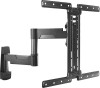
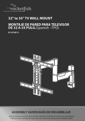
FPO) RF-HTMF19 ASSEMBLY GUIDE/GUÍA DE ENSAMBLAJE Before using your new product, please read these instructions to 55" TV WALL MOUNT MONTAJE DE PARED PARA TELEVISOR DE 32 A 55 PULG.(Spanish - 32" to prevent any damage. Antes de usar su producto nuevo, lea este instructivo para prevenir cualquier daño.
FPO) RF-HTMF19 ASSEMBLY GUIDE/GUÍA DE ENSAMBLAJE Before using your new product, please read these instructions to 55" TV WALL MOUNT MONTAJE DE PARED PARA TELEVISOR DE 32 A 55 PULG.(Spanish - 32" to prevent any damage. Antes de usar su producto nuevo, lea este instructivo para prevenir cualquier daño.

User Manual
Page 3
RF-HTMF19 ENGLISH Introduction Congratulations on your TV and accessories must be capable of supporting five times the weight of the TV and mount combined. • Do not use this product for any purpose not explicitly specified by the manufacturer. • The manufacturer is not responsible for damage or injury caused by incorrect installation or use . • Improper installation may cause...
RF-HTMF19 ENGLISH Introduction Congratulations on your TV and accessories must be capable of supporting five times the weight of the TV and mount combined. • Do not use this product for any purpose not explicitly specified by the manufacturer. • The manufacturer is not responsible for damage or injury caused by incorrect installation or use . • Improper installation may cause...

User Manual
Page 5
Tools needed You need the following tools to assemble your new TV wall mount: RF-HTMF19 Tape measure Pencil Level Drill Phillips screwdriver Socket wrench with 1/2" (13 mm) socket or adjustable wrench Tape Wood Stud Wall Concrete or Concrete Block Wall Edge-to-edge 7/32" (5.5 mm) stud finder wood drill bit Awl Hammer 3/8" (10 mm) masonry drill bit 5
Tools needed You need the following tools to assemble your new TV wall mount: RF-HTMF19 Tape measure Pencil Level Drill Phillips screwdriver Socket wrench with 1/2" (13 mm) socket or adjustable wrench Tape Wood Stud Wall Concrete or Concrete Block Wall Edge-to-edge 7/32" (5.5 mm) stud finder wood drill bit Awl Hammer 3/8" (10 mm) masonry drill bit 5

User Manual
Page 7
M4 × 12 mm screw 02 M4 × 35 mm screw M6 × 12 mm screw M6 × 20 mm screw 03 01 M6 × 35 mm screw 4 M8 × 16 mm screw 06 Hardware # M4 washer 4 M6/M8 washer 4 Spacer (2.5 mm) 4 Spacer (5 mm) 4 Spacer (22 mm) 4 TV bracket screw M5 × 8.5 mm 4 M8 × 25 mm screw M8 × 35 mm screw M8 × 50 mm screw 09 2 Lag screw 5/16 × 2 3/4 in. 10 Washer 5/16 in. 2 Locking screw 11 M5 x 6 mm 1 7 Hardware # Lbl. RF-HTMF19 TV Hardware Lbl.
M4 × 12 mm screw 02 M4 × 35 mm screw M6 × 12 mm screw M6 × 20 mm screw 03 01 M6 × 35 mm screw 4 M8 × 16 mm screw 06 Hardware # M4 washer 4 M6/M8 washer 4 Spacer (2.5 mm) 4 Spacer (5 mm) 4 Spacer (22 mm) 4 TV bracket screw M5 × 8.5 mm 4 M8 × 25 mm screw M8 × 35 mm screw M8 × 50 mm screw 09 2 Lag screw 5/16 × 2 3/4 in. 10 Washer 5/16 in. 2 Locking screw 11 M5 x 6 mm 1 7 Hardware # Lbl. RF-HTMF19 TV Hardware Lbl.

User Manual
Page 8
Hardware # C1 Concrete anchors (Fischer UX10 x 60R) 2 8 Concrete Installation Kit CMK1 (not included) Contact customer service at 1-800-620-2790 to have these additional parts shipped directly to you. Lbl.
Hardware # C1 Concrete anchors (Fischer UX10 x 60R) 2 8 Concrete Installation Kit CMK1 (not included) Contact customer service at 1-800-620-2790 to have these additional parts shipped directly to you. Lbl.

User Manual
Page 9
...; Irregularly-shaped back: There is a gap between the brackets and some part of the back of your TV and do not need spacers when assembling the wall mount. • Obstructed back: The brackets block any of the jacks on your TV. 5 Identify which type of back your TV has: ... TV has a flat, irregular, or obstructed back 1 Carefully place your TV face-down on a cushioned, clean surface to protect the screen from damages and scratches. 2 If your TV. You need 2.5 mm, 5 mm, or 22 mm spacers (03) when assembling the wall mount. 6 Remove the brackets. 9 RF-HTMF19 Installation instructions STEP 1 -
...; Irregularly-shaped back: There is a gap between the brackets and some part of the back of your TV and do not need spacers when assembling the wall mount. • Obstructed back: The brackets block any of the jacks on your TV. 5 Identify which type of back your TV has: ... TV has a flat, irregular, or obstructed back 1 Carefully place your TV face-down on a cushioned, clean surface to protect the screen from damages and scratches. 2 If your TV. You need 2.5 mm, 5 mm, or 22 mm spacers (03) when assembling the wall mount. 6 Remove the brackets. 9 RF-HTMF19 Installation instructions STEP 1 -

User Manual
Page 11
... on the back of your TV CAUTION: To avoid personal injury or property damage, do not use power tools. 1 Align the holes you determined that you selected in STEP 2 (01) through the washers. RF-HTMF19 STEP 3 - You'll need OR OR OR OR OR OR 01 Screws (4) 02 Washers (4) 04 Horizontal TV brackets (2) Phillips screwdriver...
... on the back of your TV CAUTION: To avoid personal injury or property damage, do not use power tools. 1 Align the holes you determined that you selected in STEP 2 (01) through the washers. RF-HTMF19 STEP 3 - You'll need OR OR OR OR OR OR 01 Screws (4) 02 Washers (4) 04 Horizontal TV brackets (2) Phillips screwdriver...

User Manual
Page 13
...center of the Vertical TV bracket and the center point of your holes, visit our online height-finder at: http://bestbuy.selectionassistant.com/heightfinder/#!step1 The center of the TV arm assembly ... detailed information on all TVs. When the center slot of the Vertical TV bracket is HIGHER than the center of the screen from the ground). Determine the wall-mount location ...used, the top hole in the TV arm assembly will need to 60 inches from a seated position (normally, 40 to account for the location of the VESA when determining the height of the Vertical TV bracket (05). RF-HTMF19...
...center of the Vertical TV bracket and the center point of your holes, visit our online height-finder at: http://bestbuy.selectionassistant.com/heightfinder/#!step1 The center of the TV arm assembly ... detailed information on all TVs. When the center slot of the Vertical TV bracket is HIGHER than the center of the screen from the ground). Determine the wall-mount location ...used, the top hole in the TV arm assembly will need to 60 inches from a seated position (normally, 40 to account for the location of the VESA when determining the height of the Vertical TV bracket (05). RF-HTMF19...

User Manual
Page 14
You'll need 7/32" wood drill bit 07 Mounting template 08 TV arm assembly 1/2" socket wrench Level 09 Lag screw (2) 10 Washer (2) Awl Drill Tape Edge-to -edge stud finder or an awl. Caution: Drywall covering the wall must not exceed 5/8 in . (3.8 × 8.9 cm). STEP 6 - Minimum wood stud size: nominal 2 × 4 in. (5.1 × 10.2 cm) actual 1 1/2 × 3 1/2 in . (1.6 cm). Option 1: Install on a wood stud wall 1 Locate the stud, then verify the center of the stud with an edge-to edge stud finder 14
You'll need 7/32" wood drill bit 07 Mounting template 08 TV arm assembly 1/2" socket wrench Level 09 Lag screw (2) 10 Washer (2) Awl Drill Tape Edge-to -edge stud finder or an awl. Caution: Drywall covering the wall must not exceed 5/8 in . (3.8 × 8.9 cm). STEP 6 - Minimum wood stud size: nominal 2 × 4 in. (5.1 × 10.2 cm) actual 1 1/2 × 3 1/2 in . (1.6 cm). Option 1: Install on a wood stud wall 1 Locate the stud, then verify the center of the stud with an edge-to edge stud finder 14

User Manual
Page 15
RF-HTMF19 2 Align the center of 2 3/4 in. (70 mm) using a 7/32 in. (5.5 mm) diameter drill bit, then remove the mounting template. (69 mm) (257.3/5/34m2inim.n(7)0 mm) 7/32 in the previous step and make sure that it is level. Tape the mounting template to the wall. 3 Drill two pilot holes through the mounting template to a depth of the mounting template (07) at the height you determined in . (5.5 mm) 4 Move the cover out away from the arm assembly wall plate. 08 15
RF-HTMF19 2 Align the center of 2 3/4 in. (70 mm) using a 7/32 in. (5.5 mm) diameter drill bit, then remove the mounting template. (69 mm) (257.3/5/34m2inim.n(7)0 mm) 7/32 in the previous step and make sure that it is level. Tape the mounting template to the wall. 3 Drill two pilot holes through the mounting template to a depth of the mounting template (07) at the height you determined in . (5.5 mm) 4 Move the cover out away from the arm assembly wall plate. 08 15

User Manual
Page 17
...Installation Kit (CMK1) is level. Tape the mounting template to the wall, then drill pilot holes to request it is not included. Mount the wall plate directly onto the concrete surface. 1 Align the center of 3 in. (76 mm) using a 3/8 in the previous step and make sure that it . 17 Minimum concrete block size...3/8 in . (20.3 cm). Contact Customer Service to a depth of the mounting template (07) at the height you determined in . (10 mm) diameter masonry drill bit, then remove the mounting template. RF-HTMF19 STEP 6 - Option 2: Install on a solid concrete or concrete block wall ...
...Installation Kit (CMK1) is level. Tape the mounting template to the wall, then drill pilot holes to request it is not included. Mount the wall plate directly onto the concrete surface. 1 Align the center of 3 in. (76 mm) using a 3/8 in the previous step and make sure that it . 17 Minimum concrete block size...3/8 in . (20.3 cm). Contact Customer Service to a depth of the mounting template (07) at the height you determined in . (10 mm) diameter masonry drill bit, then remove the mounting template. RF-HTMF19 STEP 6 - Option 2: Install on a solid concrete or concrete block wall ...

User Manual
Page 18
2 Insert the concrete wall anchors (C1) (see Concrete Installation Kit CMK1 (not included) on page 8) into the pilot holes and use a hammer to make sure that the anchors are flush with the concrete surface. C C 3 Move the wall plate cover out away from the wall plate. 18
2 Insert the concrete wall anchors (C1) (see Concrete Installation Kit CMK1 (not included) on page 8) into the pilot holes and use a hammer to make sure that the anchors are flush with the concrete surface. C C 3 Move the wall plate cover out away from the wall plate. 18

User Manual
Page 19
RF-HTMF19 4 Align the TV arm assembly (08) with the anchors (C1), insert the lag screws (09) through the washers (10) and into the holes in the wall plate, then tighten the lag screws only until they are firm against the wall plate. DO NOT over-tighten the lag screws (09). 19 CAUTION: Avoid potential injuries or property damage!
RF-HTMF19 4 Align the TV arm assembly (08) with the anchors (C1), insert the lag screws (09) through the washers (10) and into the holes in the wall plate, then tighten the lag screws only until they are firm against the wall plate. DO NOT over-tighten the lag screws (09). 19 CAUTION: Avoid potential injuries or property damage!

User Manual
Page 21
Select the height you must use the locking screw (11) to secure your TV to the TV arm assembly with the locking screw (11). You may need assistance with this step. 3 Secure your TV on the arm assembly. CAUTION: To avoid possible personal injury or equipment damage, you want by choosing the appropriate slot in the vertical TV bracket. Select the height you want HEAVY! RF-HTMF19 2 Hang your TV to the TV arm assembly. 21
Select the height you must use the locking screw (11) to secure your TV to the TV arm assembly with the locking screw (11). You may need assistance with this step. 3 Secure your TV on the arm assembly. CAUTION: To avoid possible personal injury or equipment damage, you want by choosing the appropriate slot in the vertical TV bracket. Select the height you want HEAVY! RF-HTMF19 2 Hang your TV to the TV arm assembly. 21

User Manual
Page 22
Manage cables • Fully extend the TV arm assembly (08) to provide enough slack, then route cables along the arms, inserting them into the channels on the arms to provide a clean look to prevent unwanted movement. Adjust the tilt Note: After your installation. hex key (not provided). • Loosen the tension knob with your fingers, adjust the tilt angle, then tighten the knob to keep your TV in place, tighten the tilt tension knob to your TV is in place. 08 22 Additional tension can be applied by using a 3/16 in. STEP 8 - STEP 9 -
Manage cables • Fully extend the TV arm assembly (08) to provide enough slack, then route cables along the arms, inserting them into the channels on the arms to provide a clean look to prevent unwanted movement. Adjust the tilt Note: After your installation. hex key (not provided). • Loosen the tension knob with your fingers, adjust the tilt angle, then tighten the knob to keep your TV in place, tighten the tilt tension knob to your TV is in place. 08 22 Additional tension can be applied by using a 3/16 in. STEP 8 - STEP 9 -

User Manual
Page 23
RF-HTMF19 2 Level your TV. 23 STEP 10 - Adjust the level 1 Loosen the locking screw (11) with a Phillips screwdriver.
RF-HTMF19 2 Level your TV. 23 STEP 10 - Adjust the level 1 Loosen the locking screw (11) with a Phillips screwdriver.

User Manual
Page 25
For customer service, call: 1-800-620-2790 (U.S. RF-HTMF19 08 3 Lift your TV off the arm assembly. 11 HEAVY! 2 Remove the locking screw (11) with this step. You may need assistance with a Phillips screwdriver. and Canada) 25
For customer service, call: 1-800-620-2790 (U.S. RF-HTMF19 08 3 Lift your TV off the arm assembly. 11 HEAVY! 2 Remove the locking screw (11) with this step. You may need assistance with a Phillips screwdriver. and Canada) 25

User Manual
Page 26
.... If service of Products or parts are not returned to you own your Rocketfish Product during the Warranty Period. LIFETIME LIMITED WARRANTY Definitions: The Distributor* of Rocketfish branded products warrants to you, the original purchaser of this new Rocketfish-branded product ("Product"), that the Product shall be purchased in the United States or Canada from a Best Buy online website...
.... If service of Products or parts are not returned to you own your Rocketfish Product during the Warranty Period. LIFETIME LIMITED WARRANTY Definitions: The Distributor* of Rocketfish branded products warrants to you, the original purchaser of this new Rocketfish-branded product ("Product"), that the Product shall be purchased in the United States or Canada from a Best Buy online website...

User Manual
Page 27
... the factory applied serial number has been altered or removed • Loss or Theft of this product or any part of Best Buy and its affiliated companies. *Distributed by Best Buy Purchasing, LLC 7601 Penn Ave South, Richfield, MN 55423 U.S.A. ©2022 Best Buy. REPAIR REPLACEMENT AS PROVIDED UNDER THIS WARRANTY IS YOUR EXCLUSIVE REMEDY FOR BREACH OF WARRANTY. ROCKETFISH...
... the factory applied serial number has been altered or removed • Loss or Theft of this product or any part of Best Buy and its affiliated companies. *Distributed by Best Buy Purchasing, LLC 7601 Penn Ave South, Richfield, MN 55423 U.S.A. ©2022 Best Buy. REPAIR REPLACEMENT AS PROVIDED UNDER THIS WARRANTY IS YOUR EXCLUSIVE REMEDY FOR BREACH OF WARRANTY. ROCKETFISH...

