

Operation Manual
Page 1
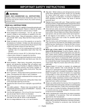
..., they are assembling parts, making adjustments, cleaning, or when not in the presence of a source of possible hazards when not using only identical replacement parts. Exposure to drain the battery pack completely before storing the device. When battery becomes fully charged, unplug the charger from the power supply and remove the battery pack from the battery. Be aware of ignition, such as a pilot light. This...
..., they are assembling parts, making adjustments, cleaning, or when not in the presence of a source of possible hazards when not using only identical replacement parts. Exposure to drain the battery pack completely before storing the device. When battery becomes fully charged, unplug the charger from the power supply and remove the battery pack from the battery. Be aware of ignition, such as a pilot light. This...

Operation Manual
Page 2
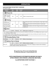
... charge level indicator button: LED FUNCTIONS CHARGE STATUS 0 - 10% 10 - 25% 25 - 50% 50 - 75% 75 - 100% CHARGING THE BATTERY PACK Battery packs are shipped in a serious burn. For warranty details go to replace the batteries. Please refer to charger operator's manual. Handling of lithium-ion batteries in fire and/or serious injury. Upon removal, cover the battery pack's terminals with metal objects and/or body parts...
... charge level indicator button: LED FUNCTIONS CHARGE STATUS 0 - 10% 10 - 25% 25 - 50% 50 - 75% 75 - 100% CHARGING THE BATTERY PACK Battery packs are shipped in a serious burn. For warranty details go to replace the batteries. Please refer to charger operator's manual. Handling of lithium-ion batteries in fire and/or serious injury. Upon removal, cover the battery pack's terminals with metal objects and/or body parts...

Operation Manual 1
Page 2
... plastic parts. Refer to them frequently and use , store, or charge battery packs or products in a risk of fire and electric shock. IMPORTANT SAFETY INSTRUCTIONS 1. Never use charger outdoors or expose to comply with a damaged cord or plug, which could result in a risk of fire, electric shock, or injury to an authorized serviceman when service or repair is properly wired and in use this...
... plastic parts. Refer to them frequently and use , store, or charge battery packs or products in a risk of fire and electric shock. IMPORTANT SAFETY INSTRUCTIONS 1. Never use charger outdoors or expose to comply with a damaged cord or plug, which could result in a risk of fire, electric shock, or injury to an authorized serviceman when service or repair is properly wired and in use this...

Operation Manual 1
Page 4
... make you should snap into your nearest repair center for electrical check. When the charger is charging. Charge time varies and is correctly connected. Connect the power adaptor to a power source, then connect the power cable to within an acceptable temperature range. All battery pack LEDs will turn off the battery pack. Remove the power adaptor from the charger, depress the latch...
... make you should snap into your nearest repair center for electrical check. When the charger is charging. Charge time varies and is correctly connected. Connect the power adaptor to a power source, then connect the power cable to within an acceptable temperature range. All battery pack LEDs will turn off the battery pack. Remove the power adaptor from the charger, depress the latch...
Operation Manual 1
Page 5
... charged. For Warranty details go to repeat the conditions a second time by removing and reinstalling the battery pack. Charging Battery Pack Fast charging OFF Flashing OFF Battery is 100% charged, the battery LEDs will remain ON for instructions). • If a different battery also indicates Error, the charger should be replaced. English BATTERY PACK RED LED GREEN ORANGE LED LED Power On ACTION Plugged into AC power supply without battery...
... charged. For Warranty details go to repeat the conditions a second time by removing and reinstalling the battery pack. Charging Battery Pack Fast charging OFF Flashing OFF Battery is 100% charged, the battery LEDs will remain ON for instructions). • If a different battery also indicates Error, the charger should be replaced. English BATTERY PACK RED LED GREEN ORANGE LED LED Power On ACTION Plugged into AC power supply without battery...
Operation Manual 2
Page 6
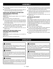
...; Maintain lawn mower with local codes for proper operation and installation of lower end until the blade comes to a complete stop, and remove the start key installed. Keep hands and feet away from cutting area. A moment of grass and leaves on slippery surfaces. Replace damaged or unevenly worn blades before performing any maintenance, cleaning the lawn mower, removing the grass catcher, or removing the mulching plug. Never use common sense when operating the lawn mower. Mower blades are...
...; Maintain lawn mower with local codes for proper operation and installation of lower end until the blade comes to a complete stop, and remove the start key installed. Keep hands and feet away from cutting area. A moment of grass and leaves on slippery surfaces. Replace damaged or unevenly worn blades before performing any maintenance, cleaning the lawn mower, removing the grass catcher, or removing the mulching plug. Never use common sense when operating the lawn mower. Mower blades are...

Operation Manual 2
Page 7
... specified in the instructions for the cause. Avoid discharging material against a wall or obstruction, which can be performed by the lawn mower blade can make sure the new grass catcher meets original manufacturer's recommendations and specifications. Use only authorized replacement parts when servicing the product. Vibration is shut off -position before storing, servicing, or changing accessories such as rocks, tree nuts, sticks, metal, wire, bones, toys...
... specified in the instructions for the cause. Avoid discharging material against a wall or obstruction, which can be performed by the lawn mower blade can make sure the new grass catcher meets original manufacturer's recommendations and specifications. Use only authorized replacement parts when servicing the product. Vibration is shut off -position before storing, servicing, or changing accessories such as rocks, tree nuts, sticks, metal, wire, bones, toys...

Operation Manual 2
Page 8
... them frequently and use , mower should also be plugged into an electrical outlet; IMPORTANT SAFETY INSTRUCTIONS Battery tools do not have to be removed and stored in a separate location out of the reach of children. Do not charge battery tool in a damp or wet location. When not in use them these instructions. therefore, they are familiar with the instructions, to operate this product only...
... them frequently and use , mower should also be plugged into an electrical outlet; IMPORTANT SAFETY INSTRUCTIONS Battery tools do not have to be removed and stored in a separate location out of the reach of children. Do not charge battery tool in a damp or wet location. When not in use them these instructions. therefore, they are familiar with the instructions, to operate this product only...
Operation Manual 2
Page 9
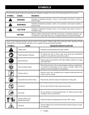
...levels of injury, user must read and understand operator's manual before using this product. Do not operate on wet ground. SYMBOL NAME DESIGNATION/EXPLANATION Safety Alert Indicates a potential personal injury hazard. Close cover during use in dry conditions and to comply with this product. Thrown objects can result in electric... battery, battery compartment, or electronic components to a potential injury (e.g. Do not operate on inclines greater than 15º. No Reach No Slope Keep Children and Bystanders Away Ricochet Do not reach hands or feet under mower deck....
...levels of injury, user must read and understand operator's manual before using this product. Do not operate on wet ground. SYMBOL NAME DESIGNATION/EXPLANATION Safety Alert Indicates a potential personal injury hazard. Close cover during use in dry conditions and to comply with this product. Thrown objects can result in electric... battery, battery compartment, or electronic components to a potential injury (e.g. Do not operate on inclines greater than 15º. No Reach No Slope Keep Children and Bystanders Away Ricochet Do not reach hands or feet under mower deck....
Operation Manual 2
Page 11
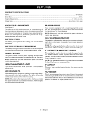
... project you . NOTE: Mower will not start levers inside the upper handle are squeezed after. START BUTTON AND START LEVERS The start button and the start without the grass catcher or mulch plug attached. FEATURES PRODUCT SPECIFICATIONS Motor...40 Volt DC Deck Size...20 in . to start without the grass catcher or mulch plug attached. rear KNOW YOUR LAWN MOWER See Figure 1. HEIGHT ADJUSTMENT LEVER The height adjustment lever provides cutting height adjustments. NOTE: Mower will not start the blades. It will also start if the start key must be inserted...
... project you . NOTE: Mower will not start levers inside the upper handle are squeezed after. START BUTTON AND START LEVERS The start button and the start without the grass catcher or mulch plug attached. FEATURES PRODUCT SPECIFICATIONS Motor...40 Volt DC Deck Size...20 in . to start without the grass catcher or mulch plug attached. rear KNOW YOUR LAWN MOWER See Figure 1. HEIGHT ADJUSTMENT LEVER The height adjustment lever provides cutting height adjustments. NOTE: Mower will not start the blades. It will also start if the start key must be inserted...

Operation Manual 2
Page 12
... raising the handle. WARNING: To prevent accidental starting of the mower during shipping. Accidental starting , do not operate this product. When installing, allow the starter cable to comply could result in place. 8 - Make sure that may have carefully inspected and satisfactorily operated the product. n If any adjustments or installations with this product until the parts are included. PACKING LIST Lawn Mower Start Key Grass Catcher Bag and Frame Mulching Plug Operator's Manual WARNING: If...
... raising the handle. WARNING: To prevent accidental starting of the mower during shipping. Accidental starting , do not operate this product. When installing, allow the starter cable to comply could result in place. 8 - Make sure that may have carefully inspected and satisfactorily operated the product. n If any adjustments or installations with this product until the parts are included. PACKING LIST Lawn Mower Start Key Grass Catcher Bag and Frame Mulching Plug Operator's Manual WARNING: If...
Operation Manual 2
Page 13
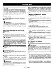
...; Reinstall the start key and battery pack when you are ready to mow. The use . INSTALLING THE GRASS CATCHER (FOR REAR BAGGING OPERATION) See Figures 6 - 7. WARNING: Always inspect mower for missing or damaged parts and blade for your lawn. Following these instructions will not start if the metal locks are not fully seated. Reinstall the start key and battery pack when you are ready to a low-cutting position. SETTING BLADE HEIGHT See Figure...
...; Reinstall the start key and battery pack when you are ready to mow. The use . INSTALLING THE GRASS CATCHER (FOR REAR BAGGING OPERATION) See Figures 6 - 7. WARNING: Always inspect mower for missing or damaged parts and blade for your lawn. Following these instructions will not start if the metal locks are not fully seated. Reinstall the start key and battery pack when you are ready to a low-cutting position. SETTING BLADE HEIGHT See Figure...
Operation Manual 2
Page 14
... your battery, or to mow. English Tighten securely all fasteners and caps and do not operate this product for the purpose listed below: Mowing your lawn WARNING: With the exception of using the self-propelled feature to relocate the mower to the mowing site, always remove battery packs and start button is securely closed. SELF-PROPELLED MOWING See Figure 13. INSTALLING/REMOVING BATTERY PACK See Figure 10. Raise the battery cover. ...
... your battery, or to mow. English Tighten securely all fasteners and caps and do not operate this product for the purpose listed below: Mowing your lawn WARNING: With the exception of using the self-propelled feature to relocate the mower to the mowing site, always remove battery packs and start button is securely closed. SELF-PROPELLED MOWING See Figure 13. INSTALLING/REMOVING BATTERY PACK See Figure 10. Raise the battery cover. ...
Operation Manual 2
Page 15
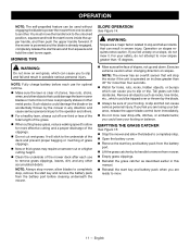
... stick to the underside of the deck and prevent proper bagging or mulching of grass clippings. New or thick grass may require a narrower cut wet grass. EMPTYING THE GRASS CATCHER See Figure 15. Stop the mower and allow the blades to completely stop , remove the start levers again. OPERATION NOTE: The self-propelled feature can be used without engaging the blade to power the mower from one -third or less of...
... stick to the underside of the deck and prevent proper bagging or mulching of grass clippings. New or thick grass may require a narrower cut wet grass. EMPTYING THE GRASS CATCHER See Figure 15. Stop the mower and allow the blades to completely stop , remove the start levers again. OPERATION NOTE: The self-propelled feature can be used without engaging the blade to power the mower from one -third or less of...

Operation Manual 2
Page 16
... the mower housing and/or underneath the mower deck. GENERAL MAINTENANCE Avoid using a torque wrench (not provided) to ensure the bolt is 310 - 360 in a short circuit, increased risk of any time let brake fluids, gasoline, petroleumbased products, penetrating oils, etc., come to a complete stop and the batteries and start key. REPLACING THE CUTTING BLADE See Figures 16 - 17. The recommended torque for damaged, missing, or loose parts such...
... the mower housing and/or underneath the mower deck. GENERAL MAINTENANCE Avoid using a torque wrench (not provided) to ensure the bolt is 310 - 360 in a short circuit, increased risk of any time let brake fluids, gasoline, petroleumbased products, penetrating oils, etc., come to a complete stop and the batteries and start key. REPLACING THE CUTTING BLADE See Figures 16 - 17. The recommended torque for damaged, missing, or loose parts such...
Operation Manual 2
Page 17
... - 19. Check blade for damage, breakage, and wear. NOTICE: Do not allow the starter cable to the torque specifications above. Failure to properly attach the blade could cause it to the standing position. Have repairs made on its side and clean grass clippings that have accumulated on the handle adjustment knobs are fully locked before attempting to raise the mower to come loose and...
... - 19. Check blade for damage, breakage, and wear. NOTICE: Do not allow the starter cable to the torque specifications above. Failure to properly attach the blade could cause it to the standing position. Have repairs made on its side and clean grass clippings that have accumulated on the handle adjustment knobs are fully locked before attempting to raise the mower to come loose and...

Operation Manual 2
Page 18
.... Check that grass catcher, mulch plug, charge accessory not installed correctly. properly. Grass blocking rear chute of the deck. Remove grass catcher bag and remove the blockage. Have repaired by an authorized service center before m owing. English Handle assembly is unbalanced, excessively or Replace the blade. or side discharge accessory is installed correctly. Mower hard to ensure your complete satisfaction. Mower vibrating at higher speed. Stop the motor, remove start key, and battery. Stop the motor, remove start key, and battery. Raise the cutting...
.... Check that grass catcher, mulch plug, charge accessory not installed correctly. properly. Grass blocking rear chute of the deck. Remove grass catcher bag and remove the blockage. Have repaired by an authorized service center before m owing. English Handle assembly is unbalanced, excessively or Replace the blade. or side discharge accessory is installed correctly. Mower hard to ensure your complete satisfaction. Mower vibrating at higher speed. Stop the motor, remove start key, and battery. Stop the motor, remove start key, and battery. Raise the cutting...
Parts Diagram
Page 3
... 2 Battery Hold Assembly 1 Starting Instructions Label 1 Handles Fully Extended Label.......... 1 Mulch Plug Hangtag 1 Start Key Hangtag 1 20 in all correspondence regarding your LAWN MOWER or when ordering replacement parts. Key No. 60 1 Trigger Assembly 1 Upper Handle Tube Assembly (Inc. Always mention the model number in . Key Nos. 28-30, 36-38, 62-66, 80 & 124-125 1 Grass Bag Sensor Switch 1 Screw w/Washer (M4 x 10 mm, T20 Torx Pan Hd 1 Dust Proof Plate 1 Lift Arm Bracket...
... 2 Battery Hold Assembly 1 Starting Instructions Label 1 Handles Fully Extended Label.......... 1 Mulch Plug Hangtag 1 Start Key Hangtag 1 20 in all correspondence regarding your LAWN MOWER or when ordering replacement parts. Key No. 60 1 Trigger Assembly 1 Upper Handle Tube Assembly (Inc. Always mention the model number in . Key Nos. 28-30, 36-38, 62-66, 80 & 124-125 1 Grass Bag Sensor Switch 1 Screw w/Washer (M4 x 10 mm, T20 Torx Pan Hd 1 Dust Proof Plate 1 Lift Arm Bracket...

Parts Diagram
Page 4
... 1 Motor Fan Blade Adapter 1 Hex Nut (M10 1 20 in . Wheel Assembly 2 Hub Cap 4 Flange Lock Nut (#3/8-16 UNC)....... 2 Rear Axle w/Rotation Plate 1 Operator's Manual 4 RYOBI 40V LAWN MOWER − MODEL NO. Grass Bag 1 Mulch Plug Assembly (Inc. NUMBER Inner Wire w/Connector Between Transmission & PCBA 1 Spacer 1 Height Adjustment Handle 1 Screw (M3 x 9 mm, Flat Hd 2 Screw (M8 x 45 mm, T40 Torx Pan Hd.)....... 2 Momentary Switch 1 Switch w/Terminals 2 Compression Spring 2 Guide Tube 2 Blade Button 1 Compression Spring 2 Push Button 2 Main Warning Label (Part 1 1 Screw...
... 1 Motor Fan Blade Adapter 1 Hex Nut (M10 1 20 in . Wheel Assembly 2 Hub Cap 4 Flange Lock Nut (#3/8-16 UNC)....... 2 Rear Axle w/Rotation Plate 1 Operator's Manual 4 RYOBI 40V LAWN MOWER − MODEL NO. Grass Bag 1 Mulch Plug Assembly (Inc. NUMBER Inner Wire w/Connector Between Transmission & PCBA 1 Spacer 1 Height Adjustment Handle 1 Screw (M3 x 9 mm, Flat Hd 2 Screw (M8 x 45 mm, T40 Torx Pan Hd.)....... 2 Momentary Switch 1 Switch w/Terminals 2 Compression Spring 2 Guide Tube 2 Blade Button 1 Compression Spring 2 Push Button 2 Main Warning Label (Part 1 1 Screw...

Parts Diagram
Page 5
RYOBI 40V LAWN MOWER − MODEL NO. RY40LM03 SWITCH SWITCH BLUE SWITCH GREEN BLUE SWITCH BLUE SPEED SWITCH BROWN LED DRIVE MOTOR CONTROLLER BLADE MOTOR CONTROLLER BAG SENSOR CONTACT PLATE ASSEMBLY START KEY TERMINAL RED BLACK PINK (DUAL DISCHARGE WIRE) BLACK TRANSMISSION ASSEMBLY RED TILT SENSOR BLACK MOTOR ORANGE WIRING DIAGRAM 5
RYOBI 40V LAWN MOWER − MODEL NO. RY40LM03 SWITCH SWITCH BLUE SWITCH GREEN BLUE SWITCH BLUE SPEED SWITCH BROWN LED DRIVE MOTOR CONTROLLER BLADE MOTOR CONTROLLER BAG SENSOR CONTACT PLATE ASSEMBLY START KEY TERMINAL RED BLACK PINK (DUAL DISCHARGE WIRE) BLACK TRANSMISSION ASSEMBLY RED TILT SENSOR BLACK MOTOR ORANGE WIRING DIAGRAM 5


