

User Manual Ver.1.0 (English)
Page 1
User manual S19C150N S19C150F S20C150FL S22C150N The color and the appearance may differ depending on the product, and the specifications are subject to change without prior notice to improve the performance. BN46-00338B-01
User manual S19C150N S19C150F S20C150FL S22C150N The color and the appearance may differ depending on the product, and the specifications are subject to change without prior notice to improve the performance. BN46-00338B-01

User Manual Ver.1.0 (English)
Page 2
... the Packaging Checking the Components Parts Frontal Button Reverse Side Installation Attaching the Stand (S19C150F / S20C150FL) Attaching the Stand (S19C150N / S22C150N) Removing the Stand (S19C150F / S20C150FL) Removing the Stand (S19C150N / S22C150N) Installing a Wall-mount Kit or Desktop Stand (S19C150F / S20C150FL) Adjusting the Product Tilt Anti-theft Lock Before Connecting Pre-connection Checkpoints Connecting...
... the Packaging Checking the Components Parts Frontal Button Reverse Side Installation Attaching the Stand (S19C150F / S20C150FL) Attaching the Stand (S19C150N / S22C150N) Removing the Stand (S19C150F / S20C150FL) Removing the Stand (S19C150N / S22C150N) Installing a Wall-mount Kit or Desktop Stand (S19C150F / S20C150FL) Adjusting the Product Tilt Anti-theft Lock Before Connecting Pre-connection Checkpoints Connecting...

User Manual Ver.1.0 (English)
Page 5
... Installing the Software Removing the Software Requirements Before Contacting Samsung Customer Service Center Testing the Product Checking the Resolution and Frequency Check the following. Q & A General (S19C150N / S22C150N) General (S19C150F / S20C150FL) PowerSaver Standard Signal Mode Table APPENDIX 83... 89 89 89 89 Contact SAMSUNG WORLD WIDE Responsibility for the Pay Service (Cost to Customers) Not a product defect ...
... Installing the Software Removing the Software Requirements Before Contacting Samsung Customer Service Center Testing the Product Checking the Resolution and Frequency Check the following. Q & A General (S19C150N / S22C150N) General (S19C150F / S20C150FL) PowerSaver Standard Signal Mode Table APPENDIX 83... 89 89 89 89 Contact SAMSUNG WORLD WIDE Responsibility for the Pay Service (Cost to Customers) Not a product defect ...

User Manual Ver.1.0 (English)
Page 23
S19C150F / S20C150FL S19C150N / S22C150N DC 14V RGB IN DC 14V RGB IN DC 14V RGB IN DC 14V RGB IN Port DC 14V RGB IN Description Connects to a PC using the D-SUB cable. 23 1 Preparations Specifications are subject to change without notice to improve quality. Provided ports may differ from what is shown. Connect to the DC power adapter. 1 Preparations 1.2.2 Reverse Side The color and shape of parts may vary depending on the product.
S19C150F / S20C150FL S19C150N / S22C150N DC 14V RGB IN DC 14V RGB IN DC 14V RGB IN DC 14V RGB IN Port DC 14V RGB IN Description Connects to a PC using the D-SUB cable. 23 1 Preparations Specifications are subject to change without notice to improve quality. Provided ports may differ from what is shown. Connect to the DC power adapter. 1 Preparations 1.2.2 Reverse Side The color and shape of parts may vary depending on the product.
User Manual Ver.1.0 (English)
Page 24
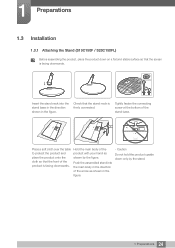
1 Preparations 1.3 Installation 1.3.1 Attaching the Stand (S19C150F / S20C150FL) Before assembling the product, place the product down only by the figure. Place a soft cloth over the table to protect the product and place ...
1 Preparations 1.3 Installation 1.3.1 Attaching the Stand (S19C150F / S20C150FL) Before assembling the product, place the product down only by the figure. Place a soft cloth over the table to protect the product and place ...
User Manual Ver.1.0 (English)
Page 26
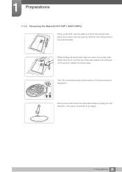
Remove the stand neck from the stand base by pulling it . While holding the stand neck with one hand, pound the other fisted hand down onto the top of the stand base in the direction of the stand base to detach the stand base. Turn the connecting screw at the bottom of the arrow to separate it in the direction of the product faces downwards. 1 Preparations 1.3.3 Removing the Stand (S19C150F / S20C150FL) Place a soft cloth over the table to protect the product and place the product onto the cloth so that the front of the arrow as shown in the figure. 26 1 Preparations
Remove the stand neck from the stand base by pulling it . While holding the stand neck with one hand, pound the other fisted hand down onto the top of the stand base in the direction of the stand base to detach the stand base. Turn the connecting screw at the bottom of the arrow to separate it in the direction of the product faces downwards. 1 Preparations 1.3.3 Removing the Stand (S19C150F / S20C150FL) Place a soft cloth over the table to protect the product and place the product onto the cloth so that the front of the arrow as shown in the figure. 26 1 Preparations

User Manual Ver.1.0 (English)
Page 28
...a wall mount, disconnect the stand base from the wall. Be sure to attach. Samsung shall not be held liable for any damage or injury caused by using excessive force. 1 Preparations 1.3.5 Installing a Wall-mount Kit or Desktop Stand (S19C150F / S20C150FL) 1 2 A A 3 4 B Attach the wall-mount kit or desktop stand ...damage or personal injury caused by using improper screws or attaching the wall-mount kit or desktop stand using excessive force. Samsung shall not be held liable for a wall mount that does not comply with the VESA standards may get damaged or fall and ...
...a wall mount, disconnect the stand base from the wall. Be sure to attach. Samsung shall not be held liable for any damage or injury caused by using excessive force. 1 Preparations 1.3.5 Installing a Wall-mount Kit or Desktop Stand (S19C150F / S20C150FL) 1 2 A A 3 4 B Attach the wall-mount kit or desktop stand ...damage or personal injury caused by using improper screws or attaching the wall-mount kit or desktop stand using excessive force. Samsung shall not be held liable for a wall mount that does not comply with the VESA standards may get damaged or fall and ...

User Manual Ver.1.0 (English)
Page 29
Specifications are subject to change without notice to improve quality. S19C150F / S20C150FL 0° (±2°) ~ 20° (±2°) S19C150N / S22C150N 0° (±2°) ~ 20° (±2°) You can adjust the tilt of your monitor. Hold the lower part of parts may differ from what is shown. 1 Preparations 1.3.6 Adjusting the Product Tilt The color and shape of the product and adjust the tilt carefully. 29 1 Preparations
Specifications are subject to change without notice to improve quality. S19C150F / S20C150FL 0° (±2°) ~ 20° (±2°) S19C150N / S22C150N 0° (±2°) ~ 20° (±2°) You can adjust the tilt of your monitor. Hold the lower part of parts may differ from what is shown. 1 Preparations 1.3.6 Adjusting the Product Tilt The color and shape of the product and adjust the tilt carefully. 29 1 Preparations

User Manual Ver.1.0 (English)
Page 30
Refer to improve quality. S19C150F / S20C150FL S19C150N / S22C150N DC 14V RGB IN The color and shape of the display. 4 Lock the locking device. An anti-theft locking device can ...
Refer to improve quality. S19C150F / S20C150FL S19C150N / S22C150N DC 14V RGB IN The color and shape of the display. 4 Lock the locking device. An anti-theft locking device can ...

User Manual Ver.1.0 (English)
Page 31
... back of ports on source devices may differ from device to connect. 31 2 Connecting and Using a Source Device 2 Connecting and Using a Source Device 2.1 Before Connecting S19C150F / S20C150FL S19C150N / S22C150N DC 14V RGB IN 2.1.1 Pre-connection Checkpoints Before connecting a source device, read the user manual provided with it.
... back of ports on source devices may differ from device to connect. 31 2 Connecting and Using a Source Device 2 Connecting and Using a Source Device 2.1 Before Connecting S19C150F / S20C150FL S19C150N / S22C150N DC 14V RGB IN 2.1.1 Pre-connection Checkpoints Before connecting a source device, read the user manual provided with it.

User Manual Ver.1.0 (English)
Page 32
2 Connecting and Using a Source Device 2.2 Connecting the Power Connect the power adapter to the product. Next, connect the DC power adapter to [DC 14V] jack on the rear of the product. Plug in the power cable to the DC power adapter. S19C150F / S20C150FL DC 14V S19C150N / S22C150N DC 14V The input voltage is switched automatically. 32 2 Connecting and Using a Source Device Connect the power cable to the power socket.
2 Connecting and Using a Source Device 2.2 Connecting the Power Connect the power adapter to the product. Next, connect the DC power adapter to [DC 14V] jack on the rear of the product. Plug in the power cable to the DC power adapter. S19C150F / S20C150FL DC 14V S19C150N / S22C150N DC 14V The input voltage is switched automatically. 32 2 Connecting and Using a Source Device Connect the power cable to the power socket.

User Manual Ver.1.0 (English)
Page 33
... connect the power cable before connecting the power cable. 2 Connecting and Using a Source Device 2.3 Connecting and Using a PC Select a connection method suitable for your PC. S19C150F / S20C150FL RGB IN 1 Connect the D-SUB cable to the product and a power socket. Next, turn on the power switch on the PC. (For details, refer...
... connect the power cable before connecting the power cable. 2 Connecting and Using a Source Device 2.3 Connecting and Using a PC Select a connection method suitable for your PC. S19C150F / S20C150FL RGB IN 1 Connect the D-SUB cable to the product and a power socket. Next, turn on the power switch on the PC. (For details, refer...
User Manual Ver.1.0 (English)
Page 77
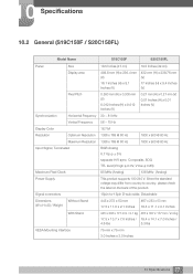
Signal connectors 15pin-to country, please check the label on the back of the product. 10 Specifications 10.2 General (S19C150F / S20C150FL) Model Name S19C150F S20C150FL Panel Size 18.5 Inches (47 cm) 19.5 Inches (49 cm) Display area 409.8 mm (H) x 230.4 mm (V) 16.1 Inches (H) x 9.1 Inches (V) 432 mm (H) x 239.76 mm (V) ...
Signal connectors 15pin-to country, please check the label on the back of the product. 10 Specifications 10.2 General (S19C150F / S20C150FL) Model Name S19C150F S20C150FL Panel Size 18.5 Inches (47 cm) 19.5 Inches (49 cm) Display area 409.8 mm (H) x 230.4 mm (V) 16.1 Inches (H) x 9.1 Inches (V) 432 mm (H) x 239.76 mm (V) ...
User Manual Ver.1.0 (English)
Page 78
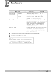
...electronics through an approved recycler. The above specifications are subject to change without notice to our website: www.samsung.com/recyclingdirect or call, (877) 278 - 0799 78 10 Specifications 10 Specifications Model Name Environmental considerations Operating ...Storage Plug-and-Play Panel Dots (Pixels) S19C150F S20C150FL Temperature : 50°F ~ 104°F (10°C ~ 40°C) Humidity : 10 % - 80 %, non-condensing Temperature : -4°F...
...electronics through an approved recycler. The above specifications are subject to change without notice to our website: www.samsung.com/recyclingdirect or call, (877) 278 - 0799 78 10 Specifications 10 Specifications Model Name Environmental considerations Operating ...Storage Plug-and-Play Panel Dots (Pixels) S19C150F S20C150FL Temperature : 50°F ~ 104°F (10°C ~ 40°C) Humidity : 10 % - 80 %, non-condensing Temperature : -4°F...

User Manual Ver.1.0 (English)
Page 79
... the product is not used for an extended period of the product or disconnect the power cable. PowerSaver Power Indicator Power Consumption (S19C150N) Power Consumption (S19C150F) Power Consumption (S20C150FL) Power Consumption (S22C150N) Energy Star Power Consumption On Power saving mode Blinking 13 W Typical 0.3 W 13 W Typical 0.3 W 16 W Typical 0.3 W 23 W Typical 0.3 W Power off...
... the product is not used for an extended period of the product or disconnect the power cable. PowerSaver Power Indicator Power Consumption (S19C150N) Power Consumption (S19C150F) Power Consumption (S20C150FL) Power Consumption (S22C150N) Energy Star Power Consumption On Power saving mode Blinking 13 W Typical 0.3 W 13 W Typical 0.3 W 16 W Typical 0.3 W 23 W Typical 0.3 W Power off...

User Manual Ver.1.0 (English)
Page 80
... the optimum picture quality due to only one resolution for the screen size of the panel. To avoid this, it with the LCD monitor. S19C150N / S19C150F Resolution IBM, 720 x 400 VESA, 640 x 480 MAC, 640 x 480 VESA, 640 x 480 VESA, 640 x 480 VESA, 800 x 600 VESA, 800 x 600 VESA, 800 x 600...
... the optimum picture quality due to only one resolution for the screen size of the panel. To avoid this, it with the LCD monitor. S19C150N / S19C150F Resolution IBM, 720 x 400 VESA, 640 x 480 MAC, 640 x 480 VESA, 640 x 480 VESA, 640 x 480 VESA, 800 x 600 VESA, 800 x 600 VESA, 800 x 600...