
Instruction Manual
Page 1
To ensure proper installation and safety, consult the dealer where the product was purchased. SANYO'S HELP-LINE Call the toll-free number below if you have any difficulties operating this product. 1-800-421-5013 (Weekdays 7:30 AM - 5:00 PM, Pacific Time) INSTRUCTION MANUAL Rear View Back up Camera System CCA-BC200 CAUTION • Installation and wiring require technical expertise and experience.
To ensure proper installation and safety, consult the dealer where the product was purchased. SANYO'S HELP-LINE Call the toll-free number below if you have any difficulties operating this product. 1-800-421-5013 (Weekdays 7:30 AM - 5:00 PM, Pacific Time) INSTRUCTION MANUAL Rear View Back up Camera System CCA-BC200 CAUTION • Installation and wiring require technical expertise and experience.
Instruction Manual
Page 3
... vehicles. A fire or other damage could occur. ʵ2ʵ CONTENTS SAFETY PRECAUTIONS 2 SPECIFICATION 4 BEFORE USING THE REAR VIEW BACK UP CAMERA SYSTEM 5 ACCESSORIES AND HARDWARE 6 REAR VIEW BACK UP CAMERA SYSTEM OUTLINE 7 CAUTIONS FOR CONNECTION 8 CONNECTION 9 BEFORE INSTALLATION 10 INSTALLATION 12 CABLE ROUTING 15 GUIDE LINE ADJUSTMENT AFTER REAR VIEW CAMERA INSTALLATION 17 REAR VIEW CAMERA DISPLAY AND SWITCHING DISPLAY MODES 23 SAFETY PRECAUTIONS • Before using this instruction manual, store it in a place where it can be easily located.
... vehicles. A fire or other damage could occur. ʵ2ʵ CONTENTS SAFETY PRECAUTIONS 2 SPECIFICATION 4 BEFORE USING THE REAR VIEW BACK UP CAMERA SYSTEM 5 ACCESSORIES AND HARDWARE 6 REAR VIEW BACK UP CAMERA SYSTEM OUTLINE 7 CAUTIONS FOR CONNECTION 8 CONNECTION 9 BEFORE INSTALLATION 10 INSTALLATION 12 CABLE ROUTING 15 GUIDE LINE ADJUSTMENT AFTER REAR VIEW CAMERA INSTALLATION 17 REAR VIEW CAMERA DISPLAY AND SWITCHING DISPLAY MODES 23 SAFETY PRECAUTIONS • Before using this instruction manual, store it in a place where it can be easily located.

Instruction Manual
Page 4
.... • Do not use this Rear View Back up Camera System will melt and cause a short, resulting in the steering wheel, shift selector lever, or brake pedal may cause an accident. • Do not splice the cable to connect the power supply to other devices. • After completing the installation and wiring, make sure the brake lights, lights, horn, turn signals, wipers, and other...
.... • Do not use this Rear View Back up Camera System will melt and cause a short, resulting in the steering wheel, shift selector lever, or brake pedal may cause an accident. • Do not splice the cable to connect the power supply to other devices. • After completing the installation and wiring, make sure the brake lights, lights, horn, turn signals, wipers, and other...
Instruction Manual
Page 5
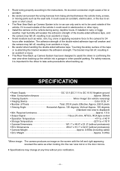
... could result in -car use only and is displayed) • Min. SPECIFICATION • Power Supply DC 12 V (DC 11 V to +176°F • Camera Dimensions W1.1" x H0.9" x D1.0" (without protrusions) • ECU Dimensions W3.4" x H1.1" x D2.6" (without prior notification. ʵ4ʵ An incorrect connection might cause a fire or accident. • Be careful and prevent the wiring harness from being...
... could result in -car use only and is displayed) • Min. SPECIFICATION • Power Supply DC 12 V (DC 11 V to +176°F • Camera Dimensions W1.1" x H0.9" x D1.0" (without protrusions) • ECU Dimensions W3.4" x H1.1" x D2.6" (without prior notification. ʵ4ʵ An incorrect connection might cause a fire or accident. • Be careful and prevent the wiring harness from being...
Instruction Manual
Page 6
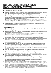
... fluctuations in the light source and vertical lines (streaks) to the vehicle conditions (number of occupants and weight of cargo). BEFORE USING THE REAR VIEW BACK UP CAMERA SYSTEM Regarding methods of use • Do not knock the camera or allow it to the system. • Do not wipe the camera unit and lens area, installation bracket, or camera cable with volatile chemicals...
... fluctuations in the light source and vertical lines (streaks) to the vehicle conditions (number of occupants and weight of cargo). BEFORE USING THE REAR VIEW BACK UP CAMERA SYSTEM Regarding methods of use • Do not knock the camera or allow it to the system. • Do not wipe the camera unit and lens area, installation bracket, or camera cable with volatile chemicals...
Instruction Manual
Page 7
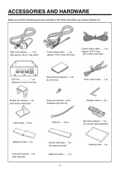
... 1 pc. (Electronic Control Unit box) Hook-and-loop fastener...1 set (for camera)...2 pcs. (Hexagon type, M3 x 6) Hexagon wrench...1 pc. Instruction manual... 1 pc. (with fuse) Control switch cable.......1 pc. (approx. 8.20 ft. long, with warranty) Double sided tape... 1 pc. (for reverse signal detection) Waterproof pad...1 pc. ACCESSORIES AND HARDWARE Make sure all the following parts are included in the Rear View Back up Camera System kit. 1 Rear view camera.........1 pc. (with approx...
... 1 pc. (Electronic Control Unit box) Hook-and-loop fastener...1 set (for camera)...2 pcs. (Hexagon type, M3 x 6) Hexagon wrench...1 pc. Instruction manual... 1 pc. (with fuse) Control switch cable.......1 pc. (approx. 8.20 ft. long, with warranty) Double sided tape... 1 pc. (for reverse signal detection) Waterproof pad...1 pc. ACCESSORIES AND HARDWARE Make sure all the following parts are included in the Rear View Back up Camera System kit. 1 Rear view camera.........1 pc. (with approx...
Instruction Manual
Page 8
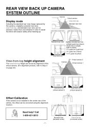
... the camera, a digitally corrected rear view, view-from -top (Virtual camera 2) Offset Calibration If the camera is not installed in order to assist the driver and assure safety when backing up. REAR VIEW BACK UP CAMERA SYSTEM OUTLINE Display mode Including the standard rear view image captured by alignment of the virtual camera. (For alignment process, refer to Step 3 on page 20.) Standard rear view View-from -top (Corrected center) guide line (Light blue...
... the camera, a digitally corrected rear view, view-from -top (Virtual camera 2) Offset Calibration If the camera is not installed in order to assist the driver and assure safety when backing up. REAR VIEW BACK UP CAMERA SYSTEM OUTLINE Display mode Including the standard rear view image captured by alignment of the virtual camera. (For alignment process, refer to Step 3 on page 20.) Standard rear view View-from -top (Corrected center) guide line (Light blue...
Instruction Manual
Page 9
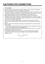
... to the power source of the power supply cable to the accessory (ACC) power supply. * Do not connect this Rear View Back up Camera to the power supply for the camera, which some navigation systems are equipped with. • Connect the brown lead wire to the signal line which switches from 0 V to 12 V when the shift lever is shifted to a pin plug. Otherwise, it while pressing the connector lock. Incomplete connection may cause...
... to the power source of the power supply cable to the accessory (ACC) power supply. * Do not connect this Rear View Back up Camera to the power supply for the camera, which some navigation systems are equipped with. • Connect the brown lead wire to the signal line which switches from 0 V to 12 V when the shift lever is shifted to a pin plug. Otherwise, it while pressing the connector lock. Incomplete connection may cause...
Instruction Manual
Page 10
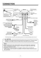
... color and shape of the terminal Connect firmly to a metal part of vehicle (for grounding) Power supply connection terminal (Brown) Power supply cable (Brown) (Black) Connect to the reverse signal cable of vehicle using self-lock conductor included with the unit. • Depending on navigation or external monitor. Refer to "How to point where power is supplied at ignition switch ACC position. (Red) Fuse(1A) Control switch Control switch cable This terminal allows connection of other accessory devices.
... color and shape of the terminal Connect firmly to a metal part of vehicle (for grounding) Power supply connection terminal (Brown) Power supply cable (Brown) (Black) Connect to the reverse signal cable of vehicle using self-lock conductor included with the unit. • Depending on navigation or external monitor. Refer to "How to point where power is supplied at ignition switch ACC position. (Red) Fuse(1A) Control switch Control switch cable This terminal allows connection of other accessory devices.
Instruction Manual
Page 11
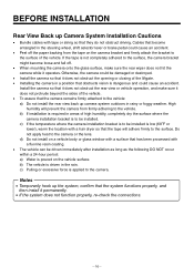
..., re-check the connections. ʵ10ʵ b) The vehicle is dangerous and could cause an accident. • Peel off . • When mounting the camera onto the glass surface, make sure it operates. Notes • Temporarily hook up camera system outdoors in the rain. Install the camera so that it does not obstruct the rear view or vehicle operation, and make sure...
..., re-check the connections. ʵ10ʵ b) The vehicle is dangerous and could cause an accident. • Peel off . • When mounting the camera onto the glass surface, make sure it operates. Notes • Temporarily hook up camera system outdoors in the rain. Install the camera so that it does not obstruct the rear view or vehicle operation, and make sure...
Instruction Manual
Page 12
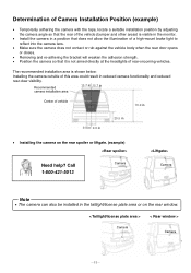
.... (example) Need help? Recommended camera installation area 15.7 in 15.7 in Center of vehicle 70.9 in 9.8 in 9.8 in 29.5 in • Installing the camera on the rear window. < Taillight/license plate area > Camera < Rear window > Camera ʵ11ʵ The recommended installation area is not aimed directly at the headlights of this area could result in reduced camera functionality and reduced rear-view visibility. Determination of Camera Installation Position...
.... (example) Need help? Recommended camera installation area 15.7 in 15.7 in Center of vehicle 70.9 in 9.8 in 9.8 in 29.5 in • Installing the camera on the rear window. < Taillight/license plate area > Camera < Rear window > Camera ʵ11ʵ The recommended installation area is not aimed directly at the headlights of this area could result in reduced camera functionality and reduced rear-view visibility. Determination of Camera Installation Position...
Instruction Manual
Page 13
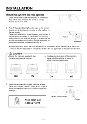
... heat to obtain a correct rear view. Call 1-800-421-5013 Camera mounting screw Camera ʵ12ʵ Bracket • If the temperature where the camera bracket is low, warm the area with the vehicle and ground surface. • Position the lens axis of the bracket to be installed. Install the camera to a flat surface on rear spoiler 1. Bracket Need help? Peel off .
... heat to obtain a correct rear view. Call 1-800-421-5013 Camera mounting screw Camera ʵ12ʵ Bracket • If the temperature where the camera bracket is low, warm the area with the vehicle and ground surface. • Position the lens axis of the bracket to be installed. Install the camera to a flat surface on rear spoiler 1. Bracket Need help? Peel off .
Instruction Manual
Page 14
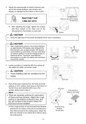
... box adheres to assist the driver. Need help? Approx. 135° Approx. 105° 5. Adjust the camera angle so that the extreme rear end of the vehicle (bumper, rear window, and liftgate.) is a device designed only to floor without using the mating piece. ʵ13ʵ ECU box ECU box Hook-and-loop fastener (Soft side) Hook-and-loop fastener (Rough...
... box adheres to assist the driver. Need help? Approx. 135° Approx. 105° 5. Adjust the camera angle so that the extreme rear end of the vehicle (bumper, rear window, and liftgate.) is a device designed only to floor without using the mating piece. ʵ13ʵ ECU box ECU box Hook-and-loop fastener (Soft side) Hook-and-loop fastener (Rough...
Instruction Manual
Page 15
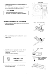
... control switch and attach it stops. Call 1-800-421-5013 4. Control switch How to operate. Fold the self-lock conductor and lock the reverse signal cable. 3. Insert the reverse signal pick-up cable included with the system into the self-lock conductor. Close the self-lock cover and firmly lock it by pinching it is easy to use self-lock conductor 1. CAUTION • Do not install the control switch...
... control switch and attach it stops. Call 1-800-421-5013 4. Control switch How to operate. Fold the self-lock conductor and lock the reverse signal cable. 3. Insert the reverse signal pick-up cable included with the system into the self-lock conductor. Close the self-lock cover and firmly lock it by pinching it is easy to use self-lock conductor 1. CAUTION • Do not install the control switch...
Instruction Manual
Page 16
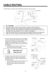
... not block or obstruct vehicle operation. • Route the rear view camera cable as far away from the vehicle antenna as possible from a TV antenna, if equipped. • Clean the areas where the cable clamps and waterproof pad are to be attached. Wipe out oil, wax, moisture, dirt and dust with the cable clamps. Control switch Camera ECU box çCAUTION •...
... not block or obstruct vehicle operation. • Route the rear view camera cable as far away from the vehicle antenna as possible from a TV antenna, if equipped. • Clean the areas where the cable clamps and waterproof pad are to be attached. Wipe out oil, wax, moisture, dirt and dust with the cable clamps. Control switch Camera ECU box çCAUTION •...
Instruction Manual
Page 17
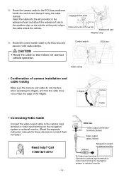
...) Video output cable (Yellow) (Yellow) Navigation system or external monitor To Video input terminal Connect to camera input terminal or video input terminal on the navigation system or external monitor. (Read the separate instruction manuals for these devices to the ECU box positioned inside the vehicle and clamp it does not obstruct vehicle operation. 3. Route the camera cable to connect them correctly.) Need help? Route the control switch cable to 0.1 in the weather strip...
...) Video output cable (Yellow) (Yellow) Navigation system or external monitor To Video input terminal Connect to camera input terminal or video input terminal on the navigation system or external monitor. (Read the separate instruction manuals for these devices to the ECU box positioned inside the vehicle and clamp it does not obstruct vehicle operation. 3. Route the camera cable to connect them correctly.) Need help? Route the control switch cable to 0.1 in the weather strip...
Instruction Manual
Page 18
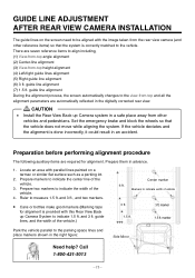
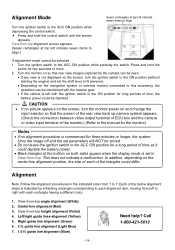
... away from -top height alignment (4) Left/right guide lines alignment (5) Right guide line alignment (6) 3 ft. guide line alignment During the alignment process, the screen automatically changes to the view-from-top and all the alignment parameters are automatically reflected in the digitally corrected rear view. çCAUTION • Install the Rear View Back up Camera System to the parking space lines and place...
... away from -top height alignment (4) Left/right guide lines alignment (5) Right guide line alignment (6) 3 ft. guide line alignment During the alignment process, the screen automatically changes to the view-from-top and all the alignment parameters are automatically reflected in the digitally corrected rear view. çCAUTION • Install the Rear View Back up Camera System to the parking space lines and place...
Instruction Manual
Page 19
... (Blue) Need help? Turn the monitor on so that the screen of the rear view back up camera system appears. (Check the connection between video output terminal of ECU box and the camera or video input terminal of each rectangle having a different color. 1. Left/right guide lines alignment (Yellow) 5. In addition, depending on the screen, turn the monitor power on the navigation system or external monitor connected to this accessory, the operation...
... (Blue) Need help? Turn the monitor on so that the screen of the rear view back up camera system appears. (Check the connection between video output terminal of ECU box and the camera or video input terminal of each rectangle having a different color. 1. Left/right guide lines alignment (Yellow) 5. In addition, depending on the screen, turn the monitor power on the navigation system or external monitor connected to this accessory, the operation...
Instruction Manual
Page 23
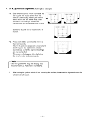
.... The screen will disappear after displaying the view-from the vehicle. guide line to the vehicle. guide line alignment is now set and also 6 ft. guide line may not display as a result of camera installation conditions. 8. After turning the ignition switch off and removing the auxiliary items used for more than two seconds. 7. 1.5 ft. guide line alignment (flashing blue rectangle) 7-1. Set the1.5 ft. Continuously pressing the control switch moves...
.... The screen will disappear after displaying the view-from the vehicle. guide line to the vehicle. guide line alignment is now set and also 6 ft. guide line may not display as a result of camera installation conditions. 8. After turning the ignition switch off and removing the auxiliary items used for more than two seconds. 7. 1.5 ft. guide line alignment (flashing blue rectangle) 7-1. Set the1.5 ft. Continuously pressing the control switch moves...
Instruction Manual
Page 24
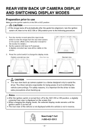
...; Set the selector shift lever to change the display mode. Digitally corrected rear view View-from-top Standard view çç çç çCAUTION • The rear view back up camera system is important for the driver to take extra precautions when backing up. Press the control switch to R (reverse). Notes • After the ignition switch is turned from the rear view camera on the screen. (Refer to the instruction manual for...
...; Set the selector shift lever to change the display mode. Digitally corrected rear view View-from-top Standard view çç çç çCAUTION • The rear view back up camera system is important for the driver to take extra precautions when backing up. Press the control switch to R (reverse). Notes • After the ignition switch is turned from the rear view camera on the screen. (Refer to the instruction manual for...