
Instruction Manual
Page 3
... could occur. • This Rear View Back up Camera System on DC 24V vehicles (such as directed. • Sanyo and its suppliers are not followed properly. • After using the rear view back up camera, read this instruction manual for ...SPECIFICATION 4 BEFORE USING THE REAR VIEW BACK UP CAMERA SYSTEM 5 ACCESSORIES AND HARDWARE 6 REAR VIEW BACK UP CAMERA SYSTEM OUTLINE 7 CAUTIONS FOR CONNECTION 8 CONNECTION 9 BEFORE INSTALLATION 10 INSTALLATION 12 CABLE ROUTING 15 GUIDE LINE ADJUSTMENT AFTER REAR VIEW CAMERA INSTALLATION 17 REAR VIEW CAMERA DISPLAY AND SWITCHING DISPLAY MODES ...
... could occur. • This Rear View Back up Camera System on DC 24V vehicles (such as directed. • Sanyo and its suppliers are not followed properly. • After using the rear view back up camera, read this instruction manual for ...SPECIFICATION 4 BEFORE USING THE REAR VIEW BACK UP CAMERA SYSTEM 5 ACCESSORIES AND HARDWARE 6 REAR VIEW BACK UP CAMERA SYSTEM OUTLINE 7 CAUTIONS FOR CONNECTION 8 CONNECTION 9 BEFORE INSTALLATION 10 INSTALLATION 12 CABLE ROUTING 15 GUIDE LINE ADJUSTMENT AFTER REAR VIEW CAMERA INSTALLATION 17 REAR VIEW CAMERA DISPLAY AND SWITCHING DISPLAY MODES ...

Instruction Manual
Page 4
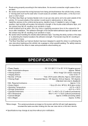
... any metallic areas. Do not modify the cables. • If installing this Rear View Back up Camera System. Otherwise, an accident could result in electrocution. Otherwise, it could occur. • Do not disassemble or modify the Rear View Back up Camera System if it affects operation of the same... To ensure safety, consult the dealer where the Rear View Back up Camera System was purchased. Loose cables which may cause an accident. • Do not splice the cable to connect the power supply to use the Rear View Back up Camera System in the steering wheel, shift selector lever,...
... any metallic areas. Do not modify the cables. • If installing this Rear View Back up Camera System. Otherwise, an accident could result in electrocution. Otherwise, it could occur. • Do not disassemble or modify the Rear View Back up Camera System if it affects operation of the same... To ensure safety, consult the dealer where the Rear View Back up Camera System was purchased. Loose cables which may cause an accident. • Do not splice the cable to connect the power supply to use the Rear View Back up Camera System in the steering wheel, shift selector lever,...
Instruction Manual
Page 5
... may fall off, resulting in confirming the rear view when backing up . The adhesion strength of the vehicle it is displayed) • Min. The bracket may change at any time without protrusions) • Camera Weight Approx. 0.35lbs (including cable) • ECU Weight Approx. 0.37lbs *Mirror image: The camera produces an image on the vehicle during...
... may fall off, resulting in confirming the rear view when backing up . The adhesion strength of the vehicle it is displayed) • Min. The bracket may change at any time without protrusions) • Camera Weight Approx. 0.35lbs (including cable) • ECU Weight Approx. 0.37lbs *Mirror image: The camera produces an image on the vehicle during...
Instruction Manual
Page 6
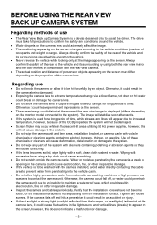
... object. Otherwise it could result in the camera being damaged. • Exposing the camera lens to extreme temperature change via a crack or opening in the camera could cause electrocution, fire, or other irreparable damage. • Inspect the camera and cables periodically. Regarding use • The Rear View Back up Camera System is used for long periods of time...
... object. Otherwise it could result in the camera being damaged. • Exposing the camera lens to extreme temperature change via a crack or opening in the camera could cause electrocution, fire, or other irreparable damage. • Inspect the camera and cables periodically. Regarding use • The Rear View Back up Camera System is used for long periods of time...
Instruction Manual
Page 7
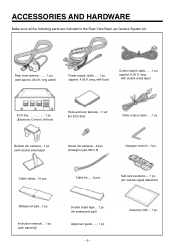
... following parts are included in the Rear View Back up Camera System kit. 1 Rear view camera.........1 pc. (with fuse) Control switch cable.......1 pc. (approx. 8.20 ft. long, with double sided tape) ECU box 1 pc. (Electronic Control Unit box) Hook-and-loop fastener...1 set (for camera)...2 pcs. (Hexagon type, M3 x 6) Hexagon wrench...1 pc. Cable clamp...10 pcs. long, with approx...
... following parts are included in the Rear View Back up Camera System kit. 1 Rear view camera.........1 pc. (with fuse) Control switch cable.......1 pc. (approx. 8.20 ft. long, with double sided tape) ECU box 1 pc. (Electronic Control Unit box) Hook-and-loop fastener...1 set (for camera)...2 pcs. (Hexagon type, M3 x 6) Hexagon wrench...1 pc. Cable clamp...10 pcs. long, with approx...
Instruction Manual
Page 9
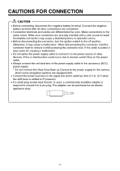
...disconnecting the connector, hold the connector itself to the power source of the power supply cable to the accessory (ACC) power supply. * Do not connect this Rear View Back up Camera to the power supply for the camera, which some navigation systems are equipped with. • Connect the brown lead wire... to the signal line which switches from 0 V to 12 V when the shift lever is shifted to a pin plug. If the cable is pulled, it ...
...disconnecting the connector, hold the connector itself to the power source of the power supply cable to the accessory (ACC) power supply. * Do not connect this Rear View Back up Camera to the power supply for the camera, which some navigation systems are equipped with. • Connect the brown lead wire... to the signal line which switches from 0 V to 12 V when the shift lever is shifted to a pin plug. If the cable is pulled, it ...
Instruction Manual
Page 10
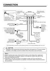
... also refer to the manual provided with the Rear View Back up camera system may not function as expected. CONNECTION Control switch connection terminal (Green) ECU box Rear view camera connection terminal (Black) Connect the cable according to the color and shape of the terminal...Black) Video output connection terminal (Yellow) (Yellow) Video output cable (RCA Type) (Yellow) Rear view camera Connect to Camera input terminal or video input terminal on the type of vehicle or navigation system, the rear view back up Camera System. Connect to use . çCAUTION • Installation ...
... also refer to the manual provided with the Rear View Back up camera system may not function as expected. CONNECTION Control switch connection terminal (Green) ECU box Rear view camera connection terminal (Black) Connect the cable according to the color and shape of the terminal...Black) Video output connection terminal (Yellow) (Yellow) Video output cable (RCA Type) (Yellow) Rear view camera Connect to Camera input terminal or video input terminal on the type of vehicle or navigation system, the rear view back up Camera System. Connect to use . çCAUTION • Installation ...
Instruction Manual
Page 11
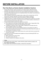
... or excessive force is not completely adhered to the vehicle. BEFORE INSTALLATION Rear View Back up Camera System Installation Cautions • Bundle cables with tape or string so that the tape will prevent the camera from the tape on the camera bracket and firmly attach the bracket to the surface of the vehicle. c) If the temperature...
... or excessive force is not completely adhered to the vehicle. BEFORE INSTALLATION Rear View Back up Camera System Installation Cautions • Bundle cables with tape or string so that the tape will prevent the camera from the tape on the camera bracket and firmly attach the bracket to the surface of the vehicle. c) If the temperature...
Instruction Manual
Page 14
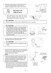
...to assist the driver. Note • There are within connection reach. çCAUTION • Avoid installing near the ventilators for the heater. 6. The rear view back up and down. Peel off the paper backing from the Hook-and-loop fastener (1 set.), adhere each piece of the ECU box, and install... the left and right, and an approximate 105-degree view between up camera system is displayed at the lower end of the Loosen oblong holes in Step 5. Locate a position to install the ECU box where all the cables are separate surfaces for the mating piece, attach the ECU box directly to...
...to assist the driver. Note • There are within connection reach. çCAUTION • Avoid installing near the ventilators for the heater. 6. The rear view back up and down. Peel off the paper backing from the Hook-and-loop fastener (1 set.), adhere each piece of the ECU box, and install... the left and right, and an approximate 105-degree view between up camera system is displayed at the lower end of the Loosen oblong holes in Step 5. Locate a position to install the ECU box where all the cables are separate surfaces for the mating piece, attach the ECU box directly to...
Instruction Manual
Page 15
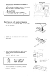
... operate. 7. CAUTION • Do not install the control switch in a position where it with pliers. ʵ14ʵ Cable stopper Reverse signal pick-up cable (Brown) included with system (Brown) Call 1-800-421-5013 4. Fold the self-lock conductor and lock the reverse signal... cable. 3. Install the control switch in a position that obstructs vehicle operation. Need help? Insert the reverse signal pick-up cable included with the system into the self-lock conductor. Peel off the paper ...
... operate. 7. CAUTION • Do not install the control switch in a position where it with pliers. ʵ14ʵ Cable stopper Reverse signal pick-up cable (Brown) included with system (Brown) Call 1-800-421-5013 4. Fold the self-lock conductor and lock the reverse signal... cable. 3. Install the control switch in a position that obstructs vehicle operation. Need help? Insert the reverse signal pick-up cable included with the system into the self-lock conductor. Peel off the paper ...
Instruction Manual
Page 16
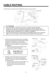
...hinge and harness cover. • Route the cable carefully so that it with AM radio band reception. Straighten the cable along the top of the liftgate and secure it does not block or obstruct vehicle operation. • Route the rear view camera cable as far away from the vehicle antenna as ...possible from a TV antenna, if equipped. • Clean the areas where the cable clamps and waterproof pad are to enable smooth opening at the side of the...
...hinge and harness cover. • Route the cable carefully so that it with AM radio band reception. Straighten the cable along the top of the liftgate and secure it does not block or obstruct vehicle operation. • Route the rear view camera cable as far away from the vehicle antenna as ...possible from a TV antenna, if equipped. • Clean the areas where the cable clamps and waterproof pad are to enable smooth opening at the side of the...
Instruction Manual
Page 17
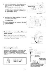
... 0.1 in waterproof pad and attach the waterproof pad to camera input terminal or video input terminal on the rear side Waterproof pad Weather strip 4. Route the camera cable to connect them correctly.) Need help? Liftgate Camera Cable • Connecting Video Cable Connect the video output cable to the camera input terminal or video input terminal on the navigation system...
... 0.1 in waterproof pad and attach the waterproof pad to camera input terminal or video input terminal on the rear side Waterproof pad Weather strip 4. Route the camera cable to connect them correctly.) Need help? Liftgate Camera Cable • Connecting Video Cable Connect the video output cable to the camera input terminal or video input terminal on the navigation system...