
Instruction Manual
Page 1
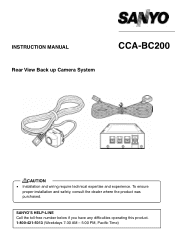
SANYO'S HELP-LINE Call the toll-free number below if you have any difficulties operating this product. 1-800-421-5013 (Weekdays 7:30 AM - 5:00 PM, Pacific Time) INSTRUCTION MANUAL Rear View Back up Camera System CCA-BC200 CAUTION • Installation and wiring require technical expertise and experience. To ensure proper installation and safety, consult the dealer where the product was purchased.
SANYO'S HELP-LINE Call the toll-free number below if you have any difficulties operating this product. 1-800-421-5013 (Weekdays 7:30 AM - 5:00 PM, Pacific Time) INSTRUCTION MANUAL Rear View Back up Camera System CCA-BC200 CAUTION • Installation and wiring require technical expertise and experience. To ensure proper installation and safety, consult the dealer where the product was purchased.
Instruction Manual
Page 3
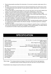
..., shift selector lever, or brake pedal when driving, or jeopardizes the safety of the product as directed. • Sanyo and its suppliers are not followed properly. • After using the rear view back up Camera System on DC 24V vehicles (such as trucks, buses). Do not use with DC 12V, negative ground vehicles. Electrocution...
..., shift selector lever, or brake pedal when driving, or jeopardizes the safety of the product as directed. • Sanyo and its suppliers are not followed properly. • After using the rear view back up Camera System on DC 24V vehicles (such as trucks, buses). Do not use with DC 12V, negative ground vehicles. Electrocution...

Instruction Manual
Page 4
.../experience. If a non-specified part is used , a fire or malfunction could occur. • Do not disassemble or modify the Rear View Back up Camera System if it appears damaged such as when there is no display or sound output. Disassembly prohibited. It could result in an accident,... Do not use nuts and bolts from contact, causing a fire or electrocution. ʵ3ʵ • When installing this Rear View Back up Camera System to use the Rear View Back up Camera System in the steering wheel, shift selector lever, or brake pedal may cause fire or smoke. • Do not install...
.../experience. If a non-specified part is used , a fire or malfunction could occur. • Do not disassemble or modify the Rear View Back up Camera System if it appears damaged such as when there is no display or sound output. Disassembly prohibited. It could result in an accident,... Do not use nuts and bolts from contact, causing a fire or electrocution. ʵ3ʵ • When installing this Rear View Back up Camera System to use the Rear View Back up Camera System in the steering wheel, shift selector lever, or brake pedal may cause fire or smoke. • Do not install...
Instruction Manual
Page 5
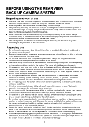
...has been designed to assist the driver in -car use only and is not to an open or short circuit. • The Rear View Back up Camera System is used outside of the vehicle it could cause an accident, electrocution, or fire due to be used outside of the double... adhesion strength. Consumption Ampere Approx. 300mA • Viewing System Mirror Image* (for 24 hours after installation. If installed in rainy or foggy weather, high humidity will weaken and the camera may fall off , resulting in an accident or injury. • This Rear View Back up . • Route wiring properly according ...
...has been designed to assist the driver in -car use only and is not to an open or short circuit. • The Rear View Back up Camera System is used outside of the vehicle it could cause an accident, electrocution, or fire due to be used outside of the double... adhesion strength. Consumption Ampere Approx. 300mA • Viewing System Mirror Image* (for 24 hours after installation. If installed in rainy or foggy weather, high humidity will weaken and the camera may fall off , resulting in an accident or injury. • This Rear View Back up . • Route wiring properly according ...
Instruction Manual
Page 6
... an accident or injury. • If direct sunlight or strong light (sunlight reflected from the installation surface. Regarding use • The Rear View Back up Camera System is not separating from the bumper, or headlights) is used for long periods of time. The image will not cause damage to ...the system. • Do not wipe the camera unit and lens area, installation bracket, or camera cable with the rear view camera. • The actual position and distance of persons or objects appearing on the screen may occur while in ...
... an accident or injury. • If direct sunlight or strong light (sunlight reflected from the installation surface. Regarding use • The Rear View Back up Camera System is not separating from the bumper, or headlights) is used for long periods of time. The image will not cause damage to ...the system. • Do not wipe the camera unit and lens area, installation bracket, or camera cable with the rear view camera. • The actual position and distance of persons or objects appearing on the screen may occur while in ...
Instruction Manual
Page 7
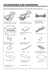
... reverse signal detection) Waterproof pad...1 pc. Cable tie......2 pcs. ACCESSORIES AND HARDWARE Make sure all the following parts are included in the Rear View Back up Camera System kit. 1 Rear view camera.........1 pc. (with double sided tape) Screw (for camera)...2 pcs. (Hexagon type, M3 x 6) Hexagon wrench...1 pc. long, with fuse) Control switch cable.......1 pc. (approx. 8.20 ft...
... reverse signal detection) Waterproof pad...1 pc. Cable tie......2 pcs. ACCESSORIES AND HARDWARE Make sure all the following parts are included in the Rear View Back up Camera System kit. 1 Rear view camera.........1 pc. (with double sided tape) Screw (for camera)...2 pcs. (Hexagon type, M3 x 6) Hexagon wrench...1 pc. long, with fuse) Control switch cable.......1 pc. (approx. 8.20 ft...
Instruction Manual
Page 8
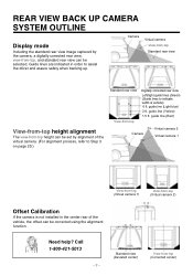
...Camera Virtual camera View-from-top Standard rear view View-from-top height alignment The view-from-top height can be set by the camera, a digitally corrected rear view, view-from -top (Corrected center) Need help? Call 1-800-421-5013 ʵ7ʵ Standard view (Deviated center) View-from -top, and standard rear view... 1.5 ft. Guide lines are indicated in the center rear of vehicle) 6 ft. guide line (Red) Camera Virtual camera 2 Virtual camera 1 View-from-top (Virtual camera 1) View-from -top Digitally corrected rear view Left/right guide lines (Green) (Guide lines to assist...
...Camera Virtual camera View-from-top Standard rear view View-from-top height alignment The view-from-top height can be set by the camera, a digitally corrected rear view, view-from -top (Corrected center) Need help? Call 1-800-421-5013 ʵ7ʵ Standard view (Deviated center) View-from -top, and standard rear view... 1.5 ft. Guide lines are indicated in the center rear of vehicle) 6 ft. guide line (Red) Camera Virtual camera 2 Virtual camera 1 View-from-top (Virtual camera 1) View-from -top Digitally corrected rear view Left/right guide lines (Green) (Guide lines to assist...
Instruction Manual
Page 9
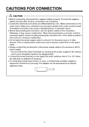
... connect it to the power source of the power supply cable to the accessory (ACC) power supply. * Do not connect this Rear View Back up Camera to the power supply for the camera, which some navigation systems are equipped with. • Connect the brown lead wire to the signal line which switches from 0 V to...
... connect it to the power source of the power supply cable to the accessory (ACC) power supply. * Do not connect this Rear View Back up Camera to the power supply for the camera, which some navigation systems are equipped with. • Connect the brown lead wire to the signal line which switches from 0 V to...
Instruction Manual
Page 10
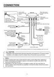
... connection terminal (Yellow) (Yellow) Video output cable (RCA Type) (Yellow) Rear view camera Connect to Camera input terminal or video input terminal on the type of vehicle or navigation system, the rear view back up Camera System. Refer to "How to use . çCAUTION • Installation and...or an external monitor, also refer to the manual provided with the Rear View Back up camera system may not function as expected. CONNECTION Control switch connection terminal (Green) ECU box Rear view camera connection terminal (Black) Connect the cable according to the color and shape...
... connection terminal (Yellow) (Yellow) Video output cable (RCA Type) (Yellow) Rear view camera Connect to Camera input terminal or video input terminal on the type of vehicle or navigation system, the rear view back up Camera System. Refer to "How to use . çCAUTION • Installation and...or an external monitor, also refer to the manual provided with the Rear View Back up camera system may not function as expected. CONNECTION Control switch connection terminal (Green) ECU box Rear view camera connection terminal (Black) Connect the cable according to the color and shape...
Instruction Manual
Page 11
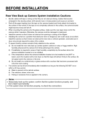
...with a surface that has been processed with tape or string so that the camera remains firmly attached to the vehicle: a) Do not install the rear view back up camera system outdoors in the rain. Otherwise, the camera could cause an accident. High humidity will adhere firmly to the surface. ...sides of the vehicle. • To assure that they do not obstruct driving. Do not apply heat to the camera or the lens. BEFORE INSTALLATION Rear View Back up Camera System Installation Cautions • Bundle cables with a fluorine resin coating. • The vehicle can be driven immediately ...
...with a surface that has been processed with tape or string so that the camera remains firmly attached to the vehicle: a) Do not install the rear view back up camera system outdoors in the rain. Otherwise, the camera could cause an accident. High humidity will adhere firmly to the surface. ...sides of the vehicle. • To assure that they do not obstruct driving. Do not apply heat to the camera or the lens. BEFORE INSTALLATION Rear View Back up Camera System Installation Cautions • Bundle cables with a fluorine resin coating. • The vehicle can be driven immediately ...
Instruction Manual
Page 12
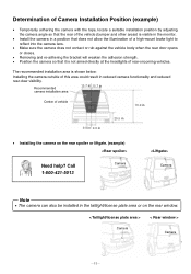
... recommended installation area is shown below: Installing the camera outside of vehicle 70.9 in 9.8 in 9.8 in 29.5 in reduced camera functionality and reduced rear-view visibility. Recommended camera installation area 15.7 in 15.7 in Center of this area could result in • Installing the camera on the rear window. < Taillight/license plate area > Camera < Rear window > Camera ʵ11ʵ
... recommended installation area is shown below: Installing the camera outside of vehicle 70.9 in 9.8 in 9.8 in 29.5 in reduced camera functionality and reduced rear-view visibility. Recommended camera installation area 15.7 in 15.7 in Center of this area could result in • Installing the camera on the rear window. < Taillight/license plate area > Camera < Rear window > Camera ʵ11ʵ
Instruction Manual
Page 13
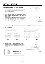
...Install the camera (SANYO logo facing upward) using the screws. Bracket Need help? Press the bracket with the vehicle and ground surface. • Position the lens axis of the camera square to the vehicle in a loose installation that the tape adheres firmly to obtain a correct rear view. Touching... the sticky surface of the vehicle. Call 1-800-421-5013 Camera mounting screw Camera ʵ12ʵ Do not apply heat to the camera or the lens. çCAUTION • Mount the camera level with a finger to assure good ...
...Install the camera (SANYO logo facing upward) using the screws. Bracket Need help? Press the bracket with the vehicle and ground surface. • Position the lens axis of the camera square to the vehicle in a loose installation that the tape adheres firmly to obtain a correct rear view. Touching... the sticky surface of the vehicle. Call 1-800-421-5013 Camera mounting screw Camera ʵ12ʵ Do not apply heat to the camera or the lens. çCAUTION • Mount the camera level with a finger to assure good ...
Instruction Manual
Page 14
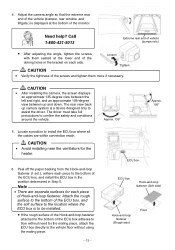
Adjust the camera angle so that the extreme rear end of the vehicle (bumper, rear window, and liftgate.) is displayed at the lower end of the Loosen oblong holes in Step 5. Call 1-800-421-5013 Extreme rear end of the ECU box, and the soft surface to the location where the ECU ... them more if necessary. çCAUTION • After installing the camera, the screen displays an approximate 135-degree view between the left and right, and an approximate 105-degree view between up and down. Need help? The rear view back up camera system is to be installed. • If the rough surface of...
Adjust the camera angle so that the extreme rear end of the vehicle (bumper, rear window, and liftgate.) is displayed at the lower end of the Loosen oblong holes in Step 5. Call 1-800-421-5013 Extreme rear end of the ECU box, and the soft surface to the location where the ECU ... them more if necessary. çCAUTION • After installing the camera, the screen displays an approximate 135-degree view between the left and right, and an approximate 105-degree view between up and down. Need help? The rear view back up camera system is to be installed. • If the rough surface of...
Instruction Manual
Page 16
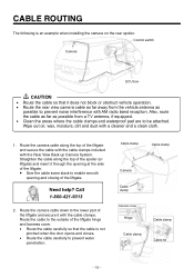
...; Clean the areas where the cable clamps and waterproof pad are to be attached. Wipe out oil, wax, moisture, dirt and dust with the Rear View Back up Camera System. Call 1-800-421-5013 2. Need help? CABLE ROUTING The following is not pinched when the door opens and closes. • Route the cable... down to the lower part of the liftgate and secure it does not block or obstruct vehicle operation. • Route the rear view camera cable as possible to the outside of the liftgate and secure the cable with the cable clamps included with a cleaner and a clean cloth. 1. Route the ...
...; Clean the areas where the cable clamps and waterproof pad are to be attached. Wipe out oil, wax, moisture, dirt and dust with the Rear View Back up Camera System. Call 1-800-421-5013 2. Need help? CABLE ROUTING The following is not pinched when the door opens and closes. • Route the cable... down to the lower part of the liftgate and secure it does not block or obstruct vehicle operation. • Route the rear view camera cable as possible to the outside of the liftgate and secure the cable with the cable clamps included with a cleaner and a clean cloth. 1. Route the ...
Instruction Manual
Page 18
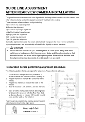
.... 1.5 ft. 3 ft. There are automatically reflected in the digitally corrected rear view. çCAUTION • Install the Rear View Back up Camera System to align including, (1) View-from-top angle alignment (2) Center-line alignment (3) View-from -top and all the alignment parameters are seven reference items to indicate ... marker Park the vehicle parallel to indicate the center line of the vehicle.) Center marker 6 ft. GUIDE LINE ADJUSTMENT AFTER REAR VIEW CAMERA INSTALLATION The guide lines on a tarmac or similar flat surface such as a parking lot. 2. Locate an area with parallel...
.... 1.5 ft. 3 ft. There are automatically reflected in the digitally corrected rear view. çCAUTION • Install the Rear View Back up Camera System to align including, (1) View-from-top angle alignment (2) Center-line alignment (3) View-from -top and all the alignment parameters are seven reference items to indicate ... marker Park the vehicle parallel to indicate the center line of the vehicle.) Center marker 6 ft. GUIDE LINE ADJUSTMENT AFTER REAR VIEW CAMERA INSTALLATION The guide lines on a tarmac or similar flat surface such as a parking lot. 2. Locate an area with parallel...
Instruction Manual
Page 19
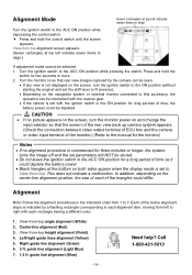
... will NOT be selected 1. View-from -top height alignment (Violet) 4. guide line alignment (Light Blue) 7. 1.5 ft. Turn the ignition switch to the ACC ON position while pressing the switch. Turn the monitor on so that the screen of the rear view back up camera system appears. (Check the ...connection between video output terminal of ECU box and the camera or video input terminal of the below alignment steps is commenced for two seconds or more...
... will NOT be selected 1. View-from -top height alignment (Violet) 4. guide line alignment (Light Blue) 7. 1.5 ft. Turn the ignition switch to the ACC ON position while pressing the switch. Turn the monitor on so that the screen of the rear view back up camera system appears. (Check the ...connection between video output terminal of ECU box and the camera or video input terminal of the below alignment steps is commenced for two seconds or more...
Instruction Manual
Page 24
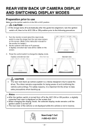
... control switch to R (reverse). The driver remains responsible for the driver to take extra precautions when backing up. Digitally corrected rear view View-from the rear view camera on the screen. (Refer to the instruction manual for the monitor for details.) 2. Notes • After the ignition switch ...display mode, the selected display mode remains until the ignition switch is turned off. • The rear view of and confirming the vehicle surroundings. REAR VIEW BACK UP CAMERA DISPLAY AND SWITCHING DISPLAY MODES Preparation prior to use Make sure the ignition switch is in reverse. ...
... control switch to R (reverse). The driver remains responsible for the driver to take extra precautions when backing up. Digitally corrected rear view View-from the rear view camera on the screen. (Refer to the instruction manual for the monitor for details.) 2. Notes • After the ignition switch ...display mode, the selected display mode remains until the ignition switch is turned off. • The rear view of and confirming the vehicle surroundings. REAR VIEW BACK UP CAMERA DISPLAY AND SWITCHING DISPLAY MODES Preparation prior to use Make sure the ignition switch is in reverse. ...