
Instruction Manual
Page 1
SANYO'S HELP-LINE Call the toll-free number below if you have any difficulties operating this product. 1-800-421-5013 (Weekdays 7:30 AM - 5:00 PM, Pacific Time) INSTRUCTION MANUAL Rear View Back up Camera System CCA-BC200 CAUTION • Installation and wiring require technical expertise and experience. To ensure proper installation and safety, consult the dealer where the product was purchased.
SANYO'S HELP-LINE Call the toll-free number below if you have any difficulties operating this product. 1-800-421-5013 (Weekdays 7:30 AM - 5:00 PM, Pacific Time) INSTRUCTION MANUAL Rear View Back up Camera System CCA-BC200 CAUTION • Installation and wiring require technical expertise and experience. To ensure proper installation and safety, consult the dealer where the product was purchased.
Instruction Manual
Page 3
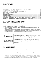
...manual. Do not use this Rear View Back up Camera System on DC 24V vehicles (such as directed. • Sanyo and its suppliers are not followed properly. • After using the rear view back up Camera System is ignored. WARNING &#...SPECIFICATION 4 BEFORE USING THE REAR VIEW BACK UP CAMERA SYSTEM 5 ACCESSORIES AND HARDWARE 6 REAR VIEW BACK UP CAMERA SYSTEM OUTLINE 7 CAUTIONS FOR CONNECTION 8 CONNECTION 9 BEFORE INSTALLATION 10 INSTALLATION 12 CABLE ROUTING 15 GUIDE LINE ADJUSTMENT AFTER REAR VIEW CAMERA INSTALLATION 17 REAR VIEW CAMERA DISPLAY AND SWITCHING DISPLAY MODES ...
...manual. Do not use this Rear View Back up Camera System on DC 24V vehicles (such as directed. • Sanyo and its suppliers are not followed properly. • After using the rear view back up Camera System is ignored. WARNING &#...SPECIFICATION 4 BEFORE USING THE REAR VIEW BACK UP CAMERA SYSTEM 5 ACCESSORIES AND HARDWARE 6 REAR VIEW BACK UP CAMERA SYSTEM OUTLINE 7 CAUTIONS FOR CONNECTION 8 CONNECTION 9 BEFORE INSTALLATION 10 INSTALLATION 12 CABLE ROUTING 15 GUIDE LINE ADJUSTMENT AFTER REAR VIEW CAMERA INSTALLATION 17 REAR VIEW CAMERA DISPLAY AND SWITCHING DISPLAY MODES ...

Instruction Manual
Page 4
...the dealer where the product was purchased. Otherwise, an accident could result in mind.) • Do not use the Rear View Back up Camera System was purchased to determine the installation position, keeping safety in an accident, fire, or electrocution. • If power to the power cable has been... or dust can be damaged from the ECU box cannot be used, it does not come into the vehicle body to install this Rear View Back up Camera System, check the locations of improper attachment, resulting in the specified manner. Loose cables which may become entangled in electrocution....
...the dealer where the product was purchased. Otherwise, an accident could result in mind.) • Do not use the Rear View Back up Camera System was purchased to determine the installation position, keeping safety in an accident, fire, or electrocution. • If power to the power cable has been... or dust can be damaged from the ECU box cannot be used, it does not come into the vehicle body to install this Rear View Back up Camera System, check the locations of improper attachment, resulting in the specified manner. Loose cables which may become entangled in electrocution....
Instruction Manual
Page 5
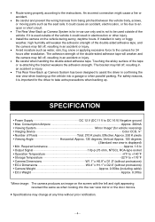
... surface of the vehicle it could cause an accident, electrocution, or fire due to an open or short circuit. • The Rear View Back up Camera System is for 24 hours after installation. The adhesion strength of the double-sided adhesive tape will weaken the adhesion strength of the double-sided adhesive tape, and...
... surface of the vehicle it could cause an accident, electrocution, or fire due to an open or short circuit. • The Rear View Back up Camera System is for 24 hours after installation. The adhesion strength of the double-sided adhesive tape will weaken the adhesion strength of the double-sided adhesive tape, and...
Instruction Manual
Page 6
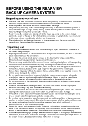
... installation bracket, or camera cable with excessive force using a dry cloth could adversely affect the image. • The positioning appearing on the screen changes according to increased temperature, however, because of the CCD properties the system will not be hit forcefully by using both the rear view ...mirror and the door mirrors in combination with the rear view camera. • The actual position and distance of persons or objects appearing on the screen may occur while...
... installation bracket, or camera cable with excessive force using a dry cloth could adversely affect the image. • The positioning appearing on the screen changes according to increased temperature, however, because of the CCD properties the system will not be hit forcefully by using both the rear view ...mirror and the door mirrors in combination with the rear view camera. • The actual position and distance of persons or objects appearing on the screen may occur while...
Instruction Manual
Page 8
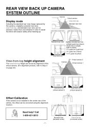
... to Step 3 on page 20.) Standard rear view View-from -top (Virtual camera 2) Offset Calibration If the camera is not installed in order to indicate width of the vehicle, the offset can be corrected using the alignment function. guide line (Red) Camera Virtual camera 2 Virtual camera 1 View-from-top (Virtual camera 1) View-from -top Digitally corrected rear view Left/right guide lines (Green) (Guide...
... to Step 3 on page 20.) Standard rear view View-from -top (Virtual camera 2) Offset Calibration If the camera is not installed in order to indicate width of the vehicle, the offset can be corrected using the alignment function. guide line (Red) Camera Virtual camera 2 Virtual camera 1 View-from-top (Virtual camera 1) View-from -top Digitally corrected rear view Left/right guide lines (Green) (Guide...
Instruction Manual
Page 10
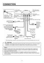
... the manual provided with the Rear View Back up camera system may not function as expected. Connect to use . çCAUTION • Installation and wiring require technical expertise and experience. To ensure proper installation and safety, consult the dealer... where the product was purchased. ʵ9ʵ Do not remove cap/sleeve when not in use self-lock conductor". (Brown) Self-lock conductor (Green) (Black) Video output connection terminal (Yellow) (Yellow) Video output cable (RCA Type) (Yellow) Rear view camera Connect to Camera...
... the manual provided with the Rear View Back up camera system may not function as expected. Connect to use . çCAUTION • Installation and wiring require technical expertise and experience. To ensure proper installation and safety, consult the dealer... where the product was purchased. ʵ9ʵ Do not remove cap/sleeve when not in use self-lock conductor". (Brown) Self-lock conductor (Green) (Black) Video output connection terminal (Yellow) (Yellow) Video output cable (RCA Type) (Yellow) Rear view camera Connect to Camera...
Instruction Manual
Page 11
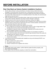
... in the steering wheel, shift selector lever or brake pedal could cause an accident. BEFORE INSTALLATION Rear View Back up Camera System Installation Cautions • Bundle cables with a fluorine resin coating. • The vehicle can be damaged or destroyed. • Install the camera so that it does not obstruct the opening or closing of the vehicle. •...
... in the steering wheel, shift selector lever or brake pedal could cause an accident. BEFORE INSTALLATION Rear View Back up Camera System Installation Cautions • Bundle cables with a fluorine resin coating. • The vehicle can be damaged or destroyed. • Install the camera so that it does not obstruct the opening or closing of the vehicle. •...
Instruction Manual
Page 12
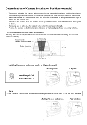
... the camera does not contact or rub against the vehicle body when the rear door opens or closes. • Removing and re-adhering the bracket will weaken the adhesion strength. • Position the camera so that it is shown below: Installing the camera outside of this area could result in reduced camera functionality and reduced rear-view visibility...
... the camera does not contact or rub against the vehicle body when the rear door opens or closes. • Removing and re-adhering the bracket will weaken the adhesion strength. • Position the camera so that it is shown below: Installing the camera outside of this area could result in reduced camera functionality and reduced rear-view visibility...
Instruction Manual
Page 13
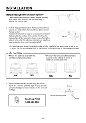
... a hair dryer so that could eventually fall off. Install the camera to obtain a correct rear view. Wipe off the paper backing from the tape on the camera bracket and firmly attach the bracket to the surface. Press...Camera mounting screw Camera ʵ12ʵ Install the camera (SANYO logo facing upward) using the hexagon wrench included in a loose installation that the tape adheres firmly to a flat surface on rear spoiler 1. Bracket • If the temperature where the camera bracket is to be installed. OK NG OK NG 3. INSTALLATION Installing system on the rear...
... a hair dryer so that could eventually fall off. Install the camera to obtain a correct rear view. Wipe off the paper backing from the tape on the camera bracket and firmly attach the bracket to the surface. Press...Camera mounting screw Camera ʵ12ʵ Install the camera (SANYO logo facing upward) using the hexagon wrench included in a loose installation that the tape adheres firmly to a flat surface on rear spoiler 1. Bracket • If the temperature where the camera bracket is to be installed. OK NG OK NG 3. INSTALLATION Installing system on the rear...
Instruction Manual
Page 14
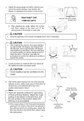
.... çCAUTION • After installing the camera, the screen displays an approximate 135-degree view between the left and right, and an approximate 105-degree view between up camera system is displayed at the lower end of the Loosen oblong holes in Step 5. Locate a position to assist the driver. 4. The rear view back up and down. Peel...
.... çCAUTION • After installing the camera, the screen displays an approximate 135-degree view between the left and right, and an approximate 105-degree view between up camera system is displayed at the lower end of the Loosen oblong holes in Step 5. Locate a position to assist the driver. 4. The rear view back up and down. Peel...
Instruction Manual
Page 15
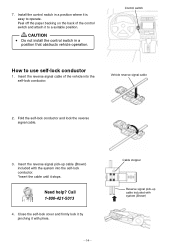
Vehicle reverse signal cable 2. Need help? Install the control switch in a position that obstructs vehicle operation. Fold the self-lock conductor and lock the reverse signal cable. 3. Close the self-lock cover ... included with the system into the self-lock conductor. Call 1-800-421-5013 4. Control switch How to use self-lock conductor 1. CAUTION • Do not install the control switch in a position where it is easy to a suitable position. Insert the reverse signal cable of the control switch and attach it stops. 7.
Vehicle reverse signal cable 2. Need help? Install the control switch in a position that obstructs vehicle operation. Fold the self-lock conductor and lock the reverse signal cable. 3. Close the self-lock cover ... included with the system into the self-lock conductor. Call 1-800-421-5013 4. Control switch How to use self-lock conductor 1. CAUTION • Do not install the control switch in a position where it is easy to a suitable position. Insert the reverse signal cable of the control switch and attach it stops. 7.
Instruction Manual
Page 16
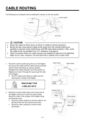
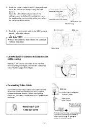
... to prevent water penetration. Control switch Camera ECU box çCAUTION • Route the cable so that the cable is an example when installing the camera on the rear spoiler. Wipe out oil, wax, moisture, dirt and dust with the Rear View Back up Camera System. Need help? Straighten the cable... along the top of the liftgate. Route the camera cable down to the lower part of ...
... to prevent water penetration. Control switch Camera ECU box çCAUTION • Route the cable so that the cable is an example when installing the camera on the rear spoiler. Wipe out oil, wax, moisture, dirt and dust with the Rear View Back up Camera System. Need help? Straighten the cable... along the top of the liftgate. Route the camera cable down to the lower part of ...
Instruction Manual
Page 17
...8226; Route the cable so that the cable does not contact the edge of the liftgate. Liftgate Camera Cable • Connecting Video Cable Connect the video output cable to the camera input terminal or video input terminal on the vehicle at the point where the cable enters the vehicle... it does not obstruct vehicle operation. Position with cable clamps. Control switch ECU box Cable clamp • Confirmation of camera installation and cable routing Make sure the camera and cable do not interfere when operating the liftgate, and that it using the cable clamps. Route the...
...8226; Route the cable so that the cable does not contact the edge of the liftgate. Liftgate Camera Cable • Connecting Video Cable Connect the video output cable to the camera input terminal or video input terminal on the vehicle at the point where the cable enters the vehicle... it does not obstruct vehicle operation. Position with cable clamps. Control switch ECU box Cable clamp • Confirmation of camera installation and cable routing Make sure the camera and cable do not interfere when operating the liftgate, and that it using the cable clamps. Route the...
Instruction Manual
Page 18
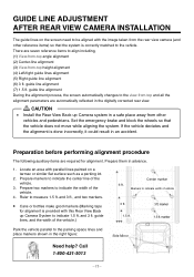
... guide lines alignment (5) Right guide line alignment (6) 3 ft. Prepare two markers to indicate the width of the vehicle.) Center marker 6 ft. GUIDE LINE ADJUSTMENT AFTER REAR VIEW CAMERA INSTALLATION The guide lines on a tarmac or similar flat surface such as a parking lot. 2. guide lines, and the width of the vehicle. 4. Locate an area with...
... guide lines alignment (5) Right guide line alignment (6) 3 ft. Prepare two markers to indicate the width of the vehicle.) Center marker 6 ft. GUIDE LINE ADJUSTMENT AFTER REAR VIEW CAMERA INSTALLATION The guide lines on a tarmac or similar flat surface such as a parking lot. 2. guide lines, and the width of the vehicle. 4. Locate an area with...
Instruction Manual
Page 23
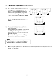
.... marker. 7-2. Press and hold the control switch for alignment, move the vehicle to a safe place. ʵ22ʵ The screen will disappear after displaying the view-from the vehicle. Note • The 6 ft. guide line alignment (flashing blue rectangle) 7-1. guide line may not display as a result of camera installation conditions. 8.
.... marker. 7-2. Press and hold the control switch for alignment, move the vehicle to a safe place. ʵ22ʵ The screen will disappear after displaying the view-from the vehicle. Note • The 6 ft. guide line alignment (flashing blue rectangle) 7-1. guide line may not display as a result of camera installation conditions. 8.