
Instruction Manual
Page 7
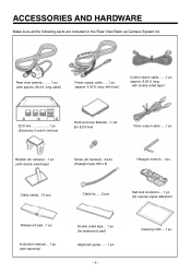
.... (approx. 4.92 ft. Instruction manual... 1 pc. (with fuse) Control switch cable.......1 pc. (approx. 8.20 ft. long, with warranty) Double sided tape... 1 pc. (for reverse signal detection) Waterproof pad...1 pc. ACCESSORIES AND HARDWARE Make sure all the following parts are included in the Rear View Back up Camera System kit. 1 Rear view camera.........1 pc. (with approx. 26.2 ft.
.... (approx. 4.92 ft. Instruction manual... 1 pc. (with fuse) Control switch cable.......1 pc. (approx. 8.20 ft. long, with warranty) Double sided tape... 1 pc. (for reverse signal detection) Waterproof pad...1 pc. ACCESSORIES AND HARDWARE Make sure all the following parts are included in the Rear View Back up Camera System kit. 1 Rear view camera.........1 pc. (with approx. 26.2 ft.
Instruction Manual
Page 8
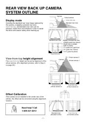
... of vehicle) 6 ft. guide line (Yellow) 1.5 ft. guide line (Light blue) 3 ft. REAR VIEW BACK UP CAMERA SYSTEM OUTLINE Display mode Including the standard rear view image captured by alignment of the virtual camera. (For alignment process, refer to Step 3 on page 20.) Standard rear view View-from -top height can be corrected using the alignment function. Call 1-800-421...
... of vehicle) 6 ft. guide line (Yellow) 1.5 ft. guide line (Light blue) 3 ft. REAR VIEW BACK UP CAMERA SYSTEM OUTLINE Display mode Including the standard rear view image captured by alignment of the virtual camera. (For alignment process, refer to Step 3 on page 20.) Standard rear view View-from -top height can be corrected using the alignment function. Call 1-800-421...

Instruction Manual
Page 21
... of the guide lines becomes narrower. Select a view-from -top height alignment is pressed, the width of the vehicle can be seen better on the screen. 3-2. Set the left /right guide lines alignment is indicated in red on the screen. ʵ20ʵ Press and hold the control switch for... more than two seconds. Left/right guide lines alignment (flashing yellow rectangle) 4-1. The right guide line is now set and the screen changes to a higher or lower view-from -top height alignment (flashing violet ...
... of the guide lines becomes narrower. Select a view-from -top height alignment is pressed, the width of the vehicle can be seen better on the screen. 3-2. Set the left /right guide lines alignment is indicated in red on the screen. ʵ20ʵ Press and hold the control switch for... more than two seconds. Left/right guide lines alignment (flashing yellow rectangle) 4-1. The right guide line is now set and the screen changes to a higher or lower view-from -top height alignment (flashing violet ...