Owners Manual
Page 2
SANYO MOBILE AUDIO MODEL FXCD-1350 LIMITED WARRANTY OBLIGATIONS In order to obtain warranty service, the product must be obtained by calling the toll-free number listed below , SANYO FISHER COMPANY(SFC) warrants this warranty. For product operation, authorized service center referral, service assistance or problem ...fill in the information below for your protection in the event of theft or loss of Authorized Sanyo Service Center may be delivered to uncrating, setup, installation, removal of the product for repair or reinstallation of Purchase Purchase Price Where Purchased WARNING : TO...
SANYO MOBILE AUDIO MODEL FXCD-1350 LIMITED WARRANTY OBLIGATIONS In order to obtain warranty service, the product must be obtained by calling the toll-free number listed below , SANYO FISHER COMPANY(SFC) warrants this warranty. For product operation, authorized service center referral, service assistance or problem ...fill in the information below for your protection in the event of theft or loss of Authorized Sanyo Service Center may be delivered to uncrating, setup, installation, removal of the product for repair or reinstallation of Purchase Purchase Price Where Purchased WARNING : TO...
Owners Manual
Page 3
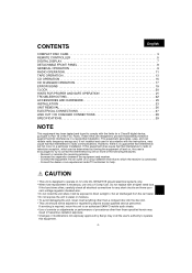
... replacement is required, return the unit to an authorized SANYO mobile audio dealer. • Use of controls or adjustments or performance of procedures other than those specified herein may result in a residential installation. This equipment generates, uses, and can be exposed to...7 DETACHABLE FRONT PANEL 8 GENERAL OPERATION 9 RADIO OPERATION 11 TAPE OPERATION 13 CD OPERATION 15 CD CHANGER OPERATION 17 ERROR SIGNS 19 CLOCK 20 HINTS FOR PROPER AND SAFE OPERATION 21 TROUBLESHOOTING 22 ACCESSORIES AND HARDWARE 23 INSTALLATION 23 UNIT REMOVAL 26 ELECTRICAL CONNECTIONS 27 LINE...
... replacement is required, return the unit to an authorized SANYO mobile audio dealer. • Use of controls or adjustments or performance of procedures other than those specified herein may result in a residential installation. This equipment generates, uses, and can be exposed to...7 DETACHABLE FRONT PANEL 8 GENERAL OPERATION 9 RADIO OPERATION 11 TAPE OPERATION 13 CD OPERATION 15 CD CHANGER OPERATION 17 ERROR SIGNS 19 CLOCK 20 HINTS FOR PROPER AND SAFE OPERATION 21 TROUBLESHOOTING 22 ACCESSORIES AND HARDWARE 23 INSTALLATION 23 UNIT REMOVAL 26 ELECTRICAL CONNECTIONS 27 LINE...

Owners Manual
Page 7
CAUTION • Install the battery with the poles facing the correct direction. • When not in an area exposed ...battery is dead, remove the battery from the remote controller becomes weakens. If battery leakage has occurred, wipe the container first, then install a new battery. CAUTIONS REGARDING REMOTE CONTROLLER • Do not leave the remote controller in use for a long period of the dashboard...the heat. (Be especially careful of time, or if the battery is swallowed, contact a doctor immediately. BATTERY INSTALLATION Install a lithium battery (CR2025) with water completely.
CAUTION • Install the battery with the poles facing the correct direction. • When not in an area exposed ...battery is dead, remove the battery from the remote controller becomes weakens. If battery leakage has occurred, wipe the container first, then install a new battery. CAUTIONS REGARDING REMOTE CONTROLLER • Do not leave the remote controller in use for a long period of the dashboard...the heat. (Be especially careful of time, or if the battery is swallowed, contact a doctor immediately. BATTERY INSTALLATION Install a lithium battery (CR2025) with water completely.
Owners Manual
Page 9
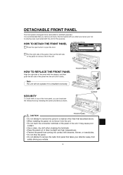
.... • When installing the panel, do not force it clicks. OPEN BUTTON 2 Pull the right side of the panel, then pull the left side of the panel into contact with the unit for antitheft purposes. FRONT PANEL SECURITY To avoid theft or loss of the panel to remove the radio front panel... that takes your car. SCREW CAUTION FRONT PANEL • Do not attempt to remove the panel in a manner other than that you remove and carry the front panel with you when you leave your attention away from safety driving you can inactivate the release knob by installing the...
.... • When installing the panel, do not force it clicks. OPEN BUTTON 2 Pull the right side of the panel, then pull the left side of the panel into contact with the unit for antitheft purposes. FRONT PANEL SECURITY To avoid theft or loss of the panel to remove the radio front panel... that takes your car. SCREW CAUTION FRONT PANEL • Do not attempt to remove the panel in a manner other than that you remove and carry the front panel with you when you leave your attention away from safety driving you can inactivate the release knob by installing the...
Owners Manual
Page 10
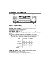
... R9 Down 0 Front F9 UP 35 SOUND EFFECT BUTTON 3 Press the SOUND Button for less than 1.5 second. GENERAL OPERATION 57 4 31 6 2 TURNING THE POWER ON 1 Install the front panel and press the POWER button when ACC is on ). bass, treble, balance, fade, or volume.
... R9 Down 0 Front F9 UP 35 SOUND EFFECT BUTTON 3 Press the SOUND Button for less than 1.5 second. GENERAL OPERATION 57 4 31 6 2 TURNING THE POWER ON 1 Install the front panel and press the POWER button when ACC is on ). bass, treble, balance, fade, or volume.
Owners Manual
Page 23
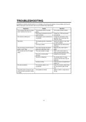
The power connections are weak. The signals are not wired correctly. Switch the ignition to the troubleshooting chart below. Install the unit securely. Insert the antenna cable firmly into the unit. Select a station using manual tuning. -22- Before having the unit serviced, refer to the ..." or "ACC" position. Symptom The compact disc does not play when inserted into the antenna jack on the unit. The sound from the CD player skips. The radio does not stop on pages 3-4. Cause The volume control is used. The fuse is dirty. The disc is blown. The antenna cable is ...
The power connections are weak. The signals are not wired correctly. Switch the ignition to the troubleshooting chart below. Install the unit securely. Insert the antenna cable firmly into the unit. Select a station using manual tuning. -22- Before having the unit serviced, refer to the ..." or "ACC" position. Symptom The compact disc does not play when inserted into the antenna jack on the unit. The sound from the CD player skips. The radio does not stop on pages 3-4. Cause The volume control is used. The fuse is dirty. The disc is blown. The antenna cable is ...
Owners Manual
Page 24
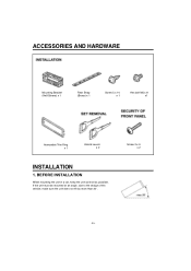
If the unit must be mounted at an angle, due to the design of the vehicle, make sure the unit does not tilt by more than 30°. BEFORE INSTALLATION When mounting the unit in a car, keep the unit as level as possible. Screw 2 x 6 x 2 -23- ACCESSORIES AND HARDWARE Mounting Bracket (Half Sleeve) x 1 Rear Strap (Brace) x 1 Screw 5 x 14 x 1 Hex bolt M5 x 8 x1 Removable Trim Ring x 1 Unlock Levers x 2 INSTALLATION 1.
If the unit must be mounted at an angle, due to the design of the vehicle, make sure the unit does not tilt by more than 30°. BEFORE INSTALLATION When mounting the unit in a car, keep the unit as level as possible. Screw 2 x 6 x 2 -23- ACCESSORIES AND HARDWARE Mounting Bracket (Half Sleeve) x 1 Rear Strap (Brace) x 1 Screw 5 x 14 x 1 Hex bolt M5 x 8 x1 Removable Trim Ring x 1 Unlock Levers x 2 INSTALLATION 1.

Owners Manual
Page 25
... the cutout. 3. ISO MOUNTING WITH REMOVABLE TRIM RING When mounting the unit into a DIN-standard cutout (182 × 53 mm) in the dashboard or console. 2. INSTALLATION PROCEDURES 5 x 14 HEX BOLT 182 mm REAR STRAP 53 mm (BRACE) DASHBOARD OR CONSOLE MOUNTING BRACKET (HALF SLEEVE) AUDIO UNIT REMOVABLE TRIM RING 1. Push the...
... the cutout. 3. ISO MOUNTING WITH REMOVABLE TRIM RING When mounting the unit into a DIN-standard cutout (182 × 53 mm) in the dashboard or console. 2. INSTALLATION PROCEDURES 5 x 14 HEX BOLT 182 mm REAR STRAP 53 mm (BRACE) DASHBOARD OR CONSOLE MOUNTING BRACKET (HALF SLEEVE) AUDIO UNIT REMOVABLE TRIM RING 1. Push the...

Owners Manual
Page 26
Use "T" holes for Toyota vehicles and "N" holes for Nissan vehicles. USE OF ANY OTHER SCREW OR HARDWARE MAY RESULT DAMAGE TO HEAD UNIT. -25- "T" or "N" is engraved next to TOYOTA/NISSAN Vehicles Install the unit using the existing TOYOTA/NISSAN Mounting Bracket and Screws. 4. TOYOTA/NISSAN Mounting Bracket Screw Screw CAUTION ONLY USE M5 x 6 SCREW (NOT INCLUDED WITH THIS UNIT) AS ILLUSTRATED ABOVE. Use mounting holes in the unit chassis. Installation to each mounting hole.
Use "T" holes for Toyota vehicles and "N" holes for Nissan vehicles. USE OF ANY OTHER SCREW OR HARDWARE MAY RESULT DAMAGE TO HEAD UNIT. -25- "T" or "N" is engraved next to TOYOTA/NISSAN Vehicles Install the unit using the existing TOYOTA/NISSAN Mounting Bracket and Screws. 4. TOYOTA/NISSAN Mounting Bracket Screw Screw CAUTION ONLY USE M5 x 6 SCREW (NOT INCLUDED WITH THIS UNIT) AS ILLUSTRATED ABOVE. Use mounting holes in the unit chassis. Installation to each mounting hole.
Owners Manual
Page 28
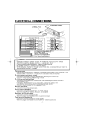
... floating. • When wiring the amplifier for the sub-woofer, noise may occur depending on where the ground (earth) terminal is installed. 1 Antenna socket • Insert the plug from the antenna installed in your vehicle into this socket. (If your vehicle has a dual antenna system, a dual antenna to single antenna cable adaptor...
... floating. • When wiring the amplifier for the sub-woofer, noise may occur depending on where the ground (earth) terminal is installed. 1 Antenna socket • Insert the plug from the antenna installed in your vehicle into this socket. (If your vehicle has a dual antenna system, a dual antenna to single antenna cable adaptor...
Owners Manual
Page 29
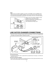
...are used for a four-speaker installation, are not used. Fuse 15A NG OK Burnt LINE OUT/CD CHANGER CONNECTIONS • The unit has a built-in CD changer controller and line output terminals. The ends of these wires must be covered with the compatible Sanyo CD changer, to upgrade your system.... fuse. Then install the new 15 amp. You can use a compatible Sanyo CD changer and a separate amplifier to the DIN socket on the back of the external amplifier...
...are used for a four-speaker installation, are not used. Fuse 15A NG OK Burnt LINE OUT/CD CHANGER CONNECTIONS • The unit has a built-in CD changer controller and line output terminals. The ends of these wires must be covered with the compatible Sanyo CD changer, to upgrade your system.... fuse. Then install the new 15 amp. You can use a compatible Sanyo CD changer and a separate amplifier to the DIN socket on the back of the external amplifier...