
Product Manual
Page 5
C iii commands 47 5.0 Seagate Technology support services 49 Barracuda 7200.9 PATA Product Manual, Rev. Contents 1.0 Introduction 1 2.0 Drive specifications 3 2.1 Specification summary table 3 2.2 Formatted capacity 18 2.2.1 LBA mode 18 2.3 Default logical geometry 18 2.4...35 3.3.2 Cable-select option 35 3.3.3 Alternate capacity jumper 35 3.3.4 Ultra ATA/100 cable 36 3.4 Drive mounting 36 4.0 ATA interface 39 4.1 ATA interface signals and connector pins 39 4.1.1 Supported ATA commands 40 4.1.2 Identify Device command 42 4.1.3 Set Features command 46 4.1.4 S.M.A.R.T.
C iii commands 47 5.0 Seagate Technology support services 49 Barracuda 7200.9 PATA Product Manual, Rev. Contents 1.0 Introduction 1 2.0 Drive specifications 3 2.1 Specification summary table 3 2.2 Formatted capacity 18 2.2.1 LBA mode 18 2.3 Default logical geometry 18 2.4...35 3.3.2 Cable-select option 35 3.3.3 Alternate capacity jumper 35 3.3.4 Ultra ATA/100 cable 36 3.4 Drive mounting 36 4.0 ATA interface 39 4.1 ATA interface signals and connector pins 39 4.1.1 Supported ATA commands 40 4.1.2 Identify Device command 42 4.1.3 Set Features command 46 4.1.4 S.M.A.R.T.

Product Manual
Page 7
Figure 3. Figure 5. Figure 2. Figure 4. Figure 7. Typical 5V startup and operation current profile 23 Typical 12V startup and operation current profile 23 Breather filter hole location 34 Master/slave jumper settings 35 Ultra ATA cable connectors 36 Mounting dimensions-top, side and end view 37 I/O pins and supported ATA signals 39 Barracuda 7200.9 PATA Product Manual, Rev. C v Figure 6. List of Figures Figure 1.
Figure 3. Figure 5. Figure 2. Figure 4. Figure 7. Typical 5V startup and operation current profile 23 Typical 12V startup and operation current profile 23 Breather filter hole location 34 Master/slave jumper settings 35 Ultra ATA cable connectors 36 Mounting dimensions-top, side and end view 37 I/O pins and supported ATA signals 39 Barracuda 7200.9 PATA Product Manual, Rev. C v Figure 6. List of Figures Figure 1.

Product Manual
Page 29
...latency time. This mode is not typical and is provided for the drives are active. Barracuda 7200.9 PATA Product Manual, Rev. 2.8 Power specifications The drive receives DC power (+5V or +12V) through a four-pin standard drive power connector. 2.8.1 Power consumption Power requirements for worst-case information. ... seeks with the heads in a random track location. • Standby mode During Standby mode, the drive accepts commands, but the drive is measured from the time of drives tested, under nominal conditions, using +5.0V and +12.0V input voltage at 25°C ambient temperature...
...latency time. This mode is not typical and is provided for the drives are active. Barracuda 7200.9 PATA Product Manual, Rev. 2.8 Power specifications The drive receives DC power (+5V or +12V) through a four-pin standard drive power connector. 2.8.1 Power consumption Power requirements for worst-case information. ... seeks with the heads in a random track location. • Standby mode During Standby mode, the drive accepts commands, but the drive is measured from the time of drives tested, under nominal conditions, using +5.0V and +12.0V input voltage at 25°C ambient temperature...

Product Manual
Page 41
... a grounded wrist strap, or ground yourself frequently by its edges or frame only. • The drive is plugged into a grounded outlet. Barracuda 7200.9 PATA Product Manual, Rev. Some factory-installed labels contain information needed to seal out dirt and contamination. Wear a grounded... in the computer. • Do not touch the connector pins or the printed circuit board. • Do not remove the factory-installed labels from the drive or cover them with care. 3.0 Configuring and mounting the drive This section contains the specifications and instructions for configuring and mounting...
... a grounded wrist strap, or ground yourself frequently by its edges or frame only. • The drive is plugged into a grounded outlet. Barracuda 7200.9 PATA Product Manual, Rev. Some factory-installed labels contain information needed to seal out dirt and contamination. Wear a grounded... in the computer. • Do not touch the connector pins or the printed circuit board. • Do not remove the factory-installed labels from the drive or cover them with care. 3.0 Configuring and mounting the drive This section contains the specifications and instructions for configuring and mounting...

Product Manual
Page 43
... computers may "hang" at the factory for a master or single-drive operation with no jumpers installed. To enable cable select, set on pins 5 and 6 as a master or a slave. Barracuda 7200.9 PATA Product Manual, Rev. Remove all jumpers. Drive as a master with a jumper set a jumper on pins 7 and 8. Refer to your computer manual to determine whether...
... computers may "hang" at the factory for a master or single-drive operation with no jumpers installed. To enable cable select, set on pins 5 and 6 as a master or a slave. Barracuda 7200.9 PATA Product Manual, Rev. Remove all jumpers. Drive as a master with a jumper set a jumper on pins 7 and 8. Refer to your computer manual to determine whether...
Product Manual
Page 44
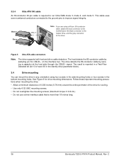
... inches long. 36 Barracuda 7200.9 PATA Product Manual, Rev. Follow these important mounting precautions when mounting the drive: • Allow a minimum clearance of 0.030 inches (0.76 mm) around the entire perimeter of word 93 in the Identify drive parameter block). 3.4 Drive mounting You can mount the drive in any orientation using a 40-pin, 80-conductor cable...
... inches long. 36 Barracuda 7200.9 PATA Product Manual, Rev. Follow these important mounting precautions when mounting the drive: • Allow a minimum clearance of 0.030 inches (0.76 mm) around the entire perimeter of word 93 in the Identify drive parameter block). 3.4 Drive mounting You can mount the drive in any orientation using a 40-pin, 80-conductor cable...
Product Manual
Page 47
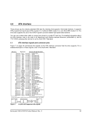
... AT host bus. HDMARDY- DSTROBE CSEL DMACK- DA0 DA2 CS0- DA1 PDIAG- C 39 For a detailed description of the IORDY signal to the Draft ATA-7 Standard. Drive pin # 1 2 3 4 5 6 7 8 9 10 11 12 13 14 15 16 17 18 19 20 21 22 23 24 25 26 27 28 29 30...Read: Host Ultra DMA Ready: Host Ultra DMA Data Strobe 26 Ground 27 I /O pins and supported ATA signals Barracuda 7200.9 PATA Product Manual, Rev. 4.0 ATA interface These drives use the industry-standard ATA task file interface that the drive supports. DASP- multiword DMA modes 0-2, and Ultra DMA modes 0-5. It supports ATA ...
... AT host bus. HDMARDY- DSTROBE CSEL DMACK- DA0 DA2 CS0- DA1 PDIAG- C 39 For a detailed description of the IORDY signal to the Draft ATA-7 Standard. Drive pin # 1 2 3 4 5 6 7 8 9 10 11 12 13 14 15 16 17 18 19 20 21 22 23 24 25 26 27 28 29 30...Read: Host Ultra DMA Ready: Host Ultra DMA Data Strobe 26 Ground 27 I /O pins and supported ATA signals Barracuda 7200.9 PATA Product Manual, Rev. 4.0 ATA interface These drives use the industry-standard ATA task file interface that the drive supports. DASP- multiword DMA modes 0-2, and Ultra DMA modes 0-5. It supports ATA ...
Product Manual
Page 63
... Power Mode 40 commands 40 compliance 29 conducted noise 24 conducted RF immunity 28 configuring the drive 33 connector pins 39 connectors 36 contact start-stop cycles 29 Corrosive environment 31 CSA C22.2 (950) 29...40 diagnostic software 1, 47 DiscWizard 35 Disk Manager 35 dissipation 22, 23 Download Microcode 40 drive diagnostics 20 drive monitoring 1 drive self-test 1, 47 DST 47 E electrical fast transient 28 electromagnetic compatibility 29 Electromagnetic Compatibility ...height 20 humidity 25 I I/O data-transfer rate 19 Identify Device 40 Barracuda 7200.9 PATA Product Manual, Rev. C 55
... Power Mode 40 commands 40 compliance 29 conducted noise 24 conducted RF immunity 28 configuring the drive 33 connector pins 39 connectors 36 contact start-stop cycles 29 Corrosive environment 31 CSA C22.2 (950) 29...40 diagnostic software 1, 47 DiscWizard 35 Disk Manager 35 dissipation 22, 23 Download Microcode 40 drive diagnostics 20 drive monitoring 1 drive self-test 1, 47 DST 47 E electrical fast transient 28 electromagnetic compatibility 29 Electromagnetic Compatibility ...height 20 humidity 25 I I/O data-transfer rate 19 Identify Device 40 Barracuda 7200.9 PATA Product Manual, Rev. C 55
Product Manual
Page 64
... 35 master/slave 1 Master/slave configuration 35 maximum temperature 25 measurement locations 25 modes 39 monitoring 1 mounting the drive 33, 36 N noise 24 nominal power 3 nonoperating shock 26 nonoperating vibration 26 nonrecoverable read errors 29 O operating... operating power and current 21 operating shock 26 operating vibration 26 orientation 36 56 P physical characteristics 20 pins 39 PIO 39 power consumption 21 power dissipation 22, 23 power management 24 power specifications 21 power-management... resistance 24 resistive load 24 RF 28 RoHS 31 Barracuda 7200.9 PATA Product Manual, Rev. C
... 35 master/slave 1 Master/slave configuration 35 maximum temperature 25 measurement locations 25 modes 39 monitoring 1 mounting the drive 33, 36 N noise 24 nominal power 3 nonoperating shock 26 nonoperating vibration 26 nonrecoverable read errors 29 O operating... operating power and current 21 operating shock 26 operating vibration 26 orientation 36 56 P physical characteristics 20 pins 39 PIO 39 power consumption 21 power dissipation 22, 23 power management 24 power specifications 21 power-management... resistance 24 resistive load 24 RF 28 RoHS 31 Barracuda 7200.9 PATA Product Manual, Rev. C

