
Instructions for Use
Page 1
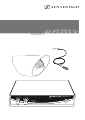
Industry Acoustic System IAS-MO 2000 Set Instructions for use 0 20 40 +/- 15dB 0 dB GAIN LEVEL OVERLOAD
Industry Acoustic System IAS-MO 2000 Set Instructions for use 0 20 40 +/- 15dB 0 dB GAIN LEVEL OVERLOAD
Instructions for Use
Page 3
Contents Safety instructions...2 IAS-MO 2000 Set ...4 Delivery includes...5 IAS-MO 2000 Set 5 MZWW 2000 ...5 Product overview IAS-MO 2000 Set 6 Putting the system into operation 7 Setting up the device 7 Rack mounting ...7 Connecting the mains unit 8 Connecting the amplifier 8 Connecting the optical microphone 9 Switching the central unit on/off 11 Adjusting the sensitivity 11 Overload indication 11 Disassembling the weather and wind protection 12 Accessories...12 Care and maintenance 13 Specifications ...14 Connector assignment 15 Frequency response curve 15 Manufacturer ...
Contents Safety instructions...2 IAS-MO 2000 Set ...4 Delivery includes...5 IAS-MO 2000 Set 5 MZWW 2000 ...5 Product overview IAS-MO 2000 Set 6 Putting the system into operation 7 Setting up the device 7 Rack mounting ...7 Connecting the mains unit 8 Connecting the amplifier 8 Connecting the optical microphone 9 Switching the central unit on/off 11 Adjusting the sensitivity 11 Overload indication 11 Disassembling the weather and wind protection 12 Accessories...12 Care and maintenance 13 Specifications ...14 Connector assignment 15 Frequency response curve 15 Manufacturer ...
Instructions for Use
Page 4
... plugged into the wall socket, - only operated within the rack must be installed and operated outside areas with potentially explosive atmospheres! 0044 Use of time. To meet the requirement of the ATEX directive, the central unit must not exceed the temperature limit specified in a safe place. When installing the device in the MZWW 2000 weather and wind protection, the MO 2000 H optical microphone meets...
... plugged into the wall socket, - only operated within the rack must be installed and operated outside areas with potentially explosive atmospheres! 0044 Use of time. To meet the requirement of the ATEX directive, the central unit must not exceed the temperature limit specified in a safe place. When installing the device in the MZWW 2000 weather and wind protection, the MO 2000 H optical microphone meets...
Instructions for Use
Page 5
.... "Improper use attachments/accessories specified by customers in breach of this device as mains cable or plug damage, liquid has been spilled, objects have it checked by a technician. Keep the device away from direct sunlight and similar sources of heat. Only use " means using the device other hazards. Refer all servicing to rain or moisture, does not operate properly...
.... "Improper use attachments/accessories specified by customers in breach of this device as mains cable or plug damage, liquid has been spilled, objects have it checked by a technician. Keep the device away from direct sunlight and similar sources of heat. Only use " means using the device other hazards. Refer all servicing to rain or moisture, does not operate properly...
Instructions for Use
Page 6
... an external wide voltage range power supply unit. Power is connected to be found in areas where aggressive substances (gases, salts, moisture) or radiation are made of plastic suitable for picking up airborne sound. The MO 2000 H is fitted with a fixed 3 m double fiber optic cable. The components of non-detectable acoustic surveillance. 4 The main areas of application of an opto-acoustic microphone...
... an external wide voltage range power supply unit. Power is connected to be found in areas where aggressive substances (gases, salts, moisture) or radiation are made of plastic suitable for picking up airborne sound. The MO 2000 H is fitted with a fixed 3 m double fiber optic cable. The components of non-detectable acoustic surveillance. 4 The main areas of application of an opto-acoustic microphone...
Instructions for Use
Page 7
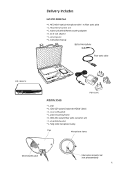
Delivery includes IAS-MO 2000 Set y 1 MO 2000 H optical microphone with 3 m fiber optic cable y 1 MO 2000 CU central unit y 1 mains unit with different country adapters y 1 GA 2 rack adapter y 1 carrying case y 1 instruction manual Optical microphone Fiber optic cable MO 2000 CU 0 20 40 +/- 15dB 0 dB GAIN LEVEL OVERLOAD Mains unit MZWW 2000 y 1 pipe y 1 SCRJ-GOF socket (inside the MZWW 2000) y 1 cover with gasket y 1 plate/mounting frame y 1 SCRJ-HCS socket (fiber optic connector set) y 1 windshield basket y 1 MZQ 2000 microphone clamp Pipe...
Delivery includes IAS-MO 2000 Set y 1 MO 2000 H optical microphone with 3 m fiber optic cable y 1 MO 2000 CU central unit y 1 mains unit with different country adapters y 1 GA 2 rack adapter y 1 carrying case y 1 instruction manual Optical microphone Fiber optic cable MO 2000 CU 0 20 40 +/- 15dB 0 dB GAIN LEVEL OVERLOAD Mains unit MZWW 2000 y 1 pipe y 1 SCRJ-GOF socket (inside the MZWW 2000) y 1 cover with gasket y 1 plate/mounting frame y 1 SCRJ-HCS socket (fiber optic connector set) y 1 windshield basket y 1 MZQ 2000 microphone clamp Pipe...
Instructions for Use
Page 8
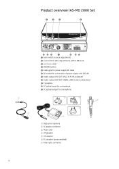
.../OFF button ´ Cable grip for power supply DC cable ² DC socket for connection of power supply unit (DC IN) ¶ Audio output (AF OUT BAL), XLR-3M, balanced º Audio output (AF OUT UNBAL), BNC socket, unbalanced ¾ Type plate µ SC optical input for microphone ¸ SC optical output for microphone 4 5 7 6 3 ቢ Optical microphone ባ SC duplex connector ቤ Mains unit ብ US adapter ቦ UK adapter ቧ EU adapter...
.../OFF button ´ Cable grip for power supply DC cable ² DC socket for connection of power supply unit (DC IN) ¶ Audio output (AF OUT BAL), XLR-3M, balanced º Audio output (AF OUT UNBAL), BNC socket, unbalanced ¾ Type plate µ SC optical input for microphone ¸ SC optical output for microphone 4 5 7 6 3 ቢ Optical microphone ባ SC duplex connector ቤ Mains unit ብ US adapter ቦ UK adapter ቧ EU adapter...

Instructions for Use
Page 9
... the base of staining. ̈ Do not place the central unit on which might cause stains when they come into operation CAUTION! Setting up the device on an even surface or mount it is clean and free from grease before fitting the rubber feet. ̈ Fix the...rack assembly, please note that , during operation, the temperature within the rack may accumulate, thereby exceeding the allowable limit value. ̈ Ground the rack via an additional ground connection. Some furniture surfaces have been treated with other synthetics. When installing the device in a closed or multi-...
... the base of staining. ̈ Do not place the central unit on which might cause stains when they come into operation CAUTION! Setting up the device on an even surface or mount it is clean and free from grease before fitting the rubber feet. ̈ Fix the...rack assembly, please note that , during operation, the temperature within the rack may accumulate, thereby exceeding the allowable limit value. ̈ Ground the rack via an additional ground connection. Some furniture surfaces have been treated with other synthetics. When installing the device in a closed or multi-...
Instructions for Use
Page 10
.... Use the cable grip ᕥ to secure the power supply DC cable. ̈ Connect the suitable adapter to the mains unit ቤ. ̈ Connect the mains unit ቤ to the socket ᕦ (DC IN). For details on balanced or unbalanced connection, see "Connector assignment" on automatically. To mount two central units into the 19" rack. ̈ Secure the rack mount "ears" to the rack. Both outputs...
.... Use the cable grip ᕥ to secure the power supply DC cable. ̈ Connect the suitable adapter to the mains unit ቤ. ̈ Connect the mains unit ቤ to the socket ᕦ (DC IN). For details on balanced or unbalanced connection, see "Connector assignment" on automatically. To mount two central units into the 19" rack. ̈ Secure the rack mount "ears" to the rack. Both outputs...
Instructions for Use
Page 11
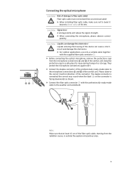
... supplied fiber optic connector ቨ. ̈ Before connecting the optical microphone, remove the protections caps from the radiation source, is outside the explosion-hazardous area. 9 Signal loss! Please observe the correct insertion direction of damage to the weather and windshield. ³ ³ 7 · Note: Make sure that at least 15 cm of the fiber optic cable, starting from the microphone connections...
... supplied fiber optic connector ቨ. ̈ Before connecting the optical microphone, remove the protections caps from the radiation source, is outside the explosion-hazardous area. 9 Signal loss! Please observe the correct insertion direction of damage to the weather and windshield. ³ ³ 7 · Note: Make sure that at least 15 cm of the fiber optic cable, starting from the microphone connections...
Instructions for Use
Page 12
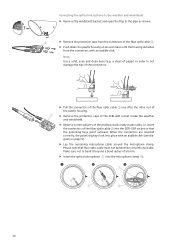
... Use a solid, even and clean base (e.g. Please note that the polarizing keys point outward. insert the connectors of the fiber optic cable ባ into place with an audible click (see diagram on an even base until the housing detaches from the connectors of the fiber optic cable ...the protection caps from the connectors with an audible click. When the connectors are inserted correctly, the polarizing keys lock into the SCRJ-GOF socket so that fiber optic cable must not be bent like conventional cable. Connecting the optical microphone to the weather and windshield ̈ Remove ...
... Use a solid, even and clean base (e.g. Please note that the polarizing keys point outward. insert the connectors of the fiber optic cable ባ into place with an audible click (see diagram on an even base until the housing detaches from the connectors of the fiber optic cable ...the protection caps from the connectors with an audible click. When the connectors are inserted correctly, the polarizing keys lock into the SCRJ-GOF socket so that fiber optic cable must not be bent like conventional cable. Connecting the optical microphone to the weather and windshield ̈ Remove ...
Instructions for Use
Page 13
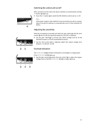
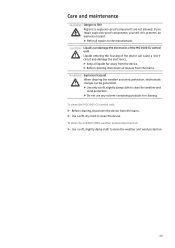
... » lights up: ̈ Use the gain control ᕡ and/or the level control ᕢ to reduce the output voltage level so that the OVERLOAD LED » no longer lights up . ̈ Press the ON button ᕤ to a power failure), the device switches on or off before. Adjusting the sensitivity 0 20 40 +/- 15dB 0 dB GAIN LEVEL OVERLOAD With the microphone connected and...
... » lights up: ̈ Use the gain control ᕡ and/or the level control ᕢ to reduce the output voltage level so that the OVERLOAD LED » no longer lights up . ̈ Press the ON button ᕤ to a power failure), the device switches on or off before. Adjusting the sensitivity 0 20 40 +/- 15dB 0 dB GAIN LEVEL OVERLOAD With the microphone connected and...
Instructions for Use
Page 14
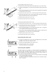
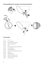
Disassembling the weather and wind protection 1 22 3 4 7 6 5 Accessories Cat.-No. 009823 525700 525701 525702 522170 522168 522169 522176 067510 524601 502186 511999 516503 Accessory GA 2 rack adapter MO 2000 H optical microphone MO 2000 CU central unit Pipe SCRJ-GOF socket (inside the MZWW 2000) Cover with gasket Plate/mounting frame SCRJ-HCS socket (fiber optic connector set) Mains unit Windshield basket MZQ 2000 microphone clamp Carrying case with foam insert Instruction manual 12
Disassembling the weather and wind protection 1 22 3 4 7 6 5 Accessories Cat.-No. 009823 525700 525701 525702 522170 522168 522169 522176 067510 524601 502186 511999 516503 Accessory GA 2 rack adapter MO 2000 H optical microphone MO 2000 CU central unit Pipe SCRJ-GOF socket (inside the MZWW 2000) Cover with gasket Plate/mounting frame SCRJ-HCS socket (fiber optic connector set) Mains unit Windshield basket MZQ 2000 microphone clamp Carrying case with foam insert Instruction manual 12
Instructions for Use
Page 15
...weather and wind protection. ̈ Do not use any solvent-containing products for cleaning. If you repair explosion-proof components yourself, this presents an explosion hazard. ̈ Refer all devices from the mains. ̈ Use a soft, dry cloth to the manufacturer. Explosion hazard! Care and maintenance WARNING! CAUTION! WARNING! To clean the MO 2000 CU central unit...: ̈ Before cleaning, disconnect the device from the mains. Liquids can be generated. ̈ Use only a soft, slightly damp cloth to clean the weather and wind protection....
...weather and wind protection. ̈ Do not use any solvent-containing products for cleaning. If you repair explosion-proof components yourself, this presents an explosion hazard. ̈ Refer all devices from the mains. ̈ Use a soft, dry cloth to the manufacturer. Explosion hazard! Care and maintenance WARNING! CAUTION! WARNING! To clean the MO 2000 CU central unit...: ̈ Before cleaning, disconnect the device from the mains. Liquids can be generated. ̈ Use only a soft, slightly damp cloth to clean the weather and wind protection....
Instructions for Use
Page 16
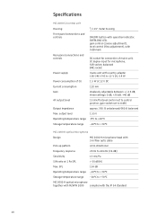
...) Output impedance approx. 330 Ω unbalanced/660 Ω balanced Max. Specifications MO 2000 CU central unit Housing 1/2 19" metal housing Front panel connections and controls ON/OFF button with operation indicator, OVERLOAD LED, gain control (coarse adjustment), level control (fine adjustment), with 0 dB mark Rear panel connections and controls DC socket for connection of mains unit, SC duplex input for microphone, XLR socket, balanced BNC socket Power supply mains unit with country adapter...
...) Output impedance approx. 330 Ω unbalanced/660 Ω balanced Max. Specifications MO 2000 CU central unit Housing 1/2 19" metal housing Front panel connections and controls ON/OFF button with operation indicator, OVERLOAD LED, gain control (coarse adjustment), level control (fine adjustment), with 0 dB mark Rear panel connections and controls DC socket for connection of mains unit, SC duplex input for microphone, XLR socket, balanced BNC socket Power supply mains unit with country adapter...
Instructions for Use
Page 17
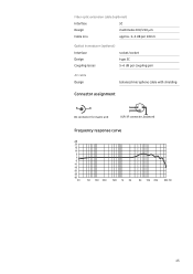
Fiber optic extension cable (optional) Interface SC Design multimode 200/230 μm Cable loss approx. 3-4 dB per 100 m Optical transducer (optional) Interface socket/socket Design type SC Coupling losses 5-6 dB per coupling pair AF cable Design balanced microphone cable with shielding Connector assignment DC connector for mains unit + 21 3 XLR-3F connector, balanced Frequency response curve dB 20 15 10 5 0 -5 -10 -15 -20 -25 -30 20 50 100 200 500 1k 2k 5k 10k 20k 50k Hz 15
Fiber optic extension cable (optional) Interface SC Design multimode 200/230 μm Cable loss approx. 3-4 dB per 100 m Optical transducer (optional) Interface socket/socket Design type SC Coupling losses 5-6 dB per coupling pair AF cable Design balanced microphone cable with shielding Connector assignment DC connector for mains unit + 21 3 XLR-3F connector, balanced Frequency response curve dB 20 15 10 5 0 -5 -10 -15 -20 -25 -30 20 50 100 200 500 1k 2k 5k 10k 20k 50k Hz 15
Instructions for Use
Page 18
...Part 15 of the FCC Rules and with the essential requirements and other relevant provisions of Directives 94/9/EC, 2004/108/EC, and 2006/95/EC. CE Declaration of Conformity 0044 This equipment is subject to EN 60079-0: 2004 and EN 60079-28:2007. Changes or modifications made to operate...may cause undesired operation. For the current warranty conditions, please visit our web site at www.sennheiser.com or contact your Sennheiser partner. The IAS MO 2000 Set microphone system complies with the requirements on this device must accept any interference received, including interference ...
...Part 15 of the FCC Rules and with the essential requirements and other relevant provisions of Directives 94/9/EC, 2004/108/EC, and 2006/95/EC. CE Declaration of Conformity 0044 This equipment is subject to EN 60079-0: 2004 and EN 60079-28:2007. Changes or modifications made to operate...may cause undesired operation. For the current warranty conditions, please visit our web site at www.sennheiser.com or contact your Sennheiser partner. The IAS MO 2000 Set microphone system complies with the requirements on this device must accept any interference received, including interference ...

Instructions for Use
Page 20
Sennheiser electronic GmbH & Co. KG Am Labor 1 30900 Wedemark, Germany Phone +49 (5130) 600 0 Fax +49 (5130) 600 300 www.sennheiser.com Printed in Germany Publ. 08/08 524194/A01
Sennheiser electronic GmbH & Co. KG Am Labor 1 30900 Wedemark, Germany Phone +49 (5130) 600 0 Fax +49 (5130) 600 300 www.sennheiser.com Printed in Germany Publ. 08/08 524194/A01

