

Service Manual
Page 1
... set should be restored to its original condition and only parts identical to be used for maintaining the safety and performance of the set. ADJUSTMENTS [1] Mechanism Section 2-1 [2] Test Mode 2-2 [3] CD Section 2-4 [4] CD Changer Mechanism Section 2-5 CHAPTER 3. DIAGRAMS [1] Main Block Diagrams 4-1 [2] CD Block Diagrams 4-3 CHAPTER 5. SHARP CORPORATION This document has been published to those specified be used. S3715CDSW330/ MINI COMPONENT SYSTEM MODEL CD-SW330 CD-SW330 Mini Component System consisting of XM® Satellite Radio Inc. CD-SW330 SERVICE MANUAL...
... set should be restored to its original condition and only parts identical to be used for maintaining the safety and performance of the set. ADJUSTMENTS [1] Mechanism Section 2-1 [2] Test Mode 2-2 [3] CD Section 2-4 [4] CD Changer Mechanism Section 2-5 CHAPTER 3. DIAGRAMS [1] Main Block Diagrams 4-1 [2] CD Block Diagrams 4-3 CHAPTER 5. SHARP CORPORATION This document has been published to those specified be used. S3715CDSW330/ MINI COMPONENT SYSTEM MODEL CD-SW330 CD-SW330 Mini Component System consisting of XM® Satellite Radio Inc. CD-SW330 SERVICE MANUAL...

Service Manual
Page 2
...-free wire solder or soldering bit, contact our service station or service branch in contact with lead-free solder. Clean the bit after every use a dedicated soldering bit, if you are not familiar with polarity indication on the PWB and service manuals. Employing lead-free solder "MAIN, POWER, DISPLAY, GAME INPUT, CD MP3, FRONT SPEAKER LED, XM READY, CD CHANGER MOTOR (PWB ONLY), SUB WOOFER LED " of lead-free...
...-free wire solder or soldering bit, contact our service station or service branch in contact with lead-free solder. Clean the bit after every use a dedicated soldering bit, if you are not familiar with polarity indication on the PWB and service manuals. Employing lead-free solder "MAIN, POWER, DISPLAY, GAME INPUT, CD MP3, FRONT SPEAKER LED, XM READY, CD CHANGER MOTOR (PWB ONLY), SUB WOOFER LED " of lead-free...

Service Manual
Page 3
... CD-SW330 [1] Important Service Safety Precaution CAUTION : "These servicing instructions are for U.S.A only) BEFORE RETURNING THE AUDIO PRODUCT (Fire & Shock Hazard) Before returning the audio product to the user, perform the following manner. * Plug the AC line cord directly into a 120 volt AC outlet. * Using two clip leads, connect a 1.5k ohm, 10 watt resistor paralleled by qualified service personnel only. CAUTION: FOR CONTINUED PROTECTION AGAINST FIRE HAZARD, REPLACE...
... CD-SW330 [1] Important Service Safety Precaution CAUTION : "These servicing instructions are for U.S.A only) BEFORE RETURNING THE AUDIO PRODUCT (Fire & Shock Hazard) Before returning the audio product to the user, perform the following manner. * Plug the AC line cord directly into a 120 volt AC outlet. * Using two clip leads, connect a 1.5k ohm, 10 watt resistor paralleled by qualified service personnel only. CAUTION: FOR CONTINUED PROTECTION AGAINST FIRE HAZARD, REPLACE...

Service Manual
Page 4
... harmonic distortion. Front Speakers: 6 ohms Subwoofer: 12 ohms Headphones: 16 - 50 ohms (recommended: 32 ohms) Video output: 1Vp-p Game/Auxiliary (audio signal): 500 mV/ 47 k ohms Game/Video: 1Vp-p CD player Type Signal readout D/A converter Frequency response Dynamic range 5-disc multi-play compact disc player Non-contact, 3-beam semiconductor laser pickup Multi bit D/A converter 20 - 20,000 Hz 90 dB (1 kHz) Tuner Frequency range FM: 87.5 - 108.0 MHz AM: 530 - 1,720 kHz Cassette deck Frequency response Signal/noise ratio Wow...
... harmonic distortion. Front Speakers: 6 ohms Subwoofer: 12 ohms Headphones: 16 - 50 ohms (recommended: 32 ohms) Video output: 1Vp-p Game/Auxiliary (audio signal): 500 mV/ 47 k ohms Game/Video: 1Vp-p CD player Type Signal readout D/A converter Frequency response Dynamic range 5-disc multi-play compact disc player Non-contact, 3-beam semiconductor laser pickup Multi bit D/A converter 20 - 20,000 Hz 90 dB (1 kHz) Tuner Frequency range FM: 87.5 - 108.0 MHz AM: 530 - 1,720 kHz Cassette deck Frequency response Signal/noise ratio Wow...
Service Manual
Page 5
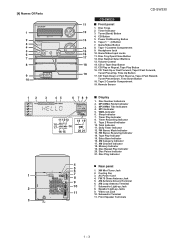
...10. Disc Number Select Buttons 13. FM Stereo Mode Indicator 13. XM Category Indicator 17. Disc Pause Indicator 21. AC Power Cord 4. Tape 1 Cassette Compartment 9. CD Play or Repeat, Tape Play Button 16. Disc Number Indicators 2. Total Indicator 11. AM Loop Antenna Terminal 10 7. Subwoofer Terminal 11. Disc Trays 2. Game/Video Input Jacks 11. Volume Control 14. Tape 2 Record Indicator 10. Tape Play Indicator 15. Disc Play Indicator 4 5 Rear panel 6 1. Video out Jack 10. MP3 Indicator 5. Cooling Fan 8 3. Subwoofer Light-up Jacks 11 9. Front Speaker...
...10. Disc Number Select Buttons 13. FM Stereo Mode Indicator 13. XM Category Indicator 17. Disc Pause Indicator 21. AC Power Cord 4. Tape 1 Cassette Compartment 9. CD Play or Repeat, Tape Play Button 16. Disc Number Indicators 2. Total Indicator 11. AM Loop Antenna Terminal 10 7. Subwoofer Terminal 11. Disc Trays 2. Game/Video Input Jacks 11. Volume Control 14. Tape 2 Record Indicator 10. Tape Play Indicator 15. Disc Play Indicator 4 5 Rear panel 6 1. Video out Jack 10. MP3 Indicator 5. Cooling Fan 8 3. Subwoofer Light-up Jacks 11 9. Front Speaker...

Service Manual
Page 6
... Button 11. Tape Play Button 21. Folder Button 28. XM Display Button CP-S330 Front Speaker 1. Super Tweeter 3. Disc Stop Button 16. MP3/WMA Display Button 27. XM Menu Button 29. Speaker Wire 3 4 1 - 43 Remote Control Transmitter 2. Disc Random Button 15. Tweeter 2. Woofer 4. Bass Reflex Duct 3. Disc Number Select Buttons 3. Game/Video Button 13. Bass Reflex Duct 5. Speaker Light-Up Wire CP-SW330 Subwoofer 1. Disc Track Up or Fast Forward, Tape Fast Forward, Tuner Preset Up, Time Up, Cursor Right Button 24. Power On/Stand-by Button 9. Clear/Dimmer Button 14. CD-SW330...
... Button 11. Tape Play Button 21. Folder Button 28. XM Display Button CP-S330 Front Speaker 1. Super Tweeter 3. Disc Stop Button 16. MP3/WMA Display Button 27. XM Menu Button 29. Speaker Wire 3 4 1 - 43 Remote Control Transmitter 2. Disc Random Button 15. Tweeter 2. Woofer 4. Bass Reflex Duct 3. Disc Number Select Buttons 3. Game/Video Button 13. Bass Reflex Duct 5. Speaker Light-Up Wire CP-SW330 Subwoofer 1. Disc Track Up or Fast Forward, Tape Fast Forward, Tuner Preset Up, Time Up, Cursor Right Button 24. Power On/Stand-by Button 9. Clear/Dimmer Button 14. CD-SW330...
Service Manual
Page 7
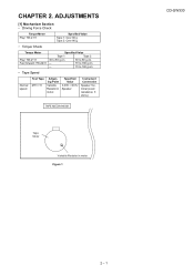
... forward: TW-2231 Specified Value Tape 1 Tape 2 30 to 80 g.cm 30 to 80 g.cm - 70 to 180 g.cm - 70 to 180 g.cm • Tape Speed Normal speed Test Tape MTT-111 Adjusting Point Variable Resistor in motor Figure 1 CD-SW330 2 - 1 CHAPTER 2. Specified Value 3,000 ± 30 Hz Speaker Instrument Connection Speaker Terminal (Load resistance: 6 ohms) TAPE MECHANISM Tape Motor Variable Resistor in motor.
... forward: TW-2231 Specified Value Tape 1 Tape 2 30 to 80 g.cm 30 to 80 g.cm - 70 to 180 g.cm - 70 to 180 g.cm • Tape Speed Normal speed Test Tape MTT-111 Adjusting Point Variable Resistor in motor Figure 1 CD-SW330 2 - 1 CHAPTER 2. Specified Value 3,000 ± 30 Hz Speaker Instrument Connection Speaker Terminal (Load resistance: 6 ohms) TAPE MECHANISM Tape Motor Variable Resistor in motor.

Service Manual
Page 8
... is using manual. Adjustment result automatically will display as below for each 2 sec: a) "FOF_XXXX" b) "TOF_XXXX" c) "TBAL_XX" d) "TGAN_XX" f) "FGAN_XX" g) "RFLS_XX" -------- OFF To cancel : Power OFF 2 - 2 Do normal play. STOP Explanation: a) Focus off set = "FOF_XXXX" b)Tracking off set = "TOF_XXXX" c)Tracking balance = "TBAL_XX" d)Tracking Gain = "TGAN_XX" f) Focus Gain = "FGAN_XX" g) RF level shift = "RFLS_XX" VOL - FLAT X-BASS - Do TOC IL. CD T EST OPEN/CLOSE operation is input into PLAY...
... is using manual. Adjustment result automatically will display as below for each 2 sec: a) "FOF_XXXX" b) "TOF_XXXX" c) "TBAL_XX" d) "TGAN_XX" f) "FGAN_XX" g) "RFLS_XX" -------- OFF To cancel : Power OFF 2 - 2 Do normal play. STOP Explanation: a) Focus off set = "FOF_XXXX" b)Tracking off set = "TOF_XXXX" c)Tracking balance = "TBAL_XX" d)Tracking Gain = "TGAN_XX" f) Focus Gain = "FGAN_XX" g) RF level shift = "RFLS_XX" VOL - FLAT X-BASS - Do TOC IL. CD T EST OPEN/CLOSE operation is input into PLAY...

Service Manual
Page 9
Laser ON. key input. STOP Sliding the PICKUP with>, > button 2 - 3 CD-SW330 Tracking OFF play from that specific point. key input. key input. Tracking ON play at that specific point. Adjustment result automatically will display as below for each 2 sec : a) "FOF_XXXX" b) "TOF_XXXX" c) "TBAL_XX" d) "TGAN_XX" f) "FGAN_XX" g) "RFLS_XX" key input. A key input.
Laser ON. key input. STOP Sliding the PICKUP with>, > button 2 - 3 CD-SW330 Tracking OFF play from that specific point. key input. key input. Tracking ON play at that specific point. Adjustment result automatically will display as below for each 2 sec : a) "FOF_XXXX" b) "TOF_XXXX" c) "TBAL_XX" d) "TGAN_XX" f) "FGAN_XX" g) "RFLS_XX" key input. A key input.

Service Manual
Page 10
...; "FINISHED" appears. 4. Standard Specification of 'ER-CD**'. 'ER-CD**' display will automatically enter to be displayed when error had been detected for transporting. 2 - 4 button, press the GAME/VIDEO button. TUNER PLL Unlock. CD-SW330 [3] CD Section CD Error code description Error 10* 11* 20* 21* 31 Explanation CAM error. When it detect TRAY operation error during initialize process DSP COMMUNICATION ERROR. TRAY error. When it change to enter stand-by mode and Timer indicator will...
...; "FINISHED" appears. 4. Standard Specification of 'ER-CD**'. 'ER-CD**' display will automatically enter to be displayed when error had been detected for transporting. 2 - 4 button, press the GAME/VIDEO button. TUNER PLL Unlock. CD-SW330 [3] CD Section CD Error code description Error 10* 11* 20* 21* 31 Explanation CAM error. When it detect TRAY operation error during initialize process DSP COMMUNICATION ERROR. TRAY error. When it change to enter stand-by mode and Timer indicator will...

Service Manual
Page 55
... sure to change for improvement without any symbol is being played back. 5. CD-SW330 CHAPTER 6. Besides, the one measured by Digital Multimeter between such a section and the chassis with specified ones for maintaining the safety of the set . NO SW701 SW702 SW703 SW704 SW705 SW706 SW707 SW708 DESCRIPTION POWER ON /STAND-BY CD TUNER (BAND) AUX TAPE STOP PLAY FAST FORWARD/PRESET UP...
... sure to change for improvement without any symbol is being played back. 5. CD-SW330 CHAPTER 6. Besides, the one measured by Digital Multimeter between such a section and the chassis with specified ones for maintaining the safety of the set . NO SW701 SW702 SW703 SW704 SW705 SW706 SW707 SW708 DESCRIPTION POWER ON /STAND-BY CD TUNER (BAND) AUX TAPE STOP PLAY FAST FORWARD/PRESET UP...

Service Manual
Page 92
... the objective lens, and check the playback operation. Using the brush in the cleaner cap, apply 1 or 2 drops of the optical pickup is dirty. When the CD does not function The CD section may be effective for about 20 seconds and the CD player will automatically stop button. Turn the power off any adjustment make certain that the lens is accepted, but...
... the objective lens, and check the playback operation. Using the brush in the cleaner cap, apply 1 or 2 drops of the optical pickup is dirty. When the CD does not function The CD section may be effective for about 20 seconds and the CD player will automatically stop button. Turn the power off any adjustment make certain that the lens is accepted, but...

Service Manual
Page 93
...disc is displayed. 1. Does the focus (lens) move ? Yes 4. No Check the laser diode driver Q1 peripheral circuit. No Spindle motor (M1A). No Sled motor (M2A). Although a CD is inserted and the cover is closed, "NO DISC" is loaded, start playback operation. 1. Check the laser diode driver Q1 peripheral circuit. Press the Tray1 CD Eject Button without inserting a disc... 2, 15 and 16 on IC2. Is the turntable rotating ? No If the level is not normal. Does the pickup move up and down ? (Waveform drawing Figure 1) Yes 3. CD-SW330 Yes 2. (1) Focus-RF system check.
...disc is displayed. 1. Does the focus (lens) move ? Yes 4. No Check the laser diode driver Q1 peripheral circuit. No Spindle motor (M1A). No Sled motor (M2A). Although a CD is inserted and the cover is closed, "NO DISC" is loaded, start playback operation. 1. Check the laser diode driver Q1 peripheral circuit. Press the Tray1 CD Eject Button without inserting a disc... 2, 15 and 16 on IC2. Is the turntable rotating ? No If the level is not normal. Does the pickup move up and down ? (Waveform drawing Figure 1) Yes 3. CD-SW330 Yes 2. (1) Focus-RF system check.

Service Manual
Page 96
... 0V. Digital power supply pin. Chip enable signal input pin. H H INPUT Reset input pin for detection problem. Setting in VCO GND pin 3. TES signal generation TE signal input pin. This pin must always be connected to capacitor for monitoring LSI pin. Analog power supply pin. SLED control output pin. D/A converter output. Phase comparison output pin 0 to 0V. Detected sync signal output. Built-in Reset INPUT UNSTABLE UNSTABLE UNSTABLE INPUT INPUT INPUT INPUT UNSTABLE UNSTABLE AVDD/2 UNSTABLE INPUT INPUT UNSTABLE UNSTABLE INPUT UNSTABLE INPUT...
... 0V. Digital power supply pin. Chip enable signal input pin. H H INPUT Reset input pin for detection problem. Setting in VCO GND pin 3. TES signal generation TE signal input pin. This pin must always be connected to capacitor for monitoring LSI pin. Analog power supply pin. SLED control output pin. D/A converter output. Phase comparison output pin 0 to 0V. Detected sync signal output. Built-in Reset INPUT UNSTABLE UNSTABLE UNSTABLE INPUT INPUT INPUT INPUT UNSTABLE UNSTABLE AVDD/2 UNSTABLE INPUT INPUT UNSTABLE UNSTABLE INPUT UNSTABLE INPUT...

Service Manual
Page 97
... and left open. Test input pin 1. Stream data request output pin. Test input pin 0. For use by command from the microprocessor. Digital GND pin. Digital output pin. Output - - Input L - OSCILLATING OSCILLATING - LRVDD/2 - - LRVDD/2 - - Built-in VCO GND pin. Built-in VCO control oscillator range setting input pin. Supply voltage connect to condenser for a 16.9344 MHZ oscillator element. Digital power supply pin. GAMUTEB output pin. LR channel power supply pin. In...
... and left open. Test input pin 1. Stream data request output pin. Test input pin 0. For use by command from the microprocessor. Digital GND pin. Digital output pin. Output - - Input L - OSCILLATING OSCILLATING - LRVDD/2 - - LRVDD/2 - - Built-in VCO GND pin. Built-in VCO control oscillator range setting input pin. Supply voltage connect to condenser for a 16.9344 MHZ oscillator element. Digital power supply pin. GAMUTEB output pin. LR channel power supply pin. In...

Service Manual
Page 101
... for control. IC601 VHiLC75341/-1: Audio Processor (LC75341) Pin No. 1 2 3 4 5 6 7 8 9-12 Terminal Name DI CE VSS LOUT LBASS LTRE LIN LSEL0 L4-1 Function Serial data and clock input pin for control. Chip enable pin. Treble band filter comprising capacitor and resistor connection pin. Volume + equalizer output pin. LSEL0 LIN LTRE LBASS LOUT 87 6 54 L4 9 CD L3 10 Tuner L2 11 Tape L1 12 Video...
... for control. IC601 VHiLC75341/-1: Audio Processor (LC75341) Pin No. 1 2 3 4 5 6 7 8 9-12 Terminal Name DI CE VSS LOUT LBASS LTRE LIN LSEL0 L4-1 Function Serial data and clock input pin for control. Chip enable pin. Treble band filter comprising capacitor and resistor connection pin. Volume + equalizer output pin. LSEL0 LIN LTRE LBASS LOUT 87 6 54 L4 9 CD L3 10 Tuner L2 11 Tape L1 12 Video...

Service Manual
Page 105
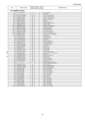
... the set . SHARP CORPORATION This document has been published to change without notice. CD-SW330 PARTS GUIDE MINI COMPONENT SYSTEM MODEL CD-SW330 CD-SW330 Mini Component System consisting of the set . CONTENTS [1] INTEGRATED CIRCUITS [2] TRANSISTORS [3] DIODES [4] TRANSFORMERS [5] COILS [6] VIBRATORS [7] CAPACITORS [8] RESISTORS [9] OTHER CIRCUITRY PARTS [10] CHANGER MECHANISM / CD MECHANISM PARTS [11] CABINET PARTS [12] FRONT SPEAKER BOX PARTS [13] SUBWOOFER [14] ACCESSORIES / PACKING PARTS [15] P.W.B. Be sure to replace these parts with " " are subject to be used...
... the set . SHARP CORPORATION This document has been published to change without notice. CD-SW330 PARTS GUIDE MINI COMPONENT SYSTEM MODEL CD-SW330 CD-SW330 Mini Component System consisting of the set . CONTENTS [1] INTEGRATED CIRCUITS [2] TRANSISTORS [3] DIODES [4] TRANSFORMERS [5] COILS [6] VIBRATORS [7] CAPACITORS [8] RESISTORS [9] OTHER CIRCUITRY PARTS [10] CHANGER MECHANISM / CD MECHANISM PARTS [11] CABINET PARTS [12] FRONT SPEAKER BOX PARTS [13] SUBWOOFER [14] ACCESSORIES / PACKING PARTS [15] P.W.B. Be sure to replace these parts with " " are subject to be used...

Service Manual
Page 118
... Wire Relay Relay Relay Remote Sensor Terminal,Speaker Terminal,Subwoofer Switch,Key Type [Power On/Stand-by] Switch,Key Type [Clock/Timer] Switch,Key Type [Tuning Up] Switch,Key Type [Tuning Down] Switch,Key Type [Fast Rewind/Preset Down] Switch,Key Type [Equalizer] Switch,Key Type [Fast Forward/Preset Up] Switch,Key Type [Tuner (Band)] Switch,Key Type [CD] Switch,Key Type [Tape] Switch,Key Type [Game/Video] Switch,Key Type [X-Bass/Demo] Switch,Key Type [Play] Switch,Key Type [Stop] Switch...
... Wire Relay Relay Relay Remote Sensor Terminal,Speaker Terminal,Subwoofer Switch,Key Type [Power On/Stand-by] Switch,Key Type [Clock/Timer] Switch,Key Type [Tuning Up] Switch,Key Type [Tuning Down] Switch,Key Type [Fast Rewind/Preset Down] Switch,Key Type [Equalizer] Switch,Key Type [Fast Forward/Preset Up] Switch,Key Type [Tuner (Band)] Switch,Key Type [CD] Switch,Key Type [Tape] Switch,Key Type [Game/Video] Switch,Key Type [X-Bass/Demo] Switch,Key Type [Play] Switch,Key Type [Stop] Switch...
Service Manual
Page 123
... BB Tape Mechanism Ass'y AF Panel, Edge Light AC Lug Wire AM Knob, Volume AA Spring, Ring AT Chassis, Main AA Nylon Band AN AC Power Supply Cord AD Bushing, AC Power Supply Cord AD Rotary, Fan AE Bracket, Fan Support A AB Holder, Fuse AZ Heat Sink, Main AD Holder, FL Display AC Bracket, PWB support AB Cushion, Leg ---- NO. PARTS CODE [11] CABINET PARTS 201...
... BB Tape Mechanism Ass'y AF Panel, Edge Light AC Lug Wire AM Knob, Volume AA Spring, Ring AT Chassis, Main AA Nylon Band AN AC Power Supply Cord AD Bushing, AC Power Supply Cord AD Rotary, Fan AE Bracket, Fan Support A AB Holder, Fuse AZ Heat Sink, Main AD Holder, FL Display AC Bracket, PWB support AB Cushion, Leg ---- NO. PARTS CODE [11] CABINET PARTS 201...

Service Manual
Page 127
... AD FM Antenna AM Loop Antenna Remote Control Operation Manual Quick Guide [15] P.W.B. PWB-B 92LPWB6809DPLS - PWB-E 92LPWB6663XMRS - PWB-F QPWBF1055AWZZ AE PWB-G - Main A1 / Power A2 Display B1 / Game Input B2 CD MP3 Front Speaker LED (PWB Only) XM Ready CD Changer Motor (PWB Only) Tape Mechanism (PWB Only) Subwoofer LED [16] OTHER SERVICE PARTS UDSKA0004AFZZ AZ CD Optical Pickup Lens Cleaner Disc CD-SW330 22 PWB-A 92LPWB6809MANS - PWB-D 92LPWB6514LEDS - ASSEMBLY (Not Replacement Item...
... AD FM Antenna AM Loop Antenna Remote Control Operation Manual Quick Guide [15] P.W.B. PWB-B 92LPWB6809DPLS - PWB-E 92LPWB6663XMRS - PWB-F QPWBF1055AWZZ AE PWB-G - Main A1 / Power A2 Display B1 / Game Input B2 CD MP3 Front Speaker LED (PWB Only) XM Ready CD Changer Motor (PWB Only) Tape Mechanism (PWB Only) Subwoofer LED [16] OTHER SERVICE PARTS UDSKA0004AFZZ AZ CD Optical Pickup Lens Cleaner Disc CD-SW330 22 PWB-A 92LPWB6809MANS - PWB-D 92LPWB6514LEDS - ASSEMBLY (Not Replacement Item...


