

Service Manual
Page 3
...path to 0.2 milliamp. Disconnect AC power before returning the audio product to earth ground. CHAPTER 1: GENERAL DESCRIPTION CD-SW330 [1] Important Service Safety Precaution CAUTION : "These servicing instructions are for leakage current in the following safety checks. 1. AC.) Or more is excessive and indicates a potential... shock hazard which must be sure that hardware is not lodged between the chassis and other metal parts in the operating instructions unless you are not pinched or that no modification of any servicing other than that contained in the audio product. 2....
...path to 0.2 milliamp. Disconnect AC power before returning the audio product to earth ground. CHAPTER 1: GENERAL DESCRIPTION CD-SW330 [1] Important Service Safety Precaution CAUTION : "These servicing instructions are for leakage current in the following safety checks. 1. AC.) Or more is excessive and indicates a potential... shock hazard which must be sure that hardware is not lodged between the chassis and other metal parts in the operating instructions unless you are not pinched or that no modification of any servicing other than that contained in the audio product. 2....

Service Manual
Page 74
Refer to "Precautions for handling lead-free solder" for instructions and precautions. CD-SW330 [4] Wiring Side Of PWB MAIN PWB-A1 FROM TAPE 2 RECORD / PLAYBACK HEAD FROM TAPE 1 PLAYBACK HEAD TO DISPLAY PWB-B1 CNP701A FFC701 28 B R149 Q112 ...
Refer to "Precautions for handling lead-free solder" for instructions and precautions. CD-SW330 [4] Wiring Side Of PWB MAIN PWB-A1 FROM TAPE 2 RECORD / PLAYBACK HEAD FROM TAPE 1 PLAYBACK HEAD TO DISPLAY PWB-B1 CNP701A FFC701 28 B R149 Q112 ...
Service Manual
Page 77
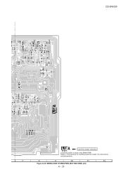
CD-SW330 Q113 R148 R146 Q107 JP107 C120 R122 R124 Q108 R160 C106 R109 R110 R109 R107 C105 R114 R132 R102 C108 R115 R150 R130 C128 C110 ... R830 R831 C951 Lead-free solder indication Lead-free solder is used in the MAIN PWB. Refer to "Precautions for handling lead-free solder" for instructions and precautions. Figure 6-22: WIRING SIDE OF MAIN PWB (BOTTOM VIEW) (2/2) 6 - 23 R934
CD-SW330 Q113 R148 R146 Q107 JP107 C120 R122 R124 Q108 R160 C106 R109 R110 R109 R107 C105 R114 R132 R102 C108 R115 R150 R130 C128 C110 ... R830 R831 C951 Lead-free solder indication Lead-free solder is used in the MAIN PWB. Refer to "Precautions for handling lead-free solder" for instructions and precautions. Figure 6-22: WIRING SIDE OF MAIN PWB (BOTTOM VIEW) (2/2) 6 - 23 R934

Service Manual
Page 78
Refer to "Precautions for handling lead-free solder" for instructions and precautions. Figure 6-23: WIRING SIDE OF POWER PWB (TOP VIEW) 6 - 24 CD-SW330 POWER PWB-A2 BK WH AC POWER SUPPLY CORD AC 120V, 60Hz T.F GR YL GR YL GR RD 8A 125V CNS701 FROM DISPLAY PWB-B1 BI701 COLOR TABLE R D RED W H WHITE B L BLUE B K BLACK Y L YELLOW G R GREEN CNS801 FROM MAIN PWB-A1 Lead-free solder indication Lead-free solder is used in the POWER PWB.
Refer to "Precautions for handling lead-free solder" for instructions and precautions. Figure 6-23: WIRING SIDE OF POWER PWB (TOP VIEW) 6 - 24 CD-SW330 POWER PWB-A2 BK WH AC POWER SUPPLY CORD AC 120V, 60Hz T.F GR YL GR YL GR RD 8A 125V CNS701 FROM DISPLAY PWB-B1 BI701 COLOR TABLE R D RED W H WHITE B L BLUE B K BLACK Y L YELLOW G R GREEN CNS801 FROM MAIN PWB-A1 Lead-free solder indication Lead-free solder is used in the POWER PWB.

Service Manual
Page 80
CD-SW330 DISPLAY PWB-B1 FROM MAIN PWB-A1 CNP701B FFC701 28 1 CNP701A 27 25 23 21 19 17 15 13 11 9 7 5 3 1 28 26 24 22 20 ... RP708 RP706 RD01 Lead-free solder indication Lead-free solder is used in the DISPLAY PWB. Refer to "Precautions for handling lead-free solder" for instructions and precautions. 1 10 12 1 FFC702 FFC705 TO CD MP3 PWB-C CNP6 TO CD MP3 PWB-C CNP3 Figure 6-24: WIRING SIDE OF DISPLAY PWB (TOP VIEW) (1/2) 6 - 26
CD-SW330 DISPLAY PWB-B1 FROM MAIN PWB-A1 CNP701B FFC701 28 1 CNP701A 27 25 23 21 19 17 15 13 11 9 7 5 3 1 28 26 24 22 20 ... RP708 RP706 RD01 Lead-free solder indication Lead-free solder is used in the DISPLAY PWB. Refer to "Precautions for handling lead-free solder" for instructions and precautions. 1 10 12 1 FFC702 FFC705 TO CD MP3 PWB-C CNP6 TO CD MP3 PWB-C CNP3 Figure 6-24: WIRING SIDE OF DISPLAY PWB (TOP VIEW) (1/2) 6 - 26

Service Manual
Page 83
Refer to "Precautions for handling lead-free solder" for instructions and precautions. Figure 6-27: WIRING SIDE DISPLAY PWB (BOTTOM VIEW) (2/2) 6 - 29 CD-SW330 JP706 R738 C729 C727 RP742 RP754 RP753 RP768 RP752 RP790 RP777 C716 C717 RP789 IC702 R770 R772 R773 R774 R775 R776 R778 R777 R779 R780 ...
Refer to "Precautions for handling lead-free solder" for instructions and precautions. Figure 6-27: WIRING SIDE DISPLAY PWB (BOTTOM VIEW) (2/2) 6 - 29 CD-SW330 JP706 R738 C729 C727 RP742 RP754 RP753 RP768 RP752 RP790 RP777 C716 C717 RP789 IC702 R770 R772 R773 R774 R775 R776 R778 R777 R779 R780 ...

Service Manual
Page 84
CD-SW330 GAME INPUT PWB-B2 FW901 1 BI801 TO MAIN PWB-A1 5 1 23 4 5 FROM MAIN PWB-A1 CNP 603 JK692 HEADPHONES WTM901 5 4 3 21 JK690 VIDEO IN L690 R-CH AUX/VIDEO L-CH R693 R691 C694 R690 BI603 1 23 4 56 WH GY WH BK BK WH WH BK GY BK PK PK C692 C697 R692 LUG 3 Lead-free solder indication Lead-free solder is used in the GAME INPUT PWB. Refer to "Precautions for handling lead-free solder" for instructions and precautions. LUG TERMINAL COLOR TABLE GY GRAY W H WHITE B K BLACK P K PINK Figure 6-28: WIRING SIDE OF GAME INPUT PWB (TOP VIEW) 6 - 30
CD-SW330 GAME INPUT PWB-B2 FW901 1 BI801 TO MAIN PWB-A1 5 1 23 4 5 FROM MAIN PWB-A1 CNP 603 JK692 HEADPHONES WTM901 5 4 3 21 JK690 VIDEO IN L690 R-CH AUX/VIDEO L-CH R693 R691 C694 R690 BI603 1 23 4 56 WH GY WH BK BK WH WH BK GY BK PK PK C692 C697 R692 LUG 3 Lead-free solder indication Lead-free solder is used in the GAME INPUT PWB. Refer to "Precautions for handling lead-free solder" for instructions and precautions. LUG TERMINAL COLOR TABLE GY GRAY W H WHITE B K BLACK P K PINK Figure 6-28: WIRING SIDE OF GAME INPUT PWB (TOP VIEW) 6 - 30

Service Manual
Page 85
Figure 6-29: WIRING SIDE OF GAME INPUT PWB (BOTTOM VIEW) 6 - 31 GAME INPUT PWB-B2 CD-SW330 C755 C754 Lead-free solder indication Lead-free solder is used in the GAME INPUT PWB. Refer to "Precautions for handling lead-free solder" for instructions and precautions.
Figure 6-29: WIRING SIDE OF GAME INPUT PWB (BOTTOM VIEW) 6 - 31 GAME INPUT PWB-B2 CD-SW330 C755 C754 Lead-free solder indication Lead-free solder is used in the GAME INPUT PWB. Refer to "Precautions for handling lead-free solder" for instructions and precautions.

Service Manual
Page 87
Refer to "Precautions for handling lead-free solder" for instructions and precautions. 7 8 9 10 11 12 Figure 6-31: WIRING SIDE OF CD MP3 PWB (TOP VIEW) (2/2) 6 - 33 BL R26 FROM PLAY PWB-B1 CNP705 FROM MAIN PWB-A1 BI601 FROM DISPLAY PWB-B1 CNP702 RD BL GR ... 9 8765432 1 75 3 1 WIRE_B' CNP6 2 4 6 8 10 1 3 57 9 WH C67 C69 R36 R33 R32 R31 R30 R29 R28 R27 C75 C76 C40 57 C42 WH R35 WIRE_B CD-SW330 X1 C60 C15 R12 R13 C2 C22 2 4 6 8 10 12 14 16 L5 1 3 5 7 9 11 13 15 C4 CNP1 1 16 FFC1 TO...
Refer to "Precautions for handling lead-free solder" for instructions and precautions. 7 8 9 10 11 12 Figure 6-31: WIRING SIDE OF CD MP3 PWB (TOP VIEW) (2/2) 6 - 33 BL R26 FROM PLAY PWB-B1 CNP705 FROM MAIN PWB-A1 BI601 FROM DISPLAY PWB-B1 CNP702 RD BL GR ... 9 8765432 1 75 3 1 WIRE_B' CNP6 2 4 6 8 10 1 3 57 9 WH C67 C69 R36 R33 R32 R31 R30 R29 R28 R27 C75 C76 C40 57 C42 WH R35 WIRE_B CD-SW330 X1 C60 C15 R12 R13 C2 C22 2 4 6 8 10 12 14 16 L5 1 3 5 7 9 11 13 15 C4 CNP1 1 16 FFC1 TO...

Service Manual
Page 88
CD-SW330 CD MP3 PWB-C A B C71 R55 C51 C49 C48 C50 C C53 R38 R37 R1 C6 C52 R34 C54 D C55 R2 R3 R5 R4 C10 C8 C7 C11 E C12 C16 C14 R7 C13 1 C17 C18 C21 C25 C20 C19 C23 R9 R10 R8 F R11 Q1 RA16 RA15 R6 C5 G Lead-free solder indication Lead-free solder is used in the CD MP3 PWB. H Refer to "Precautions for handling lead-free solder" for instructions and precautions. 1 2 3 4 5 6 Figure 6-32 WIRING SIDE OF CD MP3 PWB (BOTTOM VIEW) (1/2) 6 - 34
CD-SW330 CD MP3 PWB-C A B C71 R55 C51 C49 C48 C50 C C53 R38 R37 R1 C6 C52 R34 C54 D C55 R2 R3 R5 R4 C10 C8 C7 C11 E C12 C16 C14 R7 C13 1 C17 C18 C21 C25 C20 C19 C23 R9 R10 R8 F R11 Q1 RA16 RA15 R6 C5 G Lead-free solder indication Lead-free solder is used in the CD MP3 PWB. H Refer to "Precautions for handling lead-free solder" for instructions and precautions. 1 2 3 4 5 6 Figure 6-32 WIRING SIDE OF CD MP3 PWB (BOTTOM VIEW) (1/2) 6 - 34

Service Manual
Page 90
Figure 6-34: WIRING SIDE OF XM READY PWB (TOP VIEW) 6 - 36 CD-SW330 XM READY PWB-E FROM MAIN PWB-A1 CNP702B FFC702 1 18 TPM509 TPM504 TPM505 TPM510 1 TPM502 RD547 C546 RD545 R544 R543 R541 RC505 CC505 TPA516 TPM506 ... READY PASSPORT Lead-free solder indication Lead-free solder is used in the XM READY PWB. Refer to "Precautions for handling lead-free solder" for instructions and precautions.
Figure 6-34: WIRING SIDE OF XM READY PWB (TOP VIEW) 6 - 36 CD-SW330 XM READY PWB-E FROM MAIN PWB-A1 CNP702B FFC702 1 18 TPM509 TPM504 TPM505 TPM510 1 TPM502 RD547 C546 RD545 R544 R543 R541 RC505 CC505 TPA516 TPM506 ... READY PASSPORT Lead-free solder indication Lead-free solder is used in the XM READY PWB. Refer to "Precautions for handling lead-free solder" for instructions and precautions.

Service Manual
Page 91
... CNP102 TO MAIN PWB-A1 Figure 6-35: WIRING SIDE OF TAPE MECHANISM PWB (TOP VIEW) 6 - 37 Refer to "Precautions for handling lead-free solder" for instructions and precautions. CD-SW330 TAPE MECHANISM ASSEMBLY TO DISPLAY PWB-B1 CNP704 FFC704 1 7 1 357 246 SW 1 2 SOLENOID Lead-free solder is used in this PWB.
... CNP102 TO MAIN PWB-A1 Figure 6-35: WIRING SIDE OF TAPE MECHANISM PWB (TOP VIEW) 6 - 37 Refer to "Precautions for handling lead-free solder" for instructions and precautions. CD-SW330 TAPE MECHANISM ASSEMBLY TO DISPLAY PWB-B1 CNP704 FFC704 1 7 1 357 246 SW 1 2 SOLENOID Lead-free solder is used in this PWB.

Service Manual
Page 92
... key is taken, check the following items. Remove the cabinet and follow the troubleshooting instructions. Cleaning fluid CAUTION The CD lens cleaner should be used on car CD players or on the laser pickup lens. Unauthorized duplicating, broadcasting and renting this happening then drink ...the cleaner fluid or allow it . 2. Cleaner disc 2. When a CD cannot be caused by law. Before attempting any excess fluid with the brush side down,then press the play continuously, press the stop . CD-SW330 CHAPTER 7. FLOWCHART [1] Troubleshooting 1. Do not touch the lens with the...
... key is taken, check the following items. Remove the cabinet and follow the troubleshooting instructions. Cleaning fluid CAUTION The CD lens cleaner should be used on car CD players or on the laser pickup lens. Unauthorized duplicating, broadcasting and renting this happening then drink ...the cleaner fluid or allow it . 2. Cleaner disc 2. When a CD cannot be caused by law. Before attempting any excess fluid with the brush side down,then press the play continuously, press the stop . CD-SW330 CHAPTER 7. FLOWCHART [1] Troubleshooting 1. Do not touch the lens with the...