

Service Manual
Page 2
... maximum heat-resistance temperature of the soldering bit, it is blackened during use, file it . i - CD-SW330 AXSMEPeuLRard-MvrEMkiiocePCPet1A1M550U0aTnuIOalNS FOR USING LEAD-FREE SOLDER 1. Employing lead-free solder "MAIN, POWER, DISPLAY, GAME INPUT, CD MP3, FRONT SPEAKER LED, XM READY, CD CHANGER MOTOR (PWB ONLY), SUB WOOFER LED " of tin,silver and copper. 2. Example: Indicates...
... maximum heat-resistance temperature of the soldering bit, it is blackened during use, file it . i - CD-SW330 AXSMEPeuLRard-MvrEMkiiocePCPet1A1M550U0aTnuIOalNS FOR USING LEAD-FREE SOLDER 1. Employing lead-free solder "MAIN, POWER, DISPLAY, GAME INPUT, CD MP3, FRONT SPEAKER LED, XM READY, CD CHANGER MOTOR (PWB ONLY), SUB WOOFER LED " of tin,silver and copper. 2. Example: Indicates...

Service Manual
Page 3
...ground connected to earth ground. WARNING 1. To reduce the risk of 0.3 volt RMS (this corresponds to 0.2 milliamp. CHAPTER 1: GENERAL DESCRIPTION CD-SW330 [1] Important Service Safety Precaution CAUTION : "These servicing instructions are for U.S.A only) BEFORE RETURNING THE AUDIO PRODUCT (Fire & Shock Hazard) ...insulating materials, cabinet, terminal board, adjustment and compartment covers or shields, mechanical insulators etc. Disconnect AC power before returning the audio product to measure the AC voltage drop across the resistor. Any reading of electric shock do so".
...ground connected to earth ground. WARNING 1. To reduce the risk of 0.3 volt RMS (this corresponds to 0.2 milliamp. CHAPTER 1: GENERAL DESCRIPTION CD-SW330 [1] Important Service Safety Precaution CAUTION : "These servicing instructions are for U.S.A only) BEFORE RETURNING THE AUDIO PRODUCT (Fire & Shock Hazard) ...insulating materials, cabinet, terminal board, adjustment and compartment covers or shields, mechanical insulators etc. Disconnect AC power before returning the audio product to measure the AC voltage drop across the resistor. Any reading of electric shock do so".

Service Manual
Page 4
... of our policy of continuous improvement, SHARP reserves the right to 20 KHz, 10% total harmonic distortion. CD-SW330 General Power source AC 120 V, 60 Hz Power consumption 195 W Dimensions Width: 10-1/4" (260 mm) Height: 13" (330 mm) Depth: 12-7/8" (323 mm) Weight 22 lbs. (10 kg) Amplifier Output power Output terminals Input terminals Front Speakers...
... of our policy of continuous improvement, SHARP reserves the right to 20 KHz, 10% total harmonic distortion. CD-SW330 General Power source AC 120 V, 60 Hz Power consumption 195 W Dimensions Width: 10-1/4" (260 mm) Height: 13" (330 mm) Depth: 12-7/8" (323 mm) Weight 22 lbs. (10 kg) Amplifier Output power Output terminals Input terminals Front Speakers...
Service Manual
Page 5
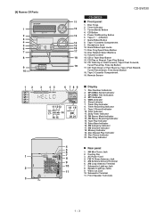
...CD Play or Repeat, Tape Play Button 16. MP3/WMA Folder Indicator 3. MP3/WMA Title Indicators 4. Timer Recording Indicator 9. Tape 2 Record Indicator 10. Disc Repeat Play Indicator 20. Disc Pause Indicator 21. AC Power Cord 4. AM Antenna Ground Terminal 6. Subwoofer Light-up Jacks 11 9. Speaker Light-up Jack 2 8. Disc Trays 2. Power...Timer Indicator 12. FM Stereo Mode Indicator 13. Tape Play Indicator 15. [4] Names Of Parts CD-SW330 CD-SW330 Front panel 1. Disc Number Select Buttons 13. Disc Number Indicators 2. Subwoofer Terminal 11. Game/Video Input Jacks...
...CD Play or Repeat, Tape Play Button 16. MP3/WMA Folder Indicator 3. MP3/WMA Title Indicators 4. Timer Recording Indicator 9. Tape 2 Record Indicator 10. Disc Repeat Play Indicator 20. Disc Pause Indicator 21. AC Power Cord 4. AM Antenna Ground Terminal 6. Subwoofer Light-up Jacks 11 9. Speaker Light-up Jack 2 8. Disc Trays 2. Power...Timer Indicator 12. FM Stereo Mode Indicator 13. Tape Play Indicator 15. [4] Names Of Parts CD-SW330 CD-SW330 Front panel 1. Disc Number Select Buttons 13. Disc Number Indicators 2. Subwoofer Terminal 11. Game/Video Input Jacks...

Service Manual
Page 6
... Up or Fast Forward, Tape Fast Forward, Tuner Preset Up, Time Up, Cursor Right Button 24. Folder Button 28. Speaker Light-Up Wire CP-SW330 Subwoofer 1. Subwoofer Light-Up Wire 4. CD-SW330 1 2 3 4 5 6 7 1 2 3 1 2 13 17 8 9 14 18 10 15 19 20 11 16 21 12 22 23 24 25 ... 7. CD Button 10. Tape 2 Record Pause Button 22. XM Menu Button 29. XM Display Button CP-S330 Front Speaker 1. Bass Reflex Duct 5. Speaker Wire 3 4 1 - 43 Tuner (Band)/XM Button 11. Memory Button 18. Tuning Down, Cursor Down Button 26. XM Enter Button 30. Speaker Wire 6. Power On/...
... Up or Fast Forward, Tape Fast Forward, Tuner Preset Up, Time Up, Cursor Right Button 24. Folder Button 28. Speaker Light-Up Wire CP-SW330 Subwoofer 1. Subwoofer Light-Up Wire 4. CD-SW330 1 2 3 4 5 6 7 1 2 3 1 2 13 17 8 9 14 18 10 15 19 20 11 16 21 12 22 23 24 25 ... 7. CD Button 10. Tape 2 Record Pause Button 22. XM Menu Button 29. XM Display Button CP-S330 Front Speaker 1. Bass Reflex Duct 5. Speaker Wire 3 4 1 - 43 Tuner (Band)/XM Button 11. Memory Button 18. Tuning Down, Cursor Down Button 26. XM Enter Button 30. Speaker Wire 6. Power On/...

Service Manual
Page 8
CD-SW330 [2] Test Mode • Setting the test mode During stand-by mode, press GAME/VIDEO button while pressing down the button and button. IL isn't done IL isn't done >,>buttons make pick's slide possible. Last memory P.GEQ - OFF To cancel : Power OFF 2 - 2 key input. > key: Track 4 > key: Track 9 > key: Track 15 key input...
CD-SW330 [2] Test Mode • Setting the test mode During stand-by mode, press GAME/VIDEO button while pressing down the button and button. IL isn't done IL isn't done >,>buttons make pick's slide possible. Last memory P.GEQ - OFF To cancel : Power OFF 2 - 2 key input. > key: Track 4 > key: Track 9 > key: Track 15 key input...

Service Manual
Page 9
key input. Adjustment result automatically will display as below for each 2 sec : a) "FOF_XXXX" b) "TOF_XXXX" c) "TBAL_XX" d) "TGAN_XX" f) "FGAN_XX" g) "RFLS_XX" key input. key input. Tracking ON play at that specific point. A key input. STOP Sliding the PICKUP with>, > button 2 - 3 CD-SW330 Laser ON. Tracking OFF play from that specific point. key input.
key input. Adjustment result automatically will display as below for each 2 sec : a) "FOF_XXXX" b) "TOF_XXXX" c) "TBAL_XX" d) "TGAN_XX" f) "FGAN_XX" g) "RFLS_XX" key input. key input. Tracking ON play at that specific point. A key input. STOP Sliding the PICKUP with>, > button 2 - 3 CD-SW330 Laser ON. Tracking OFF play from that specific point. key input.

Service Manual
Page 10
...as below. Press button until "WAIT"→ "FINISHED" appears. 4. CD DSP Communication Error. by mode. 2. Unplug the AC cord and the unit is condition when irregular process occur on power supply line. BEFORE TRANSPORTING THE UNIT The following process need to enter ...3. Speaker abnormal detection and +B PROTECTION display In case speaker abnormal detection or +B PROTECTION had been detected for the 5th times. CD-SW330 [3] CD Section CD Error code description Error 10* 11* 20* 21* 31 Explanation CAM error. When it detect cam operation error during initialize process...
...as below. Press button until "WAIT"→ "FINISHED" appears. 4. CD DSP Communication Error. by mode. 2. Unplug the AC cord and the unit is condition when irregular process occur on power supply line. BEFORE TRANSPORTING THE UNIT The following process need to enter ...3. Speaker abnormal detection and +B PROTECTION display In case speaker abnormal detection or +B PROTECTION had been detected for the 5th times. CD-SW330 [3] CD Section CD Error code description Error 10* 11* 20* 21* 31 Explanation CAM error. When it detect cam operation error during initialize process...
Service Manual
Page 43
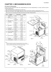
...) x1 3 1. Screw G1) x4 3 1. Screw L4) x6 1. Screw P1) x4 8 2. Screw Q1) x4 9 CD Servo PWB CD Changer Unit (C3)x1 (C2)x1 PULL Hook (C1)x1 (E3)x1 Power PWB Front Panel (E2)x1 Hook (C1)x1 PULL Rear Panel (D1)x11 O 3x10mm Fan Motor Figure 2 Lug...J1) x6 5 2. Screw B1) x8 1 1. Hook C1) x2 2 2. Flat Cable J2) x1 1. Nut L2) x1 3. MECHANISM BLOCKS CSMEeDarrv-kEiceSet7M00a/nCuDal-ES77 CD-SW330 [1] Caution On Disassembly Follow the below-mentioned notes when disassembling the unit and reassembling it, to protect the optical pickup from the wall outlet before...
...) x1 3 1. Screw G1) x4 3 1. Screw L4) x6 1. Screw P1) x4 8 2. Screw Q1) x4 9 CD Servo PWB CD Changer Unit (C3)x1 (C2)x1 PULL Hook (C1)x1 (E3)x1 Power PWB Front Panel (E2)x1 Hook (C1)x1 PULL Rear Panel (D1)x11 O 3x10mm Fan Motor Figure 2 Lug...J1) x6 5 2. Screw B1) x8 1 1. Hook C1) x2 2 2. Flat Cable J2) x1 1. Nut L2) x1 3. MECHANISM BLOCKS CSMEeDarrv-kEiceSet7M00a/nCuDal-ES77 CD-SW330 [1] Caution On Disassembly Follow the below-mentioned notes when disassembling the unit and reassembling it, to protect the optical pickup from the wall outlet before...

Service Manual
Page 55
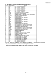
...HSS4148 FRONT VIEW 1 2 3 KIA7805 KDS184 KDS226 AC AC TS20P05G D10XB60F SLR342VC SDPB40F2A 343BD2S 503BC2E 6 - 1 CD-SW330 CHAPTER 6. In the tuner section, indicates AM indicates FM stereo 2. In the CD section, the CD is stopped. • Parts marked with " " ( ) are subject to electrolytic capacitor, the expression "...symbol is being played back. ( ) indicates the record state. 4. In the power section, a tape is microfarad. NO SW701 SW702 SW703 SW704 SW705 SW706 SW707 SW708 DESCRIPTION POWER ON /STAND-BY CD TUNER (BAND) AUX TAPE STOP PLAY FAST FORWARD/PRESET UP POSITION ON-OFF ...
...HSS4148 FRONT VIEW 1 2 3 KIA7805 KDS184 KDS226 AC AC TS20P05G D10XB60F SLR342VC SDPB40F2A 343BD2S 503BC2E 6 - 1 CD-SW330 CHAPTER 6. In the tuner section, indicates AM indicates FM stereo 2. In the CD section, the CD is stopped. • Parts marked with " " ( ) are subject to electrolytic capacitor, the expression "...symbol is being played back. ( ) indicates the record state. 4. In the power section, a tape is microfarad. NO SW701 SW702 SW703 SW704 SW705 SW706 SW707 SW708 DESCRIPTION POWER ON /STAND-BY CD TUNER (BAND) AUX TAPE STOP PLAY FAST FORWARD/PRESET UP POSITION ON-OFF ...

Service Manual
Page 56
TO POWER IC SECTION FROM POWER SECTION TO CD MP3 TO TUNER PACK CD-SW330 [3] Schematic Diagram Figure 6-1: MAIN SCHEMATIC DIAGRAM (1/2) 6 - 2
TO POWER IC SECTION FROM POWER SECTION TO CD MP3 TO TUNER PACK CD-SW330 [3] Schematic Diagram Figure 6-1: MAIN SCHEMATIC DIAGRAM (1/2) 6 - 2

Service Manual
Page 74
CD-SW330 [4] Wiring Side Of PWB MAIN PWB-A1 FROM TAPE 2 RECORD / PLAYBACK HEAD FROM TAPE 1 PLAYBACK HEAD TO DISPLAY PWB-B1 CNP701A FFC701 28 B R149 Q112 ... I 1 ZD901 C9 D819 R835 C938 R948 R947 R949 C913 R837 R946 D817 1 2 3 4 5 6 7 8 9 10 11 R836 R934 D818 FROM GAME INPUT PWB-A2 WTM901 FW901 TO POWER PWB-A2 CNP801 1 2 3 4 5 6 7 8 9 10 C848 C849 CNP901 1 2 3 45 Lead-free solder indication LG1 Lead-free solder is used in the MAIN PWB. Figure 6-19: WIRING...
CD-SW330 [4] Wiring Side Of PWB MAIN PWB-A1 FROM TAPE 2 RECORD / PLAYBACK HEAD FROM TAPE 1 PLAYBACK HEAD TO DISPLAY PWB-B1 CNP701A FFC701 28 B R149 Q112 ... I 1 ZD901 C9 D819 R835 C938 R948 R947 R949 C913 R837 R946 D817 1 2 3 4 5 6 7 8 9 10 11 R836 R934 D818 FROM GAME INPUT PWB-A2 WTM901 FW901 TO POWER PWB-A2 CNP801 1 2 3 4 5 6 7 8 9 10 C848 C849 CNP901 1 2 3 45 Lead-free solder indication LG1 Lead-free solder is used in the MAIN PWB. Figure 6-19: WIRING...

Service Manual
Page 78
Refer to "Precautions for handling lead-free solder" for instructions and precautions. Figure 6-23: WIRING SIDE OF POWER PWB (TOP VIEW) 6 - 24 CD-SW330 POWER PWB-A2 BK WH AC POWER SUPPLY CORD AC 120V, 60Hz T.F GR YL GR YL GR RD 8A 125V CNS701 FROM DISPLAY PWB-B1 BI701 COLOR TABLE R D RED W H WHITE B L BLUE B K BLACK Y L YELLOW G R GREEN CNS801 FROM MAIN PWB-A1 Lead-free solder indication Lead-free solder is used in the POWER PWB.
Refer to "Precautions for handling lead-free solder" for instructions and precautions. Figure 6-23: WIRING SIDE OF POWER PWB (TOP VIEW) 6 - 24 CD-SW330 POWER PWB-A2 BK WH AC POWER SUPPLY CORD AC 120V, 60Hz T.F GR YL GR YL GR RD 8A 125V CNS701 FROM DISPLAY PWB-B1 BI701 COLOR TABLE R D RED W H WHITE B L BLUE B K BLACK Y L YELLOW G R GREEN CNS801 FROM MAIN PWB-A1 Lead-free solder indication Lead-free solder is used in the POWER PWB.

Service Manual
Page 92
...play continuously, press the stop . Turn the power off any adjustment make certain that the lens is prohibited by build up of isopropyl alcohol. Do not drink the cleaner fluid or allow it still play button. 3. If the CD cleaner brushes become worn out earlier then please... for 30-50 operations, however if the brushes become very wet then wipe off . CD optical pickup Lens cleaner disc Parts code UDSKA0004AFZZ HOW TO USE 1. Pressing the CD operation key is dirty. CD-SW330 CHAPTER 7. When this product is clean. You will automatically stop button. Clean the objective...
...play continuously, press the stop . Turn the power off any adjustment make certain that the lens is prohibited by build up of isopropyl alcohol. Do not drink the cleaner fluid or allow it still play button. 3. If the CD cleaner brushes become worn out earlier then please... for 30-50 operations, however if the brushes become very wet then wipe off . CD optical pickup Lens cleaner disc Parts code UDSKA0004AFZZ HOW TO USE 1. Pressing the CD operation key is dirty. CD-SW330 CHAPTER 7. When this product is clean. You will automatically stop button. Clean the objective...

Service Manual
Page 96
... connection pin. D/A converter output. Input Input Input Output L INPUT L L L - - INPUT INPUT INPUT H DMUTEB output pin. Built-in VCO power supply pin 3. Micro- Chip enable signal input pin. In this unit, the terminal with asterisk mark (*) is (open . LPF capacitor pin for monitoring...Input Input Output Output Output Output Input Input Output Output Input Output Input - - Phase comparison output pin 0 to 0V. CD-SW330 CHAPTER 8. TE signal output pin. by command from the EFM signal and the internally generated sync signal agree. Digital GND...
... connection pin. D/A converter output. Input Input Input Output L INPUT L L L - - INPUT INPUT INPUT H DMUTEB output pin. Built-in VCO power supply pin 3. Micro- Chip enable signal input pin. In this unit, the terminal with asterisk mark (*) is (open . LPF capacitor pin for monitoring...Input Input Output Output Output Output Input Input Output Output Input Output Input - - Phase comparison output pin 0 to 0V. CD-SW330 CHAPTER 8. TE signal output pin. by command from the EFM signal and the internally generated sync signal agree. Digital GND...

Service Manual
Page 97
...clock output pin. Built-in Reset INPUT INPUT L INPUT INPUT INPUT L L L L - Supply voltage connect to the outside. 8 - 2 Digital output pin. Digital power supply pin. Analog power supply pin. Output Output - Output - - Setting in VCO control voltage setting input pin. Input L - Function General Purpose I/O pin 1 General Purpose I/O pin 0 ...Output Input/Output Input/Output Input Output Output Output - Output - - This pin must always be connected to 0V. IC1 VHiLC78690E-1: CD Servo (LC78690E) (2/2) CD-SW330 Pin No. Output - - Built-in VCO power supply pin 2.
...clock output pin. Built-in Reset INPUT INPUT L INPUT INPUT INPUT L L L L - Supply voltage connect to the outside. 8 - 2 Digital output pin. Digital power supply pin. Analog power supply pin. Output Output - Output - - Setting in VCO control voltage setting input pin. Input L - Function General Purpose I/O pin 1 General Purpose I/O pin 0 ...Output Input/Output Input/Output Input Output Output Output - Output - - This pin must always be connected to 0V. IC1 VHiLC78690E-1: CD Servo (LC78690E) (2/2) CD-SW330 Pin No. Output - - Built-in VCO power supply pin 2.
Service Manual
Page 99
CD-SW330 IC2 VHILA6261//-1: Focus/Tracking/Spin/Sled Driver (LA6261) Pin No. Logic input for bridge. 21 VCONT5 Input pin for bridge. 20 REV5 CH5 Output change ... channel 3. 3 VO2+ BTL Output pin (+) for CH5 output voltage control. 25 VREFIN Reference voltage input pin. 26 SGND Signal system GND 27 SVCC Signal system power (PVCC1 short - BTL Output pin (-) for channel 2. 5 VO1+ BTL Output pin (+) for channel 6. 32 VO6- Logic input for CH5 output voltage control 22 FWD6 CH6...
CD-SW330 IC2 VHILA6261//-1: Focus/Tracking/Spin/Sled Driver (LA6261) Pin No. Logic input for bridge. 21 VCONT5 Input pin for bridge. 20 REV5 CH5 Output change ... channel 3. 3 VO2+ BTL Output pin (+) for CH5 output voltage control. 25 VREFIN Reference voltage input pin. 26 SGND Signal system GND 27 SVCC Signal system power (PVCC1 short - BTL Output pin (-) for channel 2. 5 VO1+ BTL Output pin (+) for channel 6. 32 VO6- Logic input for CH5 output voltage control 22 FWD6 CH6...

Service Manual
Page 101
.... 0.5x VDD voltage generation block for control. Capacitor of "H" to be connected between VREF and AWSS (VSS) as a countermeasure against power ripple. LSEL0 LIN LTRE LBASS LOUT 87 6 54 L4 9 CD L3 10 Tuner L2 11 Tape L1 12 Video R1 13 R2 14 R3 15 R4 16 CONTROL CIRCUIT CONTROL CIRCUIT... and bass/treble output pin. Bass band filter comprising capacitor and resistor connection pin. Supply pin Serial data and clock input pin for analog ground. CD-SW330 Pin No. 13-16 17 18 19 20 21 22 23 24 Terminal Name R1-4 RSEL0 RIN RTRE RBASS ROUT VREF VDD CLK Function Input...
.... 0.5x VDD voltage generation block for control. Capacitor of "H" to be connected between VREF and AWSS (VSS) as a countermeasure against power ripple. LSEL0 LIN LTRE LBASS LOUT 87 6 54 L4 9 CD L3 10 Tuner L2 11 Tape L1 12 Video R1 13 R2 14 R3 15 R4 16 CONTROL CIRCUIT CONTROL CIRCUIT... and bass/treble output pin. Bass band filter comprising capacitor and resistor connection pin. Supply pin Serial data and clock input pin for analog ground. CD-SW330 Pin No. 13-16 17 18 19 20 21 22 23 24 Terminal Name R1-4 RSEL0 RIN RTRE RBASS ROUT VREF VDD CLK Function Input...

Service Manual
Page 102
... Protection, Thermal Protection, Load Short Protection. Prc Drive + - CD-SW330 IC851 VHIAN80T53/-1: Multi Regulator (AN80T53) Pin Terminal Name Function No. 1 REG4 Output 5.1 V power supply with a minimum peak out current of 1200 mA. 2 REG3 Output 13 V power supply with a minimum peak out current of 1350 mA. 3... VCC Connected to Power supplies. 4 GND Connected to the IC substrate. 5 MODE...
... Protection, Thermal Protection, Load Short Protection. Prc Drive + - CD-SW330 IC851 VHIAN80T53/-1: Multi Regulator (AN80T53) Pin Terminal Name Function No. 1 REG4 Output 5.1 V power supply with a minimum peak out current of 1200 mA. 2 REG3 Output 13 V power supply with a minimum peak out current of 1350 mA. 3... VCC Connected to Power supplies. 4 GND Connected to the IC substrate. 5 MODE...

Service Manual
Page 107
...,12V,DZ12 AB Zener,12V,DZ12 AB Zener,11V,DZ11 AB Zener,30V,DZ30 BP Power (Main) AL Power (Sub) AB Ferrite Beads,BLM18AG121SN1D AB Ferrite Beads,BLM18AG121SN1D Ferrite Bead AB 330 μ H,Choke 2.2µ H,Peaking 2.2µ H,Peaking 2 CD-SW330 PARTS CODE [2] TRANSISTORS Q910 Q914 Q915 Q916 QX503 QX504 VSKTC3203Y/-1 VSKTC3875GR-1 VSKTA1504GR-1 VSKRC104S//-1 VSKRC107S...
...,12V,DZ12 AB Zener,12V,DZ12 AB Zener,11V,DZ11 AB Zener,30V,DZ30 BP Power (Main) AL Power (Sub) AB Ferrite Beads,BLM18AG121SN1D AB Ferrite Beads,BLM18AG121SN1D Ferrite Bead AB 330 μ H,Choke 2.2µ H,Peaking 2.2µ H,Peaking 2 CD-SW330 PARTS CODE [2] TRANSISTORS Q910 Q914 Q915 Q916 QX503 QX504 VSKTC3203Y/-1 VSKTC3875GR-1 VSKTA1504GR-1 VSKRC104S//-1 VSKRC107S...


