Service Manual
Page 4
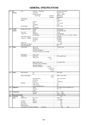
...~ +60oC Less than 25.5 inch / 647.7mmV Color TFT LCD 1366(H) x 768(V) 88/88 degree 88/88 degree NTSC 2 Speaker Front 1.6 x 4.8 inch 4 ohm 5.0W + 5.0W --- GENERAL SPECIFICATIONS G-1 TV System G-2 Tuning System G-3 Signal LCD Color System Speaker Sound Output Broadcasting System Tuner and Receive CH Intermediate ...Digital Frequency Analog Preset CH Stereo/Dual TV Sound Tuner Sound Muting Video Signal LCD Size / Visual Size LCD Type Number of Pixels View Range Position Size Impedance Max 10%(Typical) Analog Digital System Destination CH Coverage...
...~ +60oC Less than 25.5 inch / 647.7mmV Color TFT LCD 1366(H) x 768(V) 88/88 degree 88/88 degree NTSC 2 Speaker Front 1.6 x 4.8 inch 4 ohm 5.0W + 5.0W --- GENERAL SPECIFICATIONS G-1 TV System G-2 Tuning System G-3 Signal LCD Color System Speaker Sound Output Broadcasting System Tuner and Receive CH Intermediate ...Digital Frequency Analog Preset CH Stereo/Dual TV Sound Tuner Sound Muting Video Signal LCD Size / Visual Size LCD Type Number of Pixels View Range Position Size Impedance Max 10%(Typical) Analog Digital System Destination CH Coverage...
Service Manual
Page 22
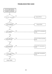
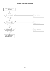
...IC1002 and peripheral circuit. No Is there signal at pins 2 Yes and 5 of CP1001? No Yes Is there signal at pins Yes 1 and 4 of IC1001? Check IC901 and peripheral circuit. No Change TU2801. Check IC701 and peripheral circuit. Yes Is there signal at pin 15 of IC1002? E-2 TROUBLESHOOTING... GUIDE THE PICTURE APPEARS, BUT THE AUDIO DOES NOT APPEARS. (ATRFMODE) No Is CP1001 connected? No Is there signal at pins 1 Yes and 20 of TU2801? Change SP1001. Check...
...IC1002 and peripheral circuit. No Is there signal at pins 2 Yes and 5 of CP1001? No Yes Is there signal at pins Yes 1 and 4 of IC1001? Check IC901 and peripheral circuit. No Change TU2801. Check IC701 and peripheral circuit. Yes Is there signal at pin 15 of IC1002? E-2 TROUBLESHOOTING... GUIDE THE PICTURE APPEARS, BUT THE AUDIO DOES NOT APPEARS. (ATRFMODE) No Is CP1001 connected? No Is there signal at pins 1 Yes and 20 of TU2801? Change SP1001. Check...
Service Manual
Page 23
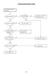
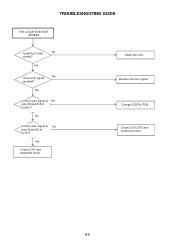
Yes Check DIGITAL PCB. Yes Is there signal at IC2405? Check Q3410 and peripheral circuit. Change V2301(PANEL). Yes No Is CD7201 connected? Change IC2405. No No Is there signal at pins 7, Yes 8, 10, 11, 13, 14, 16, 17, 19 and 20 of CD7201? Yes Is there voltage at pins 1, No 2, 3, 4 and 5 of CP2407 5V? E-3 Check IC401, T401, D437 and peripheral circuit. Is there voltage at pin No 28,29,30 and 31 of CP406 Yes Connected CD7201. TROUBLESHOOTING GUIDE THE PICTURE DOES NOT APPEAR (1) No Does backlight shine?
Yes Check DIGITAL PCB. Yes Is there signal at IC2405? Check Q3410 and peripheral circuit. Change V2301(PANEL). Yes No Is CD7201 connected? Change IC2405. No No Is there signal at pins 7, Yes 8, 10, 11, 13, 14, 16, 17, 19 and 20 of CD7201? Yes Is there voltage at pins 1, No 2, 3, 4 and 5 of CP2407 5V? E-3 Check IC401, T401, D437 and peripheral circuit. Is there voltage at pin No 28,29,30 and 31 of CP406 Yes Connected CD7201. TROUBLESHOOTING GUIDE THE PICTURE DOES NOT APPEAR (1) No Does backlight shine?
Service Manual
Page 24
No Yes Is there signal at pins A9 and A13 of IC701? Check IC701 and peripheral circuit. Check IC2401 and peripheral circuit. No Check C2528, C2532 and peripheral circuit. E-4 TROUBLESHOOTING GUIDE THE PICTURE DOES NOT APPEAR (2) Is there signal at pins No 33 and 35 of IC2401? Yes Yes Is there signal at C2528 and C2532? Check IC2401 and peripheral circuit.
No Yes Is there signal at pins A9 and A13 of IC701? Check IC701 and peripheral circuit. Check IC2401 and peripheral circuit. No Check C2528, C2532 and peripheral circuit. E-4 TROUBLESHOOTING GUIDE THE PICTURE DOES NOT APPEAR (2) Is there signal at pins No 33 and 35 of IC2401? Yes Yes Is there signal at C2528 and C2532? Check IC2401 and peripheral circuit.
Service Manual
Page 25
Yes Is there color signal at No pins 33 and 35 of IC701? Adjust the color. Check Q701,Q702 and peripheral circuit. No Is there color signal at Yes pins A9 and A13 of color No normal? TROUBLESHOOTING GUIDE THE COLOR DOES NOT APPEAR Is setting of IC2401? Yes Check IC701 and peripheral circuit. E-5 Change DIGITAL PCB. Receive the color signal. Yes Is the color signal No received?
Yes Is there color signal at No pins 33 and 35 of IC701? Adjust the color. Check Q701,Q702 and peripheral circuit. No Is there color signal at Yes pins A9 and A13 of color No normal? TROUBLESHOOTING GUIDE THE COLOR DOES NOT APPEAR Is setting of IC2401? Yes Check IC701 and peripheral circuit. E-5 Change DIGITAL PCB. Receive the color signal. Yes Is the color signal No received?
Service Manual
Page 43
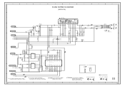
...:LES PIECES REPAREES PAR UN ETANT DANGEREUSES AN POINT DE VUE SECURITE N'UTILISER QUE CELLS DECRITES DANS LA NOMENCLATURE DES PIECES E F CAUTION: DIGITAL TRANSISTOR AUDIO SIGNAL(REC) CAUTION: DIGITAL TRANSISTOR G 2 1 PCBDH0 CEF276 H H-22 ATT.CONT.
...:LES PIECES REPAREES PAR UN ETANT DANGEREUSES AN POINT DE VUE SECURITE N'UTILISER QUE CELLS DECRITES DANS LA NOMENCLATURE DES PIECES E F CAUTION: DIGITAL TRANSISTOR AUDIO SIGNAL(REC) CAUTION: DIGITAL TRANSISTOR G 2 1 PCBDH0 CEF276 H H-22 ATT.CONT.
