

LC-30HV6U Operation Manual
Page 6
Contents IMPORTANT INFORMATION 1 Trademarks 2 DEAR SHARP CUSTOMER 3 IMPORTANT SAFETY PRECAUTIONS 3 Contents 6 Supplied accessories 7 Preparation 8 Where to...function 69 Using the TV remote control unit to place the System 8 Setting the System 9 Setting the AVC System with the stand ......... 11 Setting the Display on the wall 11 Removing the stand and speaker ...Using the remote control unit 13 Cautions regarding remote control unit ... 13 Part names 14 Display 14 AVC System 15 Remote control unit 16 Watching TV 17 Antennas 17 Cable converter/VCR connection 17 Outdoor antenna...
Contents IMPORTANT INFORMATION 1 Trademarks 2 DEAR SHARP CUSTOMER 3 IMPORTANT SAFETY PRECAUTIONS 3 Contents 6 Supplied accessories 7 Preparation 8 Where to...function 69 Using the TV remote control unit to place the System 8 Setting the System 9 Setting the AVC System with the stand ......... 11 Setting the Display on the wall 11 Removing the stand and speaker ...Using the remote control unit 13 Cautions regarding remote control unit ... 13 Part names 14 Display 14 AVC System 15 Remote control unit 16 Watching TV 17 Antennas 17 Cable converter/VCR connection 17 Outdoor antenna...

LC-30HV6U Operation Manual
Page 7
... DTV/SAT INFO VCR REC A POWER B C INPUT VOL RECEIVER D VOL RRMCGA203WJSA Page 13 Stand unit (for AVC System) (g1) "AA" size battery (g2) Page 13 System cable (g1) Cable clamp (Large g1, Small g1) LHLDW0110CEZZ (Large) LHLDZ0139CEZZ (... QACCD3097CEPZ Page 9 LC-30HV6U TINS-A929WJZZ NOTE • Always use the AC cord supplied with the Liquid Crystal Television and the one supplied with the AVC System for each respective unit. • AC cords enclosed in this product are provided with the product. SHARP ELECTRONICS CORPORATION 1300 Naperville...
... DTV/SAT INFO VCR REC A POWER B C INPUT VOL RECEIVER D VOL RRMCGA203WJSA Page 13 Stand unit (for AVC System) (g1) "AA" size battery (g2) Page 13 System cable (g1) Cable clamp (Large g1, Small g1) LHLDW0110CEZZ (Large) LHLDZ0139CEZZ (... QACCD3097CEPZ Page 9 LC-30HV6U TINS-A929WJZZ NOTE • Always use the AC cord supplied with the Liquid Crystal Television and the one supplied with the AVC System for each respective unit. • AC cords enclosed in this product are provided with the product. SHARP ELECTRONICS CORPORATION 1300 Naperville...
LC-30HV6U Operation Manual
Page 8
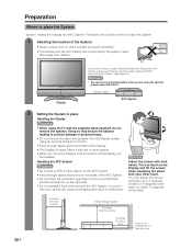
... space above and on the sides of the Display, not the speaker. First select the location where to keep a longer distance between the Display and AVC System, please purchase the optional system cable AN-07SC1 (about 23 feet/7 meters). (See page 81.) IMPORTANT • You cannot use external speakers when you... move the Display, hold the portion of the AVC System. • Do not block the ventilation openings on the top and left side, and the exhaust fan on the right side. • Do not...
... space above and on the sides of the Display, not the speaker. First select the location where to keep a longer distance between the Display and AVC System, please purchase the optional system cable AN-07SC1 (about 23 feet/7 meters). (See page 81.) IMPORTANT • You cannot use external speakers when you... move the Display, hold the portion of the AVC System. • Do not block the ventilation openings on the top and left side, and the exhaust fan on the right side. • Do not...
LC-30HV6U Operation Manual
Page 9
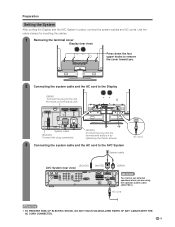
...) Press down the four upper hooks to remove the cover toward you. 2 Connecting the system cable and the AC cord to the AVC System System cable AC cord (BLACK) AVC System (rear view) (WHITE) (GRAY) IMPORTANT You cannot use external speakers when you are using the optional system cable (AN-07SC1). System... SHOCK, DO NOT TOUCH UN-INSULATED PARTS OF ANY CABLES WITH THE AC CORD CONNECTED. 9 Preparation Setting the System After putting the Display and the AVC System in place, connect the system cables and AC cords.
...) Press down the four upper hooks to remove the cover toward you. 2 Connecting the system cable and the AC cord to the AVC System System cable AC cord (BLACK) AVC System (rear view) (WHITE) (GRAY) IMPORTANT You cannot use external speakers when you are using the optional system cable (AN-07SC1). System... SHOCK, DO NOT TOUCH UN-INSULATED PARTS OF ANY CABLES WITH THE AC CORD CONNECTED. 9 Preparation Setting the System After putting the Display and the AVC System in place, connect the system cables and AC cords.

LC-30HV6U Operation Manual
Page 11
...details.) About setting the Display angle 5° • You can result in equipment failure. Stand cushion Attaching point Insert the stand into the AVC System, making sure that come with the big and small holes on the wall CAUTION • Installing the Liquid Crystal Television requires special skill... that results in accident or injury. SHARP bears no responsibility for improper mounting or mounting that should not attempt to do the work . Setting the Display on the...
...details.) About setting the Display angle 5° • You can result in equipment failure. Stand cushion Attaching point Insert the stand into the AVC System, making sure that come with the big and small holes on the wall CAUTION • Installing the Liquid Crystal Television requires special skill... that results in accident or injury. SHARP bears no responsibility for improper mounting or mounting that should not attempt to do the work . Setting the Display on the...

LC-30HV6U Operation Manual
Page 15
... it . See page 62 for expanded functionality in the diagram, lightly with the end of a ballpoint pen or other pointed object. Part names AVC System Headphone PC INPUT terminal (AUDIO) (When connecting headphones, the sound from the Front view PC INPUT terminal (ANALOG RGB) speakers is muted.)...indicator CLEAR* MAIN POWER button INPUT 4 terminals (AUDIO L/R) INPUT 4 terminal (VIDEO) INPUT 4 terminal (S-VIDEO) How to open the door. * If the AVC System is in standby mode (indicator lights red). • Pressing CLEAR will not work if the System is switched on but it does not appear...
... it . See page 62 for expanded functionality in the diagram, lightly with the end of a ballpoint pen or other pointed object. Part names AVC System Headphone PC INPUT terminal (AUDIO) (When connecting headphones, the sound from the Front view PC INPUT terminal (ANALOG RGB) speakers is muted.)...indicator CLEAR* MAIN POWER button INPUT 4 terminals (AUDIO L/R) INPUT 4 terminal (VIDEO) INPUT 4 terminal (S-VIDEO) How to open the door. * If the AVC System is in standby mode (indicator lights red). • Pressing CLEAR will not work if the System is switched on but it does not appear...
LC-30HV6U Operation Manual
Page 17
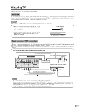
... lead-in an area with F-type connector that can view either TV programs or VCR tapes and not be concerned about the position of the AVC System. Signal reception may fail if improperly connected. • Be sure to remember what kind of connecting a VCR and CATV Converter to your TV if...
... lead-in an area with F-type connector that can view either TV programs or VCR tapes and not be concerned about the position of the AVC System. Signal reception may fail if improperly connected. • Be sure to remember what kind of connecting a VCR and CATV Converter to your TV if...
LC-30HV6U Operation Manual
Page 20
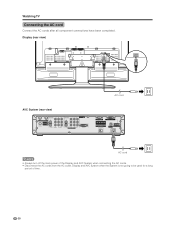
Watching TV Connecting the AC cord Connect the AC cords after all component connections have been completed. Display (rear view) AVC System (rear view) AC cord AC cord NOTE • Always turn off the main power of the Display and AVC System when connecting the AC cords. • Disconnect the AC cords from the AC outlet, Display and AVC System when the System is not going to be used for a long period of time. 20
Watching TV Connecting the AC cord Connect the AC cords after all component connections have been completed. Display (rear view) AVC System (rear view) AC cord AC cord NOTE • Always turn off the main power of the Display and AVC System when connecting the AC cords. • Disconnect the AC cords from the AC outlet, Display and AVC System when the System is not going to be used for a long period of time. 20

LC-30HV6U Operation Manual
Page 21
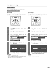
... button MAIN POWER POWER indicator 1 Press MAIN POWER on the Display. • The POWER indicator on the Display flashes red. 2 Press MAIN POWER on the AVC System. • The System turns the power on. • The POWER indicator on the Display lights up green and the STANDBY/ON indicator on the... control unit or POWER button on the Display to turn the System on for a long period of time, be invoked. First time turning on the AVC System AVC System MAIN STANDBY/ON indicator POWER TV POWER TV CBL VCR DVD /SAT /LD /DTV ANT-A/B INPUT AV Virtual MODE MTS CC VIEW MODE...
... button MAIN POWER POWER indicator 1 Press MAIN POWER on the Display. • The POWER indicator on the Display flashes red. 2 Press MAIN POWER on the AVC System. • The System turns the power on. • The POWER indicator on the Display lights up green and the STANDBY/ON indicator on the... control unit or POWER button on the Display to turn the System on for a long period of time, be invoked. First time turning on the AVC System AVC System MAIN STANDBY/ON indicator POWER TV POWER TV CBL VCR DVD /SAT /LD /DTV ANT-A/B INPUT AV Virtual MODE MTS CC VIEW MODE...

LC-30HV6U Operation Manual
Page 22
... B. 2 Press c/d to select the desired language listed on the screen, and then press SET/ ENTER. A, then press a/b to 19.) 3. B. Connect the antenna cable to the AVC System. (See pages 17 to move down. Plug in this operation manual are for explanation purposes and may vary slightly from among 3 languages: English, French...
... B. 2 Press c/d to select the desired language listed on the screen, and then press SET/ ENTER. A, then press a/b to 19.) 3. B. Connect the antenna cable to the AVC System. (See pages 17 to move down. Plug in this operation manual are for explanation purposes and may vary slightly from among 3 languages: English, French...
LC-30HV6U Operation Manual
Page 39
... Control ... NOTE • "Disable" is no signal inputs for 15 minutes. NOTE • "Disable" is factory preset value. • When a TV program finishes, and the AVC System receives signal input, this function may not operate. • Five minutes before the power shuts down if there is factory preset value. 39 Basic...
... Control ... NOTE • "Disable" is no signal inputs for 15 minutes. NOTE • "Disable" is factory preset value. • When a TV program finishes, and the AVC System receives signal input, this function may not operate. • Five minutes before the power shuts down if there is factory preset value. 39 Basic...

LC-30HV6U Operation Manual
Page 41
DVD player Digital TV tuner S-VIDEO AV Y/PB/PR S-VIDEO Y/PB/PR AV DVI AVC System (rear view) S-VIDEO AV VCR AV S-VIDEO AV Receiver (Built-in Tuner Amp) AVC System (front view) PC-AUDIO AV PC ANALOG RGB S-VIDEO Game console/ Camcorder CAUTION • To protect all equipment, ...always turn off the AVC System before making connections. 41 Using external equipment You can connect many types of external equipment to a DVD player, VCR, Digital TV tuner,...
DVD player Digital TV tuner S-VIDEO AV Y/PB/PR S-VIDEO Y/PB/PR AV DVI AVC System (rear view) S-VIDEO AV VCR AV S-VIDEO AV Receiver (Built-in Tuner Amp) AVC System (front view) PC-AUDIO AV PC ANALOG RGB S-VIDEO Game console/ Camcorder CAUTION • To protect all equipment, ...always turn off the AVC System before making connections. 41 Using external equipment You can connect many types of external equipment to a DVD player, VCR, Digital TV tuner,...

LC-30HV6U Operation Manual
Page 42
... 1 terminal when connecting to your DVD player operation manual for "Input Select" in the "Option" menu. (See page 52.) For INPUT1 signal TV MENU [Option ... AVC System (rear view) Component video cable (commercially available) When using INPUT on the remote control unit or on the Display. (See page 52.) The setting...
... 1 terminal when connecting to your DVD player operation manual for "Input Select" in the "Option" menu. (See page 52.) For INPUT1 signal TV MENU [Option ... AVC System (rear view) Component video cable (commercially available) When using INPUT on the remote control unit or on the Display. (See page 52.) The setting...

LC-30HV6U Operation Manual
Page 43
... INPUT 2 terminals, select "INPUT2". INPUT SOURCE TV INPUT1 INPUT2 INPUT3 INPUT4 PC You only need to your VCR operation manual for the signal type. 43 AVC System (rear view) TV POWER TV CBL VCR DVD /SAT /LD /DTV ANT-A/B INPUT AV Virtual MODE MTS CC VIEW MODE TWIN PICTURE FREEZE SELECT...
... INPUT 2 terminals, select "INPUT2". INPUT SOURCE TV INPUT1 INPUT2 INPUT3 INPUT4 PC You only need to your VCR operation manual for the signal type. 43 AVC System (rear view) TV POWER TV CBL VCR DVD /SAT /LD /DTV ANT-A/B INPUT AV Virtual MODE MTS CC VIEW MODE TWIN PICTURE FREEZE SELECT...
LC-30HV6U Operation Manual
Page 44
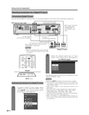
...on "Input Select" in the menu. NOTE • When the device has a 15-pin terminal, use a commercially available D-sub cable to connect it. AVC System (rear view) Component video cable (commercially available) When using component video cable, select "COMPONENT" for "Input Select" in the "Option" menu. (See... COMPONENT AV-Y/C DVI INPUT button Displaying broadcasts via a Digital TV tuner Connecting a Digital TV tuner You can be selected on the front of the AVC System when connecting a PC. (See page 46.) • When connecting to the DVI-HDTV INPUT terminal, be sure to use the INPUT 3...
...on "Input Select" in the menu. NOTE • When the device has a 15-pin terminal, use a commercially available D-sub cable to connect it. AVC System (rear view) Component video cable (commercially available) When using component video cable, select "COMPONENT" for "Input Select" in the "Option" menu. (See... COMPONENT AV-Y/C DVI INPUT button Displaying broadcasts via a Digital TV tuner Connecting a Digital TV tuner You can be selected on the front of the AVC System when connecting a PC. (See page 46.) • When connecting to the DVI-HDTV INPUT terminal, be sure to use the INPUT 3...

LC-30HV6U Operation Manual
Page 45
AVC System (front view) TV POWER AV MODE VIEW MODE TV CBL VCR DVD /SAT /LD /DTV ANT-A/B INPUT Virtual MTS CC TWIN PICTURE FREEZE SELECT ...
AVC System (front view) TV POWER AV MODE VIEW MODE TV CBL VCR DVD /SAT /LD /DTV ANT-A/B INPUT Virtual MTS CC TWIN PICTURE FREEZE SELECT ...

LC-30HV6U Operation Manual
Page 46
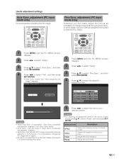
... terminals to connect a PC. adjustment on the "Auto Sync." INPUT SOURCE TV INPUT1 INPUT2 INPUT3 INPUT4 PC You only need to set the Auto Sync. AVC System (front view) RGB cable (commercially available) PC ø 3.5 mm stereo minijack cable (commercially available) Signal names for 15-pin mini D-sub connecter 543 21...
... terminals to connect a PC. adjustment on the "Auto Sync." INPUT SOURCE TV INPUT1 INPUT2 INPUT3 INPUT4 PC You only need to set the Auto Sync. AVC System (front view) RGB cable (commercially available) PC ø 3.5 mm stereo minijack cable (commercially available) Signal names for 15-pin mini D-sub connecter 543 21...
LC-30HV6U Operation Manual
Page 51
... you can easily adjust the picture as necessary to change the PC image and try again. • Be sure to connect the PC to the AVC System and switch it to the left or right. is needed to your desired position. If not, Auto Sync. failed. • Auto Sync. If not...
... you can easily adjust the picture as necessary to change the PC image and try again. • Be sure to connect the PC to the AVC System and switch it to the left or right. is needed to your desired position. If not, Auto Sync. failed. • Auto Sync. If not...
LC-30HV6U Operation Manual
Page 67
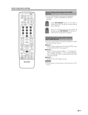
... reactivate BLOCK. At this time V- Method 1: Select "Status" setting from the Parental CTRL to reactivate BLOCK. See pages 64 and 66. Method 3: Switch off the AVC System power. NOTE • Performing any of the three above will activate the V-CHIP BLOCK. 67 CHIP BLOCK temporarily releases. Method 2: Select "V-Chip" setting ("MPAA...
... reactivate BLOCK. At this time V- Method 1: Select "Status" setting from the Parental CTRL to reactivate BLOCK. See pages 64 and 66. Method 3: Switch off the AVC System power. NOTE • Performing any of the three above will activate the V-CHIP BLOCK. 67 CHIP BLOCK temporarily releases. Method 2: Select "V-Chip" setting ("MPAA...
LC-30HV6U Operation Manual
Page 77
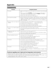
...8226; Is the AC cord disconnected? (See page 20.) • Has the main power been turned on the power of the Display and the AVC System, or unplugging the AC cord and replugging it under strong or fluorescent lighting? • Is a fluorescent light illuminated near a heater, as ...cut off . • Is the sleep timer set correctly? Appendix Troubleshooting Problem • No power Possible Solution • Make sure the Display and the AVC System are connected correctly. (See page 9.) • Check if you using it in after connection? (See page 52.) • Is the correct input...
...8226; Is the AC cord disconnected? (See page 20.) • Has the main power been turned on the power of the Display and the AVC System, or unplugging the AC cord and replugging it under strong or fluorescent lighting? • Is a fluorescent light illuminated near a heater, as ...cut off . • Is the sleep timer set correctly? Appendix Troubleshooting Problem • No power Possible Solution • Make sure the Display and the AVC System are connected correctly. (See page 9.) • Check if you using it in after connection? (See page 52.) • Is the correct input...


