

Service Manual
Page 1
...R/C, LED Unit 10-52 [6] KEY Unit 10-53 Parts Guide CHAPTER 6. OPERATION MANUAL [1] OPERATION MANUAL 2-1 CHAPTER 3. DIMENSIONS [1] DIMENSIONS 3-1 CHAPTER 4. SCHEMATIC DIAGRAM [1] DESCRIPTION OF SCHEMATIC DIA- This document has been published to replace these parts with " " are subject to those specified should be used . TopPage LC-32HT2U SERVICE MANUAL No. MAJOR IC INFORMATIONS [1] MAJOR IC INFORMATIONS 7-1 Parts marked with specified ones for maintaining the safety of the set. SPECIFICATIONS [1] SPECIFICATIONS 1-1 CHAPTER 2. REMOVING OF MAJOR PARTS [1] REMOVING...
...R/C, LED Unit 10-52 [6] KEY Unit 10-53 Parts Guide CHAPTER 6. OPERATION MANUAL [1] OPERATION MANUAL 2-1 CHAPTER 3. DIMENSIONS [1] DIMENSIONS 3-1 CHAPTER 4. SCHEMATIC DIAGRAM [1] DESCRIPTION OF SCHEMATIC DIA- This document has been published to replace these parts with " " are subject to those specified should be used . TopPage LC-32HT2U SERVICE MANUAL No. MAJOR IC INFORMATIONS [1] MAJOR IC INFORMATIONS 7-1 Parts marked with specified ones for maintaining the safety of the set. SPECIFICATIONS [1] SPECIFICATIONS 1-1 CHAPTER 2. REMOVING OF MAJOR PARTS [1] REMOVING...

Service Manual
Page 2
... factory recommended replacement parts shown in the following safety checks: DVM AC SCALE 1.5k ohm 10W 3. LC-32HT2U LSCA-32FHET2TUY PRECAUTION Service Manual IMPORTANT SERVICE SAFETY PRECAUTION Service work should be attempted. 2. Disconnect AC power before returning the monitor to the owner. „BEFORE RETURNING THE RECEIVER (Fire & Shock Hazard) Before returning the receiver to make certain that no modification of a substitute replacement parts which must be used...
... factory recommended replacement parts shown in the following safety checks: DVM AC SCALE 1.5k ohm 10W 3. LC-32HT2U LSCA-32FHET2TUY PRECAUTION Service Manual IMPORTANT SERVICE SAFETY PRECAUTION Service work should be attempted. 2. Disconnect AC power before returning the monitor to the owner. „BEFORE RETURNING THE RECEIVER (Fire & Shock Hazard) Before returning the receiver to make certain that no modification of a substitute replacement parts which must be used...
Service Manual
Page 4
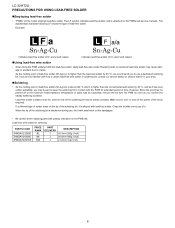
...replacing parts with polarity indication on and off or the maximum heat-resistance temperature of parts may be apt to turn on the PWB silk. Indicates lead-free solder of tin, silver and copper. „Using lead-free wire solder • When fixing the PWB soldered with the PWB for servicing PARTS CODE...-free solder, apply lead-free wire solder. If a different type of solder stays on the PWBs and service manuals. Repairing with lead-free solder. LC-32HT2U PRECAUTIONS FOR USING LEAD-FREE SOLDER „Employing lead-free solder • "PWBs" of lead-free solder. Lead-free solder...
...replacing parts with polarity indication on and off or the maximum heat-resistance temperature of parts may be apt to turn on the PWB silk. Indicates lead-free solder of tin, silver and copper. „Using lead-free wire solder • When fixing the PWB soldered with the PWB for servicing PARTS CODE...-free solder, apply lead-free wire solder. If a different type of solder stays on the PWBs and service manuals. Repairing with lead-free solder. LC-32HT2U PRECAUTIONS FOR USING LEAD-FREE SOLDER „Employing lead-free solder • "PWBs" of lead-free solder. Lead-free solder...
Service Manual
Page 5
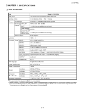
.... SPECIFICATIONS [1] SPECIFICATIONS Service Manual LC-32HT2U Item Model: LC-32HT2U LCD panel 32" Advanced Super View & BLACK TFT LCD Number of production units. There may be some deviations from these values in with HDCP ANTENNA 75 Unbalance, F Type 1 (VHF/UHF/CATV/ATSC/QAM) DIGITAL AUDIO OUTPUT Optical Digital audio output 1 (PCM/Dolby Digital) OUTPUT Audio out TRANSPORT RJ-11 OSD language English/French/Spanish Power Requirement AC 120 V, 60 Hz Power Consumption 164 W Weight w/o stand with stand Dimension (W H D) w/o stand with stand Operating temperature...
.... SPECIFICATIONS [1] SPECIFICATIONS Service Manual LC-32HT2U Item Model: LC-32HT2U LCD panel 32" Advanced Super View & BLACK TFT LCD Number of production units. There may be some deviations from these values in with HDCP ANTENNA 75 Unbalance, F Type 1 (VHF/UHF/CATV/ATSC/QAM) DIGITAL AUDIO OUTPUT Optical Digital audio output 1 (PCM/Dolby Digital) OUTPUT Audio out TRANSPORT RJ-11 OSD language English/French/Spanish Power Requirement AC 120 V, 60 Hz Power Consumption 164 W Weight w/o stand with stand Dimension (W H D) w/o stand with stand Operating temperature...

Service Manual
Page 6
OPERATION MANUAL [1] OPERATION MANUAL Service Manual 2 - 1 Part names TV (Front) Channel buttons (CH / ) Volume buttons ( VOL - /+ ) INPUT button POWER button Remote control sensor POWER indicator** OPC indicator* OPC sensor* NOTE * OPC: Optical Picture Control. ** for other purposes. Do not use it for TV status indicator. Part names TV (Rear) DVI terminal (INPUT 5) DIGITAL AUDIO OUTPUT terminal DVI AUDIO terminal (INPUT 5) AUDIO input terminals (INPUT 4) HDMI terminal (INPUT 3) HDMI terminal (INPUT 4) TRANSPORT terminal* Antenna/Cable in INPUT 2 terminals AUDIO OUTPUT...
OPERATION MANUAL [1] OPERATION MANUAL Service Manual 2 - 1 Part names TV (Front) Channel buttons (CH / ) Volume buttons ( VOL - /+ ) INPUT button POWER button Remote control sensor POWER indicator** OPC indicator* OPC sensor* NOTE * OPC: Optical Picture Control. ** for other purposes. Do not use it for TV status indicator. Part names TV (Rear) DVI terminal (INPUT 5) DIGITAL AUDIO OUTPUT terminal DVI AUDIO terminal (INPUT 5) AUDIO input terminals (INPUT 4) HDMI terminal (INPUT 3) HDMI terminal (INPUT 4) TRANSPORT terminal* Antenna/Cable in INPUT 2 terminals AUDIO OUTPUT...

Service Manual
Page 7
... Digital Noise Reduction Output Select Caption Setup Program Title Display Audio Setup Specification Digital Setup No Signal Off No Operation Off Power Control Input Skip Input Label Position Standby Mode Language Reset Setup Option Audio Only Digital Noise Reduction HDMI Setup Output Select LC-32HT2U 2 - 2 Quick Reference Attaching the stand Before attaching (or detaching) the stand, unplug the AC cord from being damaged. Be sure to lay the TV on the bottom of the stand may result in the TV falling over the base...
... Digital Noise Reduction Output Select Caption Setup Program Title Display Audio Setup Specification Digital Setup No Signal Off No Operation Off Power Control Input Skip Input Label Position Standby Mode Language Reset Setup Option Audio Only Digital Noise Reduction HDMI Setup Output Select LC-32HT2U 2 - 2 Quick Reference Attaching the stand Before attaching (or detaching) the stand, unplug the AC cord from being damaged. Be sure to lay the TV on the bottom of the stand may result in the TV falling over the base...

Service Manual
Page 15
....jp/support/audio/sd/download/sd_formatter_e.html) Preparations To upgrade the main software, it is necessary to the following software. • Main software • Monitor microprocessor software The main software and the monitor microprocessor software can be damaged beyond recovery. 2.1. Main software version upgrade Get ready before shipping. Click [Format]. (When you have the drive options, select the drive where the SD card is ongoing. ADJUSTMENT Service Manual LC-32HT2U [1] ADJUSTMENT...
....jp/support/audio/sd/download/sd_formatter_e.html) Preparations To upgrade the main software, it is necessary to the following software. • Main software • Monitor microprocessor software The main software and the monitor microprocessor software can be damaged beyond recovery. 2.1. Main software version upgrade Get ready before shipping. Click [Format]. (When you have the drive options, select the drive where the SD card is ongoing. ADJUSTMENT Service Manual LC-32HT2U [1] ADJUSTMENT...

Service Manual
Page 18
...) into the service socket located lower side from center at terminals, above S-VIDEO terminal in the rear of the unit, in a wrong way, the card will go to the unit (unplug the AC cord), and remove the SD card for monitor microprocessor software version upgrade in the "Main software version upgrade". Turn on this operation is troubled. 6. Otherwise the upgrade will trigger the upgrade failure screen. NOTE...
...) into the service socket located lower side from center at terminals, above S-VIDEO terminal in the rear of the unit, in a wrong way, the card will go to the unit (unplug the AC cord), and remove the SD card for monitor microprocessor software version upgrade in the "Main software version upgrade". Turn on this operation is troubled. 6. Otherwise the upgrade will trigger the upgrade failure screen. NOTE...
Service Manual
Page 19
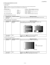
...-p (Pedestal to VIDEO 1 input. Entering the adjustment process mode Adjustment item Adjustment conditions Adjustment procedure 1 Adjustment pro- 2.4. cess mode 3. Adjustment procedure Feed the 100% color bar signal to TUNER. [Video input signal] [US-10CH] 75% color saturation 100% white 100% white 2 Auto adjustment Page 3 performance 4. Device check Before adjustment, make sure that the adjusting device and signal source are set for the Sharp LCD US. Component 15K signal adjustment Adjustment item Adjustment conditions 1 Adjustment 480i signal Bring the cursor...
...-p (Pedestal to VIDEO 1 input. Entering the adjustment process mode Adjustment item Adjustment conditions Adjustment procedure 1 Adjustment pro- 2.4. cess mode 3. Adjustment procedure Feed the 100% color bar signal to TUNER. [Video input signal] [US-10CH] 75% color saturation 100% white 100% white 2 Auto adjustment Page 3 performance 4. Device check Before adjustment, make sure that the adjusting device and signal source are set for the Sharp LCD US. Component 15K signal adjustment Adjustment item Adjustment conditions 1 Adjustment 480i signal Bring the cursor...

Service Manual
Page 26
... values. LC-32HT2U PC Set Start measurement Repeat until RGB become the target values. Password data 4. Version confirmation screen appears. [SUCCESS] on a green line indicates that the setting is the parameter value of an error, [ERROR] and an error code appear on the power after the shipping setting. broadcast frequencies) 3. Adjust RB to factory settings After the shipping setting, pull off with zero fill). * G is fixed. * The default adjustment value...
... values. LC-32HT2U PC Set Start measurement Repeat until RGB become the target values. Password data 4. Version confirmation screen appears. [SUCCESS] on a green line indicates that the setting is the parameter value of an error, [ERROR] and an error code appear on the power after the shipping setting. broadcast frequencies) 3. Adjust RB to factory settings After the shipping setting, pull off with zero fill). * G is fixed. * The default adjustment value...
Service Manual
Page 27
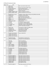
... sensor Number of lamp error Reasons of standby at normal time Reasons of standby in the event of error 2 1 INDUSTRY INIT (+Cause) 2 INDUSTRY INIT 3 HOTELMODE 4 Center Acutime 5 RESET 6 BacklightAcutime 7 RESET 8 LAMP ERROR RESET 9 VIC XPOS 10 VIC YPOS 11 VIC COLOR 12 VIC SIGNAL TYPE 13 VIC READ Initialization to factory settings (including clearing Standby Cause data) Initialization to factory settings Activate/deactivate the hotel mode Main microcomputer operating time Reset main microcomputer operating time...
... sensor Number of lamp error Reasons of standby at normal time Reasons of standby in the event of error 2 1 INDUSTRY INIT (+Cause) 2 INDUSTRY INIT 3 HOTELMODE 4 Center Acutime 5 RESET 6 BacklightAcutime 7 RESET 8 LAMP ERROR RESET 9 VIC XPOS 10 VIC YPOS 11 VIC COLOR 12 VIC SIGNAL TYPE 13 VIC READ Initialization to factory settings (including clearing Standby Cause data) Initialization to factory settings Activate/deactivate the hotel mode Main microcomputer operating time Reset main microcomputer operating time...

Service Manual
Page 30
... 3 STANDBY CAUSE RESET 2.9. Code list for Standby Cause Code 1 2 5 6 7 8 9 A B C Indication RC_STNBY E_CCKMVT OUT_OF_R NO_OPERT NO_SIGNA PC_MODE1 PC_MODE2 SLEEP_TM E_NOMONI OFF_232C Description /* Standby set by remote control */ /* Abnormal voltage of CCKM line detected */ "/* While a PC display is on, unspecified input continued long time. */" /* Off caused by no operation */ /* Off caused by no signal */ /* Set by the PC power management mode 1 */ /* Set by the PC power management mode 2 */ /* Set by off timer */ /* Incompatible monitor is connected to...
... 3 STANDBY CAUSE RESET 2.9. Code list for Standby Cause Code 1 2 5 6 7 8 9 A B C Indication RC_STNBY E_CCKMVT OUT_OF_R NO_OPERT NO_SIGNA PC_MODE1 PC_MODE2 SLEEP_TM E_NOMONI OFF_232C Description /* Standby set by remote control */ /* Abnormal voltage of CCKM line detected */ "/* While a PC display is on, unspecified input continued long time. */" /* Off caused by no operation */ /* Off caused by no signal */ /* Set by the PC power management mode 1 */ /* Set by the PC power management mode 2 */ /* Set by off timer */ /* Incompatible monitor is connected to...

Service Manual
Page 32
... Television Mode screen shows up . Now the set will be turned off . NO Disconnect cable between STB and TV. Press MASTER button on Remote Replicator. *1 Press MENU button on the Remote Replicator. Change to TV. Wait until TV is turned off automatically soon. 8. Select MENU, PPV TV and TV MODE in the AC power cord. 3. The power is not connected to Normal TV mode. 5 - 18 Select Normal TV. 6. LC-32HT2U [2] HOW TO SWITCH...
... Television Mode screen shows up . Now the set will be turned off . NO Disconnect cable between STB and TV. Press MASTER button on Remote Replicator. *1 Press MENU button on the Remote Replicator. Change to TV. Wait until TV is turned off automatically soon. 8. Select MENU, PPV TV and TV MODE in the AC power cord. 3. The power is not connected to Normal TV mode. 5 - 18 Select Normal TV. 6. LC-32HT2U [2] HOW TO SWITCH...

Service Manual
Page 33
.... 2. Press the MASTER button on Remote Controller. The power will power off after the TV mode change from Normal TV mode to TV. NO Disconnect cable between STB and TV. 2. Now the set will be turned off . How to Hotel TV mode. *1: used option Remote Replicator [AN-H05RCU] *2: used option Remote Controller [AN-32HTRC] LC-32HT2U YES *2 *1 5 - 19 Press MASTER button on the power. 4. Change to change ] appears. Press POWER button on the Remote Replicator. 5. [TV...
.... 2. Press the MASTER button on Remote Controller. The power will power off after the TV mode change from Normal TV mode to TV. NO Disconnect cable between STB and TV. 2. Now the set will be turned off . How to Hotel TV mode. *1: used option Remote Replicator [AN-H05RCU] *2: used option Remote Controller [AN-32HTRC] LC-32HT2U YES *2 *1 5 - 19 Press MASTER button on the power. 4. Change to change ] appears. Press POWER button on the Remote Replicator. 5. [TV...

Service Manual
Page 34
... 6 - 1 Is 24V supplied? LC-32HT2U LCC-H32AHT2PUTER 6. TROUBLE SHOOTING TABLSEervice Manual [1] TROUBLE SHOOTING TABLE No power supply (Front LED does not light up) and no power-up even is blown when turning on (Front LED light up to STANDBY MODE2? NO Connect the AC cord and turn on the secondary side short-circuited? NO YES Is BU5V supplied? NO If the fuse is turned on the power after replacing F701, replace VZ701, DS4701, F4701...
... 6 - 1 Is 24V supplied? LC-32HT2U LCC-H32AHT2PUTER 6. TROUBLE SHOOTING TABLSEervice Manual [1] TROUBLE SHOOTING TABLE No power supply (Front LED does not light up) and no power-up even is blown when turning on (Front LED light up to STANDBY MODE2? NO Connect the AC cord and turn on the secondary side short-circuited? NO YES Is BU5V supplied? NO If the fuse is turned on the power after replacing F701, replace VZ701, DS4701, F4701...

Service Manual
Page 41
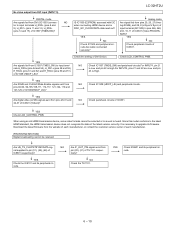
... circuits of the latest version correctly. Are cables connected securely? YES Are digital video (LVDS) signals sent from IC1507 (TMDS_SW) to upgrade its firmware. NO Check IC1501 and peripheral circuits. NO Check IC1507 (TMDS_SW) and peripheral circuits. When using an old HDMI transmission device, some video formats cannot be selected or no sound is necessary to input terminals H_RX0± (pins 54 and...
... circuits of the latest version correctly. Are cables connected securely? YES Are digital video (LVDS) signals sent from IC1507 (TMDS_SW) to upgrade its firmware. NO Check IC1501 and peripheral circuits. NO Check IC1507 (TMDS_SW) and peripheral circuits. When using an old HDMI transmission device, some video formats cannot be selected or no sound is necessary to input terminals H_RX0± (pins 54 and...

Service Manual
Page 42
... the customer service center of IC1508 (HDCP_LSI)? For INPUT5, pins 21 and 22 are Low and pin 23 is heard. NO Is IC1502 (E2PROM) accessed with I2C when connecting HDMI device and is DDC_I2C _CLOCK/DATA data read out? NO Check IC1502 and peripheral circuits. LC-32HT2U No video output from HDMI input (INPUT4) INPUT4 Are signals fed from HDMI (SC1502) connector...
... the customer service center of IC1508 (HDCP_LSI)? For INPUT5, pins 21 and 22 are Low and pin 23 is heard. NO Is IC1502 (E2PROM) accessed with I2C when connecting HDMI device and is DDC_I2C _CLOCK/DATA data read out? NO Check IC1502 and peripheral circuits. LC-32HT2U No video output from HDMI input (INPUT4) INPUT4 Are signals fed from HDMI (SC1502) connector...
Service Manual
Page 43
... 51) of each manufacturer, or contact the customer service center of IC1508 (HDCP_LSI)? YES YES NO Check IC1505 and peripheral circuits.Are cable connected securely? YES Are signals fed from pin (20), (21) of IC3301 (Video PROCES- When using an old HDMI transmission device, some video formats cannot be received. Download the latest firmware from pins 92-96, 99-105,108-111...
... 51) of each manufacturer, or contact the customer service center of IC1508 (HDCP_LSI)? YES YES NO Check IC1505 and peripheral circuits.Are cable connected securely? YES Are signals fed from pin (20), (21) of IC3301 (Video PROCES- When using an old HDMI transmission device, some video formats cannot be received. Download the latest firmware from pins 92-96, 99-105,108-111...

Service Manual
Page 45
..., error standby is activated. (MONITOR MAX TEMP on process A mode: Change of temperature failure AD value): Thermistor 2) Power failure details (Power LED flashes twice and OPC LED flashes) Error type Power red LED operation (1 cycle) PS_ON H: On 13V/UR10V failure Flashes once L: Off EU_POW H: On Main 3.3V failure Flashes twice D_POW L: Off H: On UR6V failure Flashes 3 times L: Off D_POW Digital 3.3V failure H: On Flashes 4 times L: Off PANEL_POW Panel 5V failure Flashes 5 times H: On L: Off Main failure H: On Flashes 7 times...
..., error standby is activated. (MONITOR MAX TEMP on process A mode: Change of temperature failure AD value): Thermistor 2) Power failure details (Power LED flashes twice and OPC LED flashes) Error type Power red LED operation (1 cycle) PS_ON H: On 13V/UR10V failure Flashes once L: Off EU_POW H: On Main 3.3V failure Flashes twice D_POW L: Off H: On UR6V failure Flashes 3 times L: Off D_POW Digital 3.3V failure H: On Flashes 4 times L: Off PANEL_POW Panel 5V failure Flashes 5 times H: On L: Off Main failure H: On Flashes 7 times...

Service Manual
Page 144
Top Cover X Power Button X Operation Button X Power Button Spring X Stand Support Ass'y X Support Cover X Stand Support X Screw Guide, x4 X Stand Base Ass'y X Stand Base Cover X Base Angle X LEG Cushion-A, x4 X LEG Cushion-B, x4 X Screw, x10 J 32" WIDE LCD Panel Module Unit - IF Unit - KEY Unit X POWER SUPPLY Unit X SD Card Cover X LED Cover X Stand Cover X Jack Indicator X MODEL Label X Jack Angle Long X Center Angle-R X Center Angle-L X Center Assist Angle X Rug Angle Top, x2 X Rug Angle Bottom-R X Rug...
Top Cover X Power Button X Operation Button X Power Button Spring X Stand Support Ass'y X Support Cover X Stand Support X Screw Guide, x4 X Stand Base Ass'y X Stand Base Cover X Base Angle X LEG Cushion-A, x4 X LEG Cushion-B, x4 X Screw, x10 J 32" WIDE LCD Panel Module Unit - IF Unit - KEY Unit X POWER SUPPLY Unit X SD Card Cover X LED Cover X Stand Cover X Jack Indicator X MODEL Label X Jack Angle Long X Center Angle-R X Center Angle-L X Center Assist Angle X Rug Angle Top, x2 X Rug Angle Bottom-R X Rug...


