
LC-37HV6U Operation Manual
Page 7
adjustment (PC input mode only) ... 51 Fine Sync. Contents IMPORTANT INFORMATION 1 Trademarks 2 DEAR SHARP CUSTOMER 3 IMPORTANT SAFETY PRECAUTIONS 3 Contents 6 Supplied accessories 7 Preparation 8 Where to control other devices 70 Appendix 76 Troubleshooting 76 PC compatibility chart ...speaker 12 Inserting the batteries 13 Using the remote control unit 13 Cautions regarding remote control unit ... 13 Part names 14 Display 14 AVC System 15 Remote control unit 16 Watching TV 17 Antennas 17 Cable converter/VCR connection 17 Outdoor antenna connection 19 Connecting the AC ...
adjustment (PC input mode only) ... 51 Fine Sync. Contents IMPORTANT INFORMATION 1 Trademarks 2 DEAR SHARP CUSTOMER 3 IMPORTANT SAFETY PRECAUTIONS 3 Contents 6 Supplied accessories 7 Preparation 8 Where to control other devices 70 Appendix 76 Troubleshooting 76 PC compatibility chart ...speaker 12 Inserting the batteries 13 Using the remote control unit 13 Cautions regarding remote control unit ... 13 Part names 14 Display 14 AVC System 15 Remote control unit 16 Watching TV 17 Antennas 17 Cable converter/VCR connection 17 Outdoor antenna connection 19 Connecting the AC ...
LC-37HV6U Operation Manual
Page 8
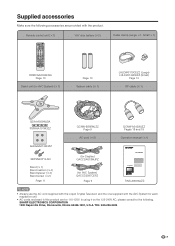
... Stand (g1) Stand cushion (g4) Stand spacer (g4) Stand screw (g2) Page 11 (for Display) QACCDA019WJPZ (for AVC System) QACCD3097CEPZ Page 9 LC-37HV6U TINS-A904WJZZ NOTE • Always use the AC cord supplied with the Liquid Crystal Television and the one supplied with the product...following accessories are for each respective unit. • AC cords enclosed in this product are provided with the AVC System for 110-125V. SHARP ELECTRONICS CORPORATION 1300 Naperville Drive, Romeoville, Illinois 60446-1091, U.S.A. Supplied accessories Make sure the following . TEL: 630-226...
... Stand (g1) Stand cushion (g4) Stand spacer (g4) Stand screw (g2) Page 11 (for Display) QACCDA019WJPZ (for AVC System) QACCD3097CEPZ Page 9 LC-37HV6U TINS-A904WJZZ NOTE • Always use the AC cord supplied with the Liquid Crystal Television and the one supplied with the product...following accessories are for each respective unit. • AC cords enclosed in this product are provided with the AVC System for 110-125V. SHARP ELECTRONICS CORPORATION 1300 Naperville Drive, Romeoville, Illinois 60446-1091, U.S.A. Supplied accessories Make sure the following . TEL: 630-226...

LC-37HV6U Operation Manual
Page 9
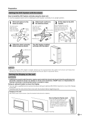
...the stand with the supplied stand attached, do not remove the speaker. First select the location where to keep a longer distance between the Display and AVC System, please purchase the optional system cable AN-07SC1 (about 23 feet/7 meters). (See page 80.) IMPORTANT • You cannot use external ...and speaker from the Display unless using an optional bracket to mount it with no direct sunlight and good ventilation. • The Display and the AVC System are using the TV with your other device on the right side. 8 Preparation Where to 4 degrees forward or 6 degrees backward, or ...
...the stand with the supplied stand attached, do not remove the speaker. First select the location where to keep a longer distance between the Display and AVC System, please purchase the optional system cable AN-07SC1 (about 23 feet/7 meters). (See page 80.) IMPORTANT • You cannot use external ...and speaker from the Display unless using an optional bracket to mount it with no direct sunlight and good ventilation. • The Display and the AVC System are using the TV with your other device on the right side. 8 Preparation Where to 4 degrees forward or 6 degrees backward, or ...

LC-37HV6U Operation Manual
Page 10
...(GRAY) Connect the plug firmly until the hooks on both sides click. 3 Connecting the system cable and the AC cord to the AVC System System cable (BLACK) AVC System (rear view) (WHITE) (GRAY) IMPORTANT You cannot use external speakers when you . 2 Connecting the system cable and the ...cover toward you. AC cord (with ferrite core) (BLACK) Connect the plug completely. Preparation Setting the System After putting the Display and the AVC System in place, connect the system cables and AC cords. Use the cable clamps for bundling the cables. 1 Removing the terminal cover Display ...
...(GRAY) Connect the plug firmly until the hooks on both sides click. 3 Connecting the system cable and the AC cord to the AVC System System cable (BLACK) AVC System (rear view) (WHITE) (GRAY) IMPORTANT You cannot use external speakers when you . 2 Connecting the system cable and the ...cover toward you. AC cord (with ferrite core) (BLACK) Connect the plug completely. Preparation Setting the System After putting the Display and the AVC System in place, connect the system cables and AC cords. Use the cable clamps for bundling the cables. 1 Removing the terminal cover Display ...
LC-37HV6U Operation Manual
Page 12
.... Do not set the Display on the wall up to 5 degrees forward when the speaker is not attached. Stand screw NOTE • When mounting the AVC System vertically, always use the supplied stand. Thin bulge Bulge Attaching point Small hole Big hole Thick bulge 4 Attach the stand using the stand screws... angle 5° • You can ask a qualified service personnel about using an optional AN-37AG1 bracket to mount the Display to the stand as shown. SHARP bears no responsibility for improper mounting or mounting that come with the stand.
.... Do not set the Display on the wall up to 5 degrees forward when the speaker is not attached. Stand screw NOTE • When mounting the AVC System vertically, always use the supplied stand. Thin bulge Bulge Attaching point Small hole Big hole Thick bulge 4 Attach the stand using the stand screws... angle 5° • You can ask a qualified service personnel about using an optional AN-37AG1 bracket to mount the Display to the stand as shown. SHARP bears no responsibility for improper mounting or mounting that come with the stand.

LC-37HV6U Operation Manual
Page 16
...pen or other pointed object. Rear view DC OUTPUT terminal (Terminal for clearing the secret number when you forget your secret number. Part names AVC System Headphone PC INPUT terminal (AUDIO) (When connecting headphones, the sound from the Front view PC INPUT terminal (ANALOG RGB) speakers is muted... CLEAR* MAIN POWER button INPUT 4 terminals (AUDIO L/R) INPUT 4 terminal (VIDEO) INPUT 4 terminal (S-VIDEO) How to open the door. * If the AVC System is in standby mode (indicator lights red). • Pressing CLEAR will not work if the System is switched on but it does not appear...
...pen or other pointed object. Rear view DC OUTPUT terminal (Terminal for clearing the secret number when you forget your secret number. Part names AVC System Headphone PC INPUT terminal (AUDIO) (When connecting headphones, the sound from the Front view PC INPUT terminal (ANALOG RGB) speakers is muted... CLEAR* MAIN POWER button INPUT 4 terminals (AUDIO L/R) INPUT 4 terminal (VIDEO) INPUT 4 terminal (S-VIDEO) How to open the door. * If the AVC System is in standby mode (indicator lights red). • Pressing CLEAR will not work if the System is switched on but it does not appear...

LC-37HV6U Operation Manual
Page 18
... Cable (commercially available) S-video Cable (commercially available) NOTE • Be sure to remember what kind of connection is a brief explanation of the types of the AVC System. If your VCR has an S-Video terminal, S-video connection is a flat "twin-lead" cable that can be attached to a terminal without tools (not supplied...
... Cable (commercially available) S-video Cable (commercially available) NOTE • Be sure to remember what kind of connection is a brief explanation of the types of the AVC System. If your VCR has an S-Video terminal, S-video connection is a flat "twin-lead" cable that can be attached to a terminal without tools (not supplied...
LC-37HV6U Operation Manual
Page 21
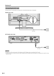
Display (rear view) AVC System (rear view) AC cord AC cord NOTE • Always turn off the main power of the Display and AVC System when connecting the AC cords. • Disconnect the AC cords from the AC outlet, Display and AVC System when the System is not going to be used for a long period of time. 20 Watching TV Connecting the AC cord Connect the AC cords after all component connections have been completed.
Display (rear view) AVC System (rear view) AC cord AC cord NOTE • Always turn off the main power of the Display and AVC System when connecting the AC cords. • Disconnect the AC cords from the AC outlet, Display and AVC System when the System is not going to be used for a long period of time. 20 Watching TV Connecting the AC cord Connect the AC cords after all component connections have been completed.

LC-37HV6U Operation Manual
Page 22
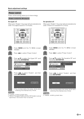
... button on the Display. • The System enters standby mode and the image on the screen disappears. • Both the STANDBY/ON indicator on the AVC System and the POWER indicator on the Display change from the Setup menu. NOTE • If you are not going to use this System for... button MAIN POWER POWER indicator 1 Press MAIN POWER on the Display. • The POWER indicator on the Display flashes red. 2 Press MAIN POWER on the AVC System. • The System turns the power on. • The POWER indicator on the Display lights up green and the STANDBY/ON indicator on the...
... button on the Display. • The System enters standby mode and the image on the screen disappears. • Both the STANDBY/ON indicator on the AVC System and the POWER indicator on the Display change from the Setup menu. NOTE • If you are not going to use this System for... button MAIN POWER POWER indicator 1 Press MAIN POWER on the Display. • The POWER indicator on the Display flashes red. 2 Press MAIN POWER on the AVC System. • The System turns the power on. • The POWER indicator on the Display lights up green and the STANDBY/ON indicator on the...
LC-37HV6U Operation Manual
Page 23
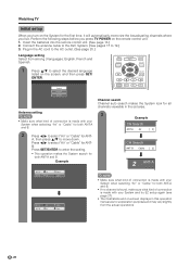
... TV POWER on the remote control unit. 1. A, then press a/b to 19.) 3. Press c/d to select "Air" or "Cable" for ANT- B. Connect the antenna cable to the AVC System. (See pages 17 to move down. Plug in this operation manual are for both ANT-A and B. • If no channel is found, make sure...
... TV POWER on the remote control unit. 1. A, then press a/b to 19.) 3. Press c/d to select "Air" or "Cable" for ANT- B. Connect the antenna cable to the AVC System. (See pages 17 to move down. Plug in this operation manual are for both ANT-A and B. • If no channel is found, make sure...
LC-37HV6U Operation Manual
Page 40
... you to select "No Signal Off", and then press SET/ENTER. NOTE • "Disable" is factory preset value. • When a TV program finishes, and the AVC System receives signal input, this function may not operate. • Five minutes before the power shuts down , remaining time displays every minute. TV MENU [Power...
... you to select "No Signal Off", and then press SET/ENTER. NOTE • "Disable" is factory preset value. • When a TV program finishes, and the AVC System receives signal input, this function may not operate. • Five minutes before the power shuts down , remaining time displays every minute. TV MENU [Power...

LC-37HV6U Operation Manual
Page 42
...game console and camcorder. DVD player Digital TV tuner S-VIDEO AV Y/PB/PR S-VIDEO Y/PB/PR AV DVI AVC System (rear view) S-VIDEO AV VCR AV S-VIDEO AV Receiver (Built-in Tuner Amp) AVC System (front view) PC-AUDIO AV PC ANALOG RGB S-VIDEO Game console/ Camcorder CAUTION • To protect... all equipment, always turn off the AVC System before making connections. 41 To view external source images, select the input source from INPUT on the remote control unit or on the ...
...game console and camcorder. DVD player Digital TV tuner S-VIDEO AV Y/PB/PR S-VIDEO Y/PB/PR AV DVI AVC System (rear view) S-VIDEO AV VCR AV S-VIDEO AV Receiver (Built-in Tuner Amp) AVC System (front view) PC-AUDIO AV PC ANALOG RGB S-VIDEO Game console/ Camcorder CAUTION • To protect... all equipment, always turn off the AVC System before making connections. 41 To view external source images, select the input source from INPUT on the remote control unit or on the ...

LC-37HV6U Operation Manual
Page 43
... button Displaying a DVD image 1 To watch a DVD image, select "INPUT1" from "INPUT SOURCE" menu using component video cable, select "COMPONENT" for the signal type. 42 AVC System (rear view) Component video cable (commercially available) When using INPUT on the remote control unit or on the Display. (See page 52.) INPUT SOURCE...
... button Displaying a DVD image 1 To watch a DVD image, select "INPUT1" from "INPUT SOURCE" menu using component video cable, select "COMPONENT" for the signal type. 42 AVC System (rear view) Component video cable (commercially available) When using INPUT on the remote control unit or on the Display. (See page 52.) INPUT SOURCE...

LC-37HV6U Operation Manual
Page 44
NOTE • The S-video terminal has priority over the video terminals. AVC System (rear view) TV POWER TV CBL VCR DVD /SAT /LD /DTV ANT-A/B INPUT AV Virtual MODE MTS CC VIEW MODE TWIN PICTURE FREEZE SELECT ...
NOTE • The S-video terminal has priority over the video terminals. AVC System (rear view) TV POWER TV CBL VCR DVD /SAT /LD /DTV ANT-A/B INPUT AV Virtual MODE MTS CC VIEW MODE TWIN PICTURE FREEZE SELECT ...
LC-37HV6U Operation Manual
Page 45
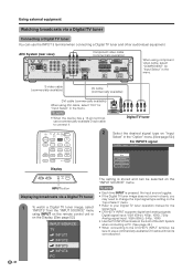
... VGA (60Hz), 480p, 1080i, 720p Analog signal input: VGA (60Hz), 540p, 1080i • Use the PC INPUT terminals on the front of the AVC System when connecting a PC. (See page 46.) • When connecting to the DVI-HDTV INPUT terminal, be selected on the "INPUT SOURCE" menu.... button Displaying broadcasts via a Digital TV tuner Connecting a Digital TV tuner You can be sure to use a commercially available D-sub cable to connect it. AVC System (rear view) Component video cable (commercially available) When using DVI cable, select "DVI" for "Input Select" in the "Option" menu. (See...
... VGA (60Hz), 480p, 1080i, 720p Analog signal input: VGA (60Hz), 540p, 1080i • Use the PC INPUT terminals on the front of the AVC System when connecting a PC. (See page 46.) • When connecting to the DVI-HDTV INPUT terminal, be selected on the "INPUT SOURCE" menu.... button Displaying broadcasts via a Digital TV tuner Connecting a Digital TV tuner You can be sure to use a commercially available D-sub cable to connect it. AVC System (rear view) Component video cable (commercially available) When using DVI cable, select "DVI" for "Input Select" in the "Option" menu. (See...

LC-37HV6U Operation Manual
Page 46
NOTE • Each time INPUT is pressed, the input source toggles. 45 AVC System (front view) AV cable (commercially available) S-video cable (commercially available) TV POWER TV CBL VCR DVD /SAT /LD /DTV ANT-A/B INPUT AV Virtual MODE ...
NOTE • Each time INPUT is pressed, the input source toggles. 45 AVC System (front view) AV cable (commercially available) S-video cable (commercially available) TV POWER TV CBL VCR DVD /SAT /LD /DTV ANT-A/B INPUT AV Virtual MODE ...

LC-37HV6U Operation Manual
Page 47
... with the System. INPUT SOURCE TV INPUT1 INPUT2 INPUT3 INPUT4 PC You only need to select the input source on the "INPUT 46 SOURCE" menu. AVC System (front view) RGB cable (commercially available) PC ø 3.5 mm stereo minijack cable (commercially available) Signal names for 15-pin mini D-sub connecter 543 21...
... with the System. INPUT SOURCE TV INPUT1 INPUT2 INPUT3 INPUT4 PC You only need to select the input source on the "INPUT 46 SOURCE" menu. AVC System (front view) RGB cable (commercially available) PC ø 3.5 mm stereo minijack cable (commercially available) Signal names for 15-pin mini D-sub connecter 543 21...

LC-37HV6U Operation Manual
Page 52
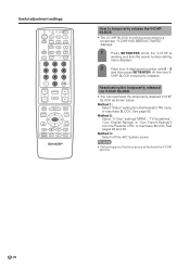
... you can easily adjust the picture as necessary to change the PC image and try again. • Be sure to connect the PC to the AVC System and switch it to optimize the image. If not successful, change image position using Auto Sync. Selected item Description H-Pos. Fine Sync. MENU RETURN...
... you can easily adjust the picture as necessary to change the PC image and try again. • Be sure to connect the PC to the AVC System and switch it to optimize the image. If not successful, change image position using Auto Sync. Selected item Description H-Pos. Fine Sync. MENU RETURN...
LC-37HV6U Operation Manual
Page 67
... menu to reactivate BLOCK. NOTE • Performing any of the three above will activate the V-CHIP BLOCK. 66 At this time V- Method 3: Switch off the AVC System power. Useful adjustment settings TV POWER TV CBL VCR DVD /SAT /LD /DTV ANT-A/B INPUT AV Virtual MODE MTS CC VIEW MODE TWIN PICTURE...
... menu to reactivate BLOCK. NOTE • Performing any of the three above will activate the V-CHIP BLOCK. 66 At this time V- Method 3: Switch off the AVC System power. Useful adjustment settings TV POWER TV CBL VCR DVD /SAT /LD /DTV ANT-A/B INPUT AV Virtual MODE MTS CC VIEW MODE TWIN PICTURE...

LC-37HV6U Operation Manual
Page 77
... off . • Is the sleep timer set correctly? Appendix Troubleshooting Problem • No power Possible Solution • Make sure the Display and the AVC System are connected correctly. (See page 9.) • Check if you pressed TV POWER on the remote control unit. (See page 21.) If the .... • Is the AC cord disconnected? (See page 20.) • Has the main power been turned on the power of the Display and the AVC System, or unplugging the AC cord and replugging it under strong or fluorescent lighting? • Is a fluorescent light illuminated near a heater, as lightning,...
... off . • Is the sleep timer set correctly? Appendix Troubleshooting Problem • No power Possible Solution • Make sure the Display and the AVC System are connected correctly. (See page 9.) • Check if you pressed TV POWER on the remote control unit. (See page 21.) If the .... • Is the AC cord disconnected? (See page 20.) • Has the main power been turned on the power of the Display and the AVC System, or unplugging the AC cord and replugging it under strong or fluorescent lighting? • Is a fluorescent light illuminated near a heater, as lightning,...


