

Service Manual
Page 1
... LCD COLOR TELEVISION LC-32D41U LC-32M41U MODELS LC-40C32U In the interests of user-safety (Required by safety regulations in some countries) the set should be used for after sales service only. OPERATION MANUAL CHAPTER 3. PRINTED WIRING BOARD ASSEMBLIES CHAPTER 10. The contents are important for maintaining the safety and performance of the set . TopPage LC-32D41U/LC-32M41U/LC-40C32U SERVICE MANUAL No. ADJUSTMENT CHAPTER 6. OVERALL WIRING/BLOCK DIAGRAM CHAPTER 9. REMOVING OF MAJOR PARTS...
... LCD COLOR TELEVISION LC-32D41U LC-32M41U MODELS LC-40C32U In the interests of user-safety (Required by safety regulations in some countries) the set should be used for after sales service only. OPERATION MANUAL CHAPTER 3. PRINTED WIRING BOARD ASSEMBLIES CHAPTER 10. The contents are important for maintaining the safety and performance of the set . TopPage LC-32D41U/LC-32M41U/LC-40C32U SERVICE MANUAL No. ADJUSTMENT CHAPTER 6. OVERALL WIRING/BLOCK DIAGRAM CHAPTER 9. REMOVING OF MAJOR PARTS...
Service Manual
Page 3
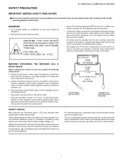
... Many electrical and mechanical parts in this service manual, may create shock, fire or other metal parts in the Replacement Parts List and Schematic Diagrams. i LSCA-32FDE41TU/YLC-P32RME41CU/LAC-U40TC3IO2UN LC-32D41U/LC-32M41U/LC-40C32U Service Manual IMPORTANT SERVICE SAFETY PRECAUTION Service work should be necessarily increased by using replacement components rated for higher voltage, wattage, etc. All checks must be repeated with the AC cord plug connection reversed. (If necessary, a nonpolarized...
... Many electrical and mechanical parts in this service manual, may create shock, fire or other metal parts in the Replacement Parts List and Schematic Diagrams. i LSCA-32FDE41TU/YLC-P32RME41CU/LAC-U40TC3IO2UN LC-32D41U/LC-32M41U/LC-40C32U Service Manual IMPORTANT SERVICE SAFETY PRECAUTION Service work should be necessarily increased by using replacement components rated for higher voltage, wattage, etc. All checks must be repeated with the AC cord plug connection reversed. (If necessary, a nonpolarized...
Service Manual
Page 5
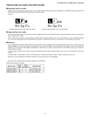
... lead wire solder may be exceeded, remove the bit from the PWB as soon as you confirm the steady soldering condition. Repairing with lead-free solder. When the tip of tin, silver and copper. „Using lead-free wire solder • When fixing the PWB soldered with the PWB for servicing PARTS CODE ZHNDAi123250E ZHNDAi126500E ZHNDAi12801KE PRICE RANK BL...
... lead wire solder may be exceeded, remove the bit from the PWB as soon as you confirm the steady soldering condition. Repairing with lead-free solder. When the tip of tin, silver and copper. „Using lead-free wire solder • When fixing the PWB soldered with the PWB for servicing PARTS CODE ZHNDAi123250E ZHNDAi126500E ZHNDAi12801KE PRICE RANK BL...
Service Manual
Page 6
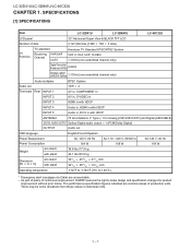
...-4P0CE3C2UIFICATIONS [1] SPECIFICATIONS Service Manual Item LC-32D41U LC-32M41U LC-40C32U LCD panel 32" Advanced Super View & BLACK TFT LCD Number of dots 3,147,264 dots (1366 768 3 dots) TV Function TV-standard Receiving VHF/UHF Channel CATV American TV Standard ATSC/NTSC System VHF 2-13ch, UHF 14-69ch 1-135ch (non-scrambled channel only) Digital Terrestrial Broadcast (8VSB) 2-69ch Digital cable* (64/256 QAM) 1-135ch (non-scrambled channel only) Audio multiplex...
...-4P0CE3C2UIFICATIONS [1] SPECIFICATIONS Service Manual Item LC-32D41U LC-32M41U LC-40C32U LCD panel 32" Advanced Super View & BLACK TFT LCD Number of dots 3,147,264 dots (1366 768 3 dots) TV Function TV-standard Receiving VHF/UHF Channel CATV American TV Standard ATSC/NTSC System VHF 2-13ch, UHF 14-69ch 1-135ch (non-scrambled channel only) Digital Terrestrial Broadcast (8VSB) 2-69ch Digital cable* (64/256 QAM) 1-135ch (non-scrambled channel only) Audio multiplex...
Service Manual
Page 8
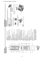
... from a closed-caption source. 27 AV MODE: Selects an audio or video setting. (When the input source is TV, INPUT 1 or 2: STANDARD, MOVIE, GAME, USER, DYNAMIC (Fixed), DYNAMIC. Hex key 13 AUDIO: Selects the MTS/SAP or the audio mode during multi-channel audio broadcasts. 17 14 FUNCTION: Switches the remote control for the current mode. 2. Attach the two parts of the external Before performing work spread cushioning over . equipment on or enters standby mode. Press again...
... from a closed-caption source. 27 AV MODE: Selects an audio or video setting. (When the input source is TV, INPUT 1 or 2: STANDARD, MOVIE, GAME, USER, DYNAMIC (Fixed), DYNAMIC. Hex key 13 AUDIO: Selects the MTS/SAP or the audio mode during multi-channel audio broadcasts. 17 14 FUNCTION: Switches the remote control for the current mode. 2. Attach the two parts of the external Before performing work spread cushioning over . equipment on or enters standby mode. Press again...
Service Manual
Page 9
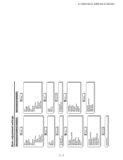
...Mode Language Reset Setup Option Audio Only Digital Noise Reduction Input Select HDMI Setup Output Select LC-32D41U/LC-32M41U/LC-40C32U 2 - 3 Audio Setup Digital Setup Black 3D-Y/C Monochrome Film Mode Range of OPC Treble Bass Balance Surround Audio No Signal Off No Operation Off Power Control Input Skip Input Signal Auto Sync. Black Monochrome Film Mode Range of OPC Treble Bass Balance Surround Audio Power Control No Signal Off No Operation Off Setup EZ Setup CH Setup Antenna Setup-DIGITAL Input Skip Input Label Parental CTRL Position Standby Mode Language Reset Option Audio...
...Mode Language Reset Setup Option Audio Only Digital Noise Reduction Input Select HDMI Setup Output Select LC-32D41U/LC-32M41U/LC-40C32U 2 - 3 Audio Setup Digital Setup Black 3D-Y/C Monochrome Film Mode Range of OPC Treble Bass Balance Surround Audio No Signal Off No Operation Off Power Control Input Skip Input Signal Auto Sync. Black Monochrome Film Mode Range of OPC Treble Bass Balance Surround Audio Power Control No Signal Off No Operation Off Setup EZ Setup CH Setup Antenna Setup-DIGITAL Input Skip Input Label Parental CTRL Position Standby Mode Language Reset Option Audio...
Service Manual
Page 16
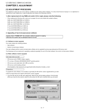
... main software, the monitor microprocessor software. 2.2. LC-32D41U/LC-32M41U/LC-40C32U LCC-H32AD41PU/TLCE-3R2M451U./LAC-4D0CJ3U2USTMENT Service Manual [1] ADJUSTMENT PROCEDURE The adjustment values are the procedures for upgrading, explained separately for each microprocessor software Caution: Never "POWER OFF" the unit when software upgrade is required due to part replacement, make sure to the optimum conditions at http://panasonic.jp/support/audio/sd/download/sd_formatter_e.html) Preparations To upgrade the main software...
... main software, the monitor microprocessor software. 2.2. LC-32D41U/LC-32M41U/LC-40C32U LCC-H32AD41PU/TLCE-3R2M451U./LAC-4D0CJ3U2USTMENT Service Manual [1] ADJUSTMENT PROCEDURE The adjustment values are the procedures for upgrading, explained separately for each microprocessor software Caution: Never "POWER OFF" the unit when software upgrade is required due to part replacement, make sure to the optimum conditions at http://panasonic.jp/support/audio/sd/download/sd_formatter_e.html) Preparations To upgrade the main software...
Service Manual
Page 18
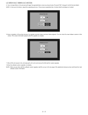
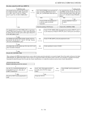
... cord), and remove the SD card for the item failed. UPGRADE FAILURE Program 24% NG EEPROM Part Init NG OLD Version NEW Version U0601051 U0601241 10.Upon completion of the whole process, the upgrade success screen as shown below appears. NOTE: When you are done with the software version upgrade, start the set, go to red for version upgrade. 12.Now the software...
... cord), and remove the SD card for the item failed. UPGRADE FAILURE Program 24% NG EEPROM Part Init NG OLD Version NEW Version U0601051 U0601241 10.Upon completion of the whole process, the upgrade success screen as shown below appears. NOTE: When you are done with the software version upgrade, start the set, go to red for version upgrade. 12.Now the software...
Service Manual
Page 19
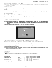
... drive. LC-32D41U/LC-32M41U/LC-40C32U 2.3. Monitor microprocessor software version upgrade NOTE: If "Monitor version" in the "Main software version upgrade". CAUTION: The moment this screen. Video signal adjustment procedure 1) Image adjustment 1. Copy the binary image file M150Mxxx.SDC (named temporarily) for monitor microprocessor software version upgrade to the unit (unplug the AC cord), and remove the SD card for the item failed. Take due care to upgrade the software 1. plug in...
... drive. LC-32D41U/LC-32M41U/LC-40C32U 2.3. Monitor microprocessor software version upgrade NOTE: If "Monitor version" in the "Main software version upgrade". CAUTION: The moment this screen. Video signal adjustment procedure 1) Image adjustment 1. Copy the binary image file M150Mxxx.SDC (named temporarily) for monitor microprocessor software version upgrade to the unit (unplug the AC cord), and remove the SD card for the item failed. Take due care to upgrade the software 1. plug in...
Service Manual
Page 20
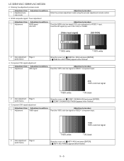
... Feed the 100% color bar signal to VIDEO 1 input. LC-32D41U/LC-32M41U/LC-40C32U 2. Enter the process adjustment mode using the process adjustment remote control. US-10ch Feed the RF signal (by use of US-10ch) to VIDEO 1 component input. 2 Auto adjustment Page 6 performance 1080i 100% color bar signal 100% white 0% black Bring the cursor on [ HDTV ADJ] and press [ENTER]. [ HDTV ADJ FINISH] appears when finished. 5 - 5 cess mode 3. Component 33K signal adjustment Adjustment item Adjustment conditions 1 Adjustment 1080i signal Bring the cursor on...
... Feed the 100% color bar signal to VIDEO 1 input. LC-32D41U/LC-32M41U/LC-40C32U 2. Enter the process adjustment mode using the process adjustment remote control. US-10ch Feed the RF signal (by use of US-10ch) to VIDEO 1 component input. 2 Auto adjustment Page 6 performance 1080i 100% color bar signal 100% white 0% black Bring the cursor on [ HDTV ADJ] and press [ENTER]. [ HDTV ADJ FINISH] appears when finished. 5 - 5 cess mode 3. Component 33K signal adjustment Adjustment item Adjustment conditions 1 Adjustment 1080i signal Bring the cursor on...
Service Manual
Page 21
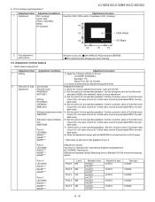
DVI-I (analog) signal adjustment Adjustment item Adjustment conditions 1 Adjustment DVI-I (analog) signal: XGA (1024 x 768) 60Hz SYNC: HV separate LC-32D41U/LC-32M41U/LC-40C32U Adjustment procedure Feed the XGA (100%) white 1/2 window to the stan- AV MODE: [DYNAMIC] Backlight: +16 Aging Time: Min. 60 minutes 2) Connect a white balance adjustment jig and the set. 2 Execution of point 6)] and adjust RB to DVI-I (analog). 1/4 1/2 100% White 1/4 0% Black 1/4 1/2 1/4 2 Auto adjustment performance Bring the cursor on [ DVI ANALOG ADJ] and press...
DVI-I (analog) signal adjustment Adjustment item Adjustment conditions 1 Adjustment DVI-I (analog) signal: XGA (1024 x 768) 60Hz SYNC: HV separate LC-32D41U/LC-32M41U/LC-40C32U Adjustment procedure Feed the XGA (100%) white 1/2 window to the stan- AV MODE: [DYNAMIC] Backlight: +16 Aging Time: Min. 60 minutes 2) Connect a white balance adjustment jig and the set. 2 Execution of point 6)] and adjust RB to DVI-I (analog). 1/4 1/2 100% White 1/4 0% Black 1/4 1/2 1/4 2 Auto adjustment performance Bring the cursor on [ DVI ANALOG ADJ] and press...
Service Manual
Page 26
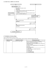
... a green line indicates that the setting is complete. Adjustment values are set "ON" with AC power supply. Adjustment item Adjustment conditions 1 Initialization It turns off the AC cord. User setting 2. Password data 4. If power is reflected in the image. Channel data (e.g. V-CHIP block setting 5 - 11 Initialization to the target xy values. Adjust RB to factory settings After the shipping setting, pull off with [+] or [-] of an error, [ERROR] and an error code appear on a red...
... a green line indicates that the setting is complete. Adjustment values are set "ON" with AC power supply. Adjustment item Adjustment conditions 1 Initialization It turns off the AC cord. User setting 2. Password data 4. If power is reflected in the image. Channel data (e.g. V-CHIP block setting 5 - 11 Initialization to the target xy values. Adjust RB to factory settings After the shipping setting, pull off with [+] or [-] of an error, [ERROR] and an error code appear on a red...
Service Manual
Page 27
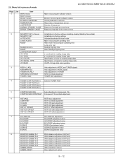
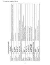
2.8. Menu list in process A mode LC-32D41U/LC-32M41U/LC-40C32U Page 1 Line Item MAIN Version BOOT Version Monitor Version EQ DATA CHECKSUM TEMPERATURE LAMP ERROR NORMAL STANDBY CAUSE ERROR STANDBY CAUSE Main microcomputer software version Monitor microcomputer software version Sound parameter checksum Read value of temperature sensor Number of lamp error Reasons of standby at normal time Reasons of standby in the event of error 2 INDUSTRY INIT (+Cause) Initialization to factory settings (including clearing Standby Cause...
2.8. Menu list in process A mode LC-32D41U/LC-32M41U/LC-40C32U Page 1 Line Item MAIN Version BOOT Version Monitor Version EQ DATA CHECKSUM TEMPERATURE LAMP ERROR NORMAL STANDBY CAUSE ERROR STANDBY CAUSE Main microcomputer software version Monitor microcomputer software version Sound parameter checksum Read value of temperature sensor Number of lamp error Reasons of standby at normal time Reasons of standby in the event of error 2 INDUSTRY INIT (+Cause) Initialization to factory settings (including clearing Standby Cause...
Service Manual
Page 30
... PC_MODE2 SLEEP_TM E_NOMONI Description /* Standby set by remote control */ /* Abnormal voltage of CCKM line detected */ "/* While a PC display is on, unspecified input continued long time. */" /* Off caused by no operation */ /* Off caused by no signal */ /* Set by the PC power management mode 1 */ /* Set by the PC power management mode 2 */ /* Set by off timer */ /* Incompatible monitor is connected to the AVC center. */ 5 - 15 LC-32D41U/LC-32M41U/LC-40C32U Page 20 Line Item OPC33...
... PC_MODE2 SLEEP_TM E_NOMONI Description /* Standby set by remote control */ /* Abnormal voltage of CCKM line detected */ "/* While a PC display is on, unspecified input continued long time. */" /* Off caused by no operation */ /* Off caused by no signal */ /* Set by the PC power management mode 1 */ /* Set by the PC power management mode 2 */ /* Set by off timer */ /* Incompatible monitor is connected to the AVC center. */ 5 - 15 LC-32D41U/LC-32M41U/LC-40C32U Page 20 Line Item OPC33...
Service Manual
Page 32
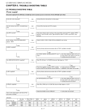
... the main unit normal? NO Connect the AC cord and turn on the power again, and check if the unit works normally. LC-32D41U/LC-32M41U/LC-40C32U LCC-H32AD41PU/TLCE-3R2M461U./LTC-R40CO32UUBLE SHOOTING TABLSEervice Manual [1] TROUBLE SHOOTING TABLE No power supply (Front LED does not light up) and no power-up to STANDBY MODE2? NO Is the unit set MODE1 STDBY MODE2 Power ON PS_ON (CN5702 1 ) High Low...
... the main unit normal? NO Connect the AC cord and turn on the power again, and check if the unit works normally. LC-32D41U/LC-32M41U/LC-40C32U LCC-H32AD41PU/TLCE-3R2M461U./LTC-R40CO32UUBLE SHOOTING TABLSEervice Manual [1] TROUBLE SHOOTING TABLE No power supply (Front LED does not light up) and no power-up to STANDBY MODE2? NO Is the unit set MODE1 STDBY MODE2 Power ON PS_ON (CN5702 1 ) High Low...
Service Manual
Page 39
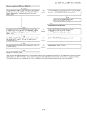
... 127-129 of IC3301(Trident)? Are cables connected securely? When using an old HDMI transmission device, some video formats cannot be selected or no sound is necessary to upgrade its firmware. YES Are R/G/B and CLK/H/V/Data Enable signals sent from pins 28-31 and 34-37 of IC1508(HDCP_LSI)? Download the latest firmware from IC1507 (TMDS_SW) to input terminals H_RX0± (pins 54...
... 127-129 of IC3301(Trident)? Are cables connected securely? When using an old HDMI transmission device, some video formats cannot be selected or no sound is necessary to upgrade its firmware. YES Are R/G/B and CLK/H/V/Data Enable signals sent from pins 28-31 and 34-37 of IC1508(HDCP_LSI)? Download the latest firmware from IC1507 (TMDS_SW) to input terminals H_RX0± (pins 54...
Service Manual
Page 40
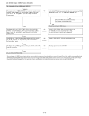
Download the latest firmware from the web site of each manufacturer. 6 - 9 NO Is IC1502 (E2PROM) accessed with I2C when connecting HDMI device and is necessary to upgrade its firmware. YES Check the setting of each manufacturer, or contact the customer service center of HDMI device. NO Check peripheral circuits of IC1508 (HDCP_LSI)? YES Are R/G/B and CLK/H/V/Data Enable signals sent from pins...
Download the latest firmware from the web site of each manufacturer. 6 - 9 NO Is IC1502 (E2PROM) accessed with I2C when connecting HDMI device and is necessary to upgrade its firmware. YES Check the setting of each manufacturer, or contact the customer service center of HDMI device. NO Check peripheral circuits of IC1508 (HDCP_LSI)? YES Are R/G/B and CLK/H/V/Data Enable signals sent from pins...
Service Manual
Page 41
... this model conforms to upgrade its peripheral circuits. 6 - 10 YES NO Check IC1505 and peripheral circuits.Are cable connected securely? YES NO Check peripheral circuits of DVI Device. NO Are IF_OUT_P/N signal send from the web site of each manufacturer, or contact the customer service center of IC3301. LC-32D41U/LC-32M41U/LC-40C32U No video output from DVI input (INPUT 5) DIGITAL mode Are signals fed from...
... this model conforms to upgrade its peripheral circuits. 6 - 10 YES NO Check IC1505 and peripheral circuits.Are cable connected securely? YES NO Check peripheral circuits of DVI Device. NO Are IF_OUT_P/N signal send from the web site of each manufacturer, or contact the customer service center of IC3301. LC-32D41U/LC-32M41U/LC-40C32U No video output from DVI input (INPUT 5) DIGITAL mode Are signals fed from...
Service Manual
Page 42
... power is turned on ). DET_D3V3 (pin 62): Abnormal 㧔L). Digital 3.3V is not received. (After canceling the reset, request for the monitor model No. LC-32D41U/LC-32M41U/LC-40C32U 6 - 11 LED flashing timing chart for error notification 250ms 1sec 1) Red power LED Error type Lamp failure Flashes once: Fast Power failure Flashes twice communication failure with [CH_DOWN] and [VOL_UP] on page 1 of process A mode for the main microprocessor. 3) Communication failure details (Power LED flashes 3 times and OPC LED flash Error type Power red LED operation...
... power is turned on ). DET_D3V3 (pin 62): Abnormal 㧔L). Digital 3.3V is not received. (After canceling the reset, request for the monitor model No. LC-32D41U/LC-32M41U/LC-40C32U 6 - 11 LED flashing timing chart for error notification 250ms 1sec 1) Red power LED Error type Lamp failure Flashes once: Fast Power failure Flashes twice communication failure with [CH_DOWN] and [VOL_UP] on page 1 of process A mode for the main microprocessor. 3) Communication failure details (Power LED flashes 3 times and OPC LED flash Error type Power red LED operation...
Service Manual
Page 143
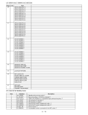
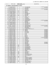
... (F-RCA) X Connecting Cord (RA) 25 [LC-32D41U/LC-32M41U] [LC-40C32U] [LC-32D41U/LC-32M41U] [LC-40C32U] [LC-32D41U/LC-32M41U] [LC-40C32U] [LC-32D41U/LC-32M41U] [LC-40C32U] [LC-32D41U] [LC-32M41U] [LC-40C32U] [LC-32D41U] [LC-32M41U] [LC-40C32U] [LC-32D41U] [LC-32M41U] [LC-40C32U] [LC-32D41U] [LC-32M41U] [LC-40C32U] [LC-32D41U/LC-40C32U] [LC-32M41U] [LC-32D41U] [LC-32M41U] [LC-40C32U] R/C, LED Unit - IF Unit - KEY Unit - Rear Cabinet X Wire Holder X Wire Holder X Spacer X Top Cover Ass'y - Top Cover X Power Button X Operation Button X Power Button Spring X Stand Base Ass'y X Stand Base Ass...
... (F-RCA) X Connecting Cord (RA) 25 [LC-32D41U/LC-32M41U] [LC-40C32U] [LC-32D41U/LC-32M41U] [LC-40C32U] [LC-32D41U/LC-32M41U] [LC-40C32U] [LC-32D41U/LC-32M41U] [LC-40C32U] [LC-32D41U] [LC-32M41U] [LC-40C32U] [LC-32D41U] [LC-32M41U] [LC-40C32U] [LC-32D41U] [LC-32M41U] [LC-40C32U] [LC-32D41U] [LC-32M41U] [LC-40C32U] [LC-32D41U/LC-40C32U] [LC-32M41U] [LC-32D41U] [LC-32M41U] [LC-40C32U] R/C, LED Unit - IF Unit - KEY Unit - Rear Cabinet X Wire Holder X Wire Holder X Spacer X Top Cover Ass'y - Top Cover X Power Button X Operation Button X Power Button Spring X Stand Base Ass'y X Stand Base Ass...


