
Service Manual
Page 2
... 8-3 [9] G: MOTOR SWITCH TEST 8-3 [10] H: BLOWN MINITOR FUSE TEST 8-4 [11] I: NOISE FILTER TEST 8-4 [12] J: TOUCH CONTROL PANEL ASSEMBLY TEST 8-4 [13] K: KEY UNIT TEST 8-5 [14] L: RELAY TEST 8-6 [15] M: DEFROST TEST 8-6 [16] N: FOIL PATTERN ON THE PRINTED WIRING BOARD TEST 8-6 CHAPTER 9.
... 8-3 [9] G: MOTOR SWITCH TEST 8-3 [10] H: BLOWN MINITOR FUSE TEST 8-4 [11] I: NOISE FILTER TEST 8-4 [12] J: TOUCH CONTROL PANEL ASSEMBLY TEST 8-4 [13] K: KEY UNIT TEST 8-5 [14] L: RELAY TEST 8-6 [15] M: DEFROST TEST 8-6 [16] N: FOIL PATTERN ON THE PRINTED WIRING BOARD TEST 8-6 CHAPTER 9.
Service Manual
Page 8
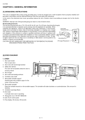
... 6 12 securely closed. 4. Electrical Requirements The electrical requirements are a 115 -120 volt 60 Hz, AC only, 15 or 20 amp. Door hinges 1 5. Turntable motor shaft 3 2 11 10 3 7 7. WARNING: Improper use of the grounding plug can be... a 3-wire, 15 amp. Do not drape over a countertop or table where it should be pulled on the turntable support. Removable turntable...2. When installing this appliance be provided. Time display: 99 minutes, 99 seconds 5 - 1 R-231NW CHAPTER 5.
... 6 12 securely closed. 4. Electrical Requirements The electrical requirements are a 115 -120 volt 60 Hz, AC only, 15 or 20 amp. Door hinges 1 5. Turntable motor shaft 3 2 11 10 3 7 7. WARNING: Improper use of the grounding plug can be... a 3-wire, 15 amp. Do not drape over a countertop or table where it should be pulled on the turntable support. Removable turntable...2. When installing this appliance be provided. Time display: 99 minutes, 99 seconds 5 - 1 R-231NW CHAPTER 5.
Service Manual
Page 17
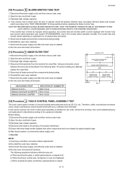
...SWITCH, DOOR SENSING SWITCH AND MONITOR SWITCH FOR PROPER OPERATION. Reconnect the power supply cord after the outer case is comprised of a 15 ampere fuse and switch. 5. Discharge high voltage capacitor. 4. Disconnect the lead wires from components during testing. 6. If incorrect reading ... the outer case (cabinet). 7. Disconnect the power supply cord, and then remove outer case. 2. Reinstall the outer case (cabinet). 7. R-231NW [10] Procedure H : BLOWN MINITOR FUSE TEST 1. Reconnect all leads removed from the terminal the noise filter. Disconnect the power supply...
...SWITCH, DOOR SENSING SWITCH AND MONITOR SWITCH FOR PROPER OPERATION. Reconnect the power supply cord after the outer case is comprised of a 15 ampere fuse and switch. 5. Discharge high voltage capacitor. 4. Disconnect the lead wires from components during testing. 6. If incorrect reading ... the outer case (cabinet). 7. Disconnect the power supply cord, and then remove outer case. 2. Reinstall the outer case (cabinet). 7. R-231NW [10] Procedure H : BLOWN MINITOR FUSE TEST 1. Reconnect all leads removed from the terminal the noise filter. Disconnect the power supply...
Service Manual
Page 19
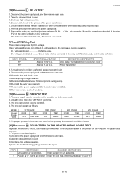
...cord and then remove outer case. 10.Open the door and block it open . 11.Discharge high voltage capacitor. 12.Reconnect all functions. [15] Procedure M : DEFROST TEST 1. Place one cup of water in Defrost cooking condition. 4. MENU Steaks/ Chops 0.5lb 1ST STAGE LEVEL ... 11.2V D.C. STEPS OCCURRENCE CAUSE OR CORRECTION 1 Only pattern at "a" is probably defective and should indicate 120 volts, if not check oven circuit. R-231NW [14] Procedure L : RELAY TEST 1. voltage Check voltage at "a" and "b" are operated by using insulation tape. 6. RELAY SYMBOL RY1 RY2 OPERATIONAL ...
...cord and then remove outer case. 10.Open the door and block it open . 11.Discharge high voltage capacitor. 12.Reconnect all functions. [15] Procedure M : DEFROST TEST 1. Place one cup of water in Defrost cooking condition. 4. MENU Steaks/ Chops 0.5lb 1ST STAGE LEVEL ... 11.2V D.C. STEPS OCCURRENCE CAUSE OR CORRECTION 1 Only pattern at "a" is probably defective and should indicate 120 volts, if not check oven circuit. R-231NW [14] Procedure L : RELAY TEST 1. voltage Check voltage at "a" and "b" are operated by using insulation tape. 6. RELAY SYMBOL RY1 RY2 OPERATIONAL ...
Service Manual
Page 29
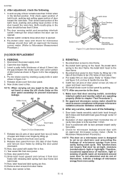
... to the door; 1) Make sure that door sensing switch, secondary interlock switch and monitor switch are free. 15. This function does not require that latch head goes through latch holes and that door be opened . 4. R-231NW 2. Now, door panel is free. 11. Check for microwave leakage around oven door is to Microwave...
... to the door; 1) Make sure that door sensing switch, secondary interlock switch and monitor switch are free. 15. This function does not require that latch head goes through latch holes and that door be opened . 4. R-231NW 2. Now, door panel is free. 11. Check for microwave leakage around oven door is to Microwave...