

Service Manual
Page 1
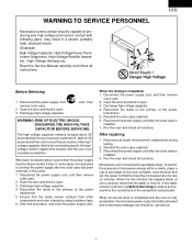
... manual must be used in a severe, possibly fatal, electrical shock. (High Voltage Capacitor, High Voltage Power Transformer, Magnetron, High Voltage Rectifier Assembly, High Voltage Harness etc..) TABLE OF CONTENTS Page PRECAUTIONS TO BE OBSERVED BEFORE AND DURING SERVICING TO AVOID POSSIBLE EXPOSURE TO EXCESSIVE MICROWAVE ENERGY INSIDE FRONT COVER BEFORE SERVICING ...INSIDE FRONT COVER WARNING TO SERVICE PERSONNEL ...1 MICROWAVE MEASUREMENT PROCEDURE 2 FOREWORD AND WARNING ...3 PRODUCT SPECIFICATIONS ...4 GENERAL INFORMATION ...4 PARTS LIST...
... manual must be used in a severe, possibly fatal, electrical shock. (High Voltage Capacitor, High Voltage Power Transformer, Magnetron, High Voltage Rectifier Assembly, High Voltage Harness etc..) TABLE OF CONTENTS Page PRECAUTIONS TO BE OBSERVED BEFORE AND DURING SERVICING TO AVOID POSSIBLE EXPOSURE TO EXCESSIVE MICROWAVE ENERGY INSIDE FRONT COVER BEFORE SERVICING ...INSIDE FRONT COVER WARNING TO SERVICE PERSONNEL ...1 MICROWAVE MEASUREMENT PROCEDURE 2 FOREWORD AND WARNING ...3 PRODUCT SPECIFICATIONS ...4 GENERAL INFORMATION ...4 PARTS LIST...

Service Manual
Page 2
... the user not to operate the oven and 2) contact SHARP ELECTRONICS CORPORATION and Food and Drug Administration's Center for proper alignment, integrity, and connections. (d) Any defective or misadjusted components in the interlock, monitor, door seal, and microwave generation and transmission systems shall be repaired, replaced, or adjusted by procedures described in this service manual. Service personnel should be instructed not to use the unit...
... the user not to operate the oven and 2) contact SHARP ELECTRONICS CORPORATION and Food and Drug Administration's Center for proper alignment, integrity, and connections. (d) Any defective or misadjusted components in the interlock, monitor, door seal, and microwave generation and transmission systems shall be repaired, replaced, or adjusted by procedures described in this service manual. Service personnel should be instructed not to use the unit...
Service Manual
Page 3
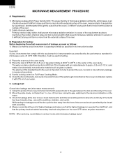
... (cabinet). 6. After repairing 1. When the two minutes has elapsed (timer at zero) carefully check that procedure, reconnect the power supply cord. Open the door and block it open . 3. Ensure that is fully assembled, the microwave power output should be checked and a microwave leakage test should not be operated empty. Run the oven and check all functions. Reconnect all leads removed from other components and oven chassis by using...
... (cabinet). 6. After repairing 1. When the two minutes has elapsed (timer at zero) carefully check that procedure, reconnect the power supply cord. Open the door and block it open . 3. Ensure that is fully assembled, the microwave power output should be checked and a microwave leakage test should not be operated empty. Run the oven and check all functions. Reconnect all leads removed from other components and oven chassis by using...
Service Manual
Page 4
... accurately. 4) Set the cooking control on service invoice and microwave leakage report. 2 NOTE: After servicing, record data on Full Power Cooking Mode. 5) Close the door and select a cook cycle of tap water initially at the door screen, sheet metal seams and other accessible positions where the continuity of cool water. Preparation for leakage at 20±5O C (68OF) in its instruction booklet. C. R-401FK R-401FW MICROWAVE MEASUREMENT...
... accurately. 4) Set the cooking control on service invoice and microwave leakage report. 2 NOTE: After servicing, record data on Full Power Cooking Mode. 5) Close the door and select a cook cycle of tap water initially at the door screen, sheet metal seams and other accessible positions where the continuity of cool water. Preparation for leakage at 20±5O C (68OF) in its instruction booklet. C. R-401FK R-401FW MICROWAVE MEASUREMENT...
Service Manual
Page 5
Check the interlock switches and the door seal carefully. DANGER Certain initial parts are not defective. (C) The door packing is not damaged. (D) The door is not deformed or warped. (E) There is no other visible damage with Operation and Service Information for the SHARP MICROWAVE OVENS, R-401FK and R-401FW. Service personnel - It is quite similar to voltage above 250V. Servicing and repair work must be qualified to render...
Check the interlock switches and the door seal carefully. DANGER Certain initial parts are not defective. (C) The door packing is not damaged. (D) The door is not deformed or warped. (E) There is no other visible damage with Operation and Service Information for the SHARP MICROWAVE OVENS, R-401FK and R-401FW. Service personnel - It is quite similar to voltage above 250V. Servicing and repair work must be qualified to render...
Service Manual
Page 6
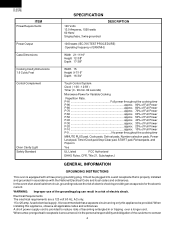
... Power Output Case Dimensions Cooking Cavity Dimensions 1.6 Cubic Feet Control Complement Oven Cavity Light Safety Standard SPECIFICATION 120 Volts 13.0 Amperes, 1550 watts 60 Hertz Single phase, 3 wire grounded DESCRIPTION 1000 watts (IEC 705 TEST PROCEDURE) Operating frequency of 2450MHz Width 21-11/16" Height 12-3/8" Depth 17-3/8" Width 15 Height 9-7/16" Depth 16-3/4" Touch Control System Clock ( 1:00 - 12:59 ) Timer (0 - 99 min. 99 seconds) Microwave Power for the electric...
... Power Output Case Dimensions Cooking Cavity Dimensions 1.6 Cubic Feet Control Complement Oven Cavity Light Safety Standard SPECIFICATION 120 Volts 13.0 Amperes, 1550 watts 60 Hertz Single phase, 3 wire grounded DESCRIPTION 1000 watts (IEC 705 TEST PROCEDURE) Operating frequency of 2450MHz Width 21-11/16" Height 12-3/8" Depth 17-3/8" Width 15 Height 9-7/16" Depth 16-3/4" Touch Control System Clock ( 1:00 - 12:59 ) Timer (0 - 99 min. 99 seconds) Microwave Power for the electric...
Service Manual
Page 7
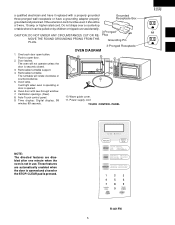
... Receptacle OVEN DIAGRAM 1. Push to open button. Removable turntable support. 4. These features are disabled after one minute when the oven is opened . 6. R-401FW 5 Removable turntable. It will rotate clockwise or counterclockwise. 5. Power supply cord TOUCH CONTROL PANEL R-401FK R-401FW NOTE: The directed features are automatically enabled when the door is not in use. or higher rated cord. One touch door open door. 2. Oven door with a properly grounded three-pronged wall receptacle or have it replaced with see-through window. 7. Ventilation openings. (Rear...
... Receptacle OVEN DIAGRAM 1. Push to open button. Removable turntable support. 4. These features are disabled after one minute when the oven is opened . 6. R-401FW 5 Removable turntable. It will rotate clockwise or counterclockwise. 5. Power supply cord TOUCH CONTROL PANEL R-401FK R-401FW NOTE: The directed features are automatically enabled when the door is not in use. or higher rated cord. One touch door open door. 2. Oven door with a properly grounded three-pronged wall receptacle or have it replaced with see-through window. 7. Ventilation openings. (Rear...

Service Manual
Page 8
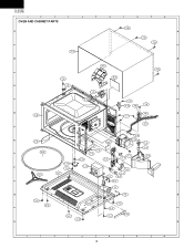
... band Chassis support Latch hook Switch lever Magnetron duct Fan blade Fan duct Oven cavity (Not a replaceable part) Waveguide cover Turntable motor packing Cushion 1 AB 1 AD 1 AF 1 AD 1 AG 1 AC 1 AC 1 -1 AC 1 AA 1 AA 6 NO. DESCRIPTION PART NO. § Q'TY CODE ELECTRIC PARTS 1- 1 1- 2 1- 3 1- 4 1- 5 1- 6 1- 7 1- 8 1- 9 ∆ 1-10 1-11 1-12 1-13 RC-QZA234WRE0 M High voltage capacitor FH-DZB013MRY0 M High voltage rectifier assembly QSOCLB006MRE0 M Oven lamp socket RLMPTA081WRZZ M Oven lamp RMOTEA346WRE0 M Fan motor FFS-BA019/KIT M Monitor switch (V-16G-2C25), C/T fuse (20A 250V...
... band Chassis support Latch hook Switch lever Magnetron duct Fan blade Fan duct Oven cavity (Not a replaceable part) Waveguide cover Turntable motor packing Cushion 1 AB 1 AD 1 AF 1 AD 1 AG 1 AC 1 AC 1 -1 AC 1 AA 1 AA 6 NO. DESCRIPTION PART NO. § Q'TY CODE ELECTRIC PARTS 1- 1 1- 2 1- 3 1- 4 1- 5 1- 6 1- 7 1- 8 1- 9 ∆ 1-10 1-11 1-12 1-13 RC-QZA234WRE0 M High voltage capacitor FH-DZB013MRY0 M High voltage rectifier assembly QSOCLB006MRE0 M Oven lamp socket RLMPTA081WRZZ M Oven lamp RMOTEA346WRE0 M Fan motor FFS-BA019/KIT M Monitor switch (V-16G-2C25), C/T fuse (20A 250V...

Service Manual
Page 9
...7- 7 7- 8 DOOR PARTS FCOV-B202MRK0 M Door frame assembly [R-401FK] FCOV-B203MRK0 M Door frame assembly [R-401FW] LSTPPB021MRF0 M Latch head MSPRTA046WRE0 M Latch spring FDORFB062MRT0 M Door panel PSHEPB021MRE0 M Sealer film HPNL-B087MRE0 M Door screen GCOVHB042MRF0 M Choke cover MISCELLANEOUS FW-VZB125MRE0 M Stop switch harness FW-VZB192MRE0 M Main wire harnes FROLPB025MRK0 M Turntable support NTNT-A108WREZ M Turntable tray TCAUAB045MRR0 M Monitor caution label TCAUAB038MRR0 M DHHS/Screw caution label TINSEB338MRK0 M Operation manual QW-QZB016MRE0 M High voltage wire A SCREWS,NUTS AND WASHERS...
...7- 7 7- 8 DOOR PARTS FCOV-B202MRK0 M Door frame assembly [R-401FK] FCOV-B203MRK0 M Door frame assembly [R-401FW] LSTPPB021MRF0 M Latch head MSPRTA046WRE0 M Latch spring FDORFB062MRT0 M Door panel PSHEPB021MRE0 M Sealer film HPNL-B087MRE0 M Door screen GCOVHB042MRF0 M Choke cover MISCELLANEOUS FW-VZB125MRE0 M Stop switch harness FW-VZB192MRE0 M Main wire harnes FROLPB025MRK0 M Turntable support NTNT-A108WREZ M Turntable tray TCAUAB045MRR0 M Monitor caution label TCAUAB038MRR0 M DHHS/Screw caution label TINSEB338MRK0 M Operation manual QW-QZB016MRE0 M High voltage wire A SCREWS,NUTS AND WASHERS...
Service Manual
Page 10
R-401FK R-401FW 1 2 3 OVEN AND CABINET PARTS A 4 5 6 7-8 A 7-8 7-6 B C D 4-8 2-3 4-7 B 7-6 7-5 6-6 1-9 C 1-5 4-6 7-3 1-13 1-8 7-5 1-6 D 7-7 4-2 7-4 E 4-9 1-10 E 6-5 1-3 7-2 1-4 7-2 6-4 7-4 7-1 4-5 4-10 4-3 1-7 1-11 F 1-12 7-5 1-6 F 2-1 6-3 1-7 7-1 4-4 4-1 1-1 G 1-2 G 7-4 2-2 7-4 2-2 4-11 2-2 7-4 2-2 H H 1 2 3 4 5 6 8
R-401FK R-401FW 1 2 3 OVEN AND CABINET PARTS A 4 5 6 7-8 A 7-8 7-6 B C D 4-8 2-3 4-7 B 7-6 7-5 6-6 1-9 C 1-5 4-6 7-3 1-13 1-8 7-5 1-6 D 7-7 4-2 7-4 E 4-9 1-10 E 6-5 1-3 7-2 1-4 7-2 6-4 7-4 7-1 4-5 4-10 4-3 1-7 1-11 F 1-12 7-5 1-6 F 2-1 6-3 1-7 7-1 4-4 4-1 1-1 G 1-2 G 7-4 2-2 7-4 2-2 4-11 2-2 7-4 2-2 H H 1 2 3 4 5 6 8

Service Manual
Page 11
1 2 3 4 5 CONTROL PANEL PARTS A 3-2-1 3 - 3 3 - 5 3 - 2 3 - 4 3 - 1 3 - 6 B R-401FK R-401FW 6 A B 3-2-3 C 3-2-2 D C DOOR PARTS 5-7 D E F G 5-1 H 1 5-4 5-6 E 5-5 F 5-2 5-3 6-1 G 6-2 6-8 Actual wire harness may be different from illustration. H 2 3 4 5 6 9
1 2 3 4 5 CONTROL PANEL PARTS A 3-2-1 3 - 3 3 - 5 3 - 2 3 - 4 3 - 1 3 - 6 B R-401FK R-401FW 6 A B 3-2-3 C 3-2-2 D C DOOR PARTS 5-7 D E F G 5-1 H 1 5-4 5-6 E 5-5 F 5-2 5-3 6-1 G 6-2 6-8 Actual wire harness may be different from illustration. H 2 3 4 5 6 9
Service Manual
Page 12
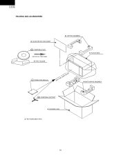
R-401FK R-401FW PACKING AND ACCESSORIES DOOR PROTECTION SHEET 6-5 TURNTABLE TRAY ON TOP OF THE OVEN TRAY HOLDER TOP PAD ASSEMBLY PLASTIC BAG 6-7 OPERATION MANUAL INTO THE OVEN CAVITY BOTTOM PAD ASSEMBLY 6-4 TURNTABLE SUPPORT PACKING CASE Non-replaceable items 10
R-401FK R-401FW PACKING AND ACCESSORIES DOOR PROTECTION SHEET 6-5 TURNTABLE TRAY ON TOP OF THE OVEN TRAY HOLDER TOP PAD ASSEMBLY PLASTIC BAG 6-7 OPERATION MANUAL INTO THE OVEN CAVITY BOTTOM PAD ASSEMBLY 6-4 TURNTABLE SUPPORT PACKING CASE Non-replaceable items 10

Service Manual
Page 16
R-401FK R-401FW COPYRIGHT © 2003 BY SHARP CORPORATION ALL RIGHTS RESERVED. No part of this publication may be reproduced, stored in retrieval systems, or transmitted in any form or by any means, electronic, mechanical, photocopying, recording, or otherwise, without prior written permission of the publisher. 2003 SHARP CORP. (1M2.20E) Printed in U.S.A 14
R-401FK R-401FW COPYRIGHT © 2003 BY SHARP CORPORATION ALL RIGHTS RESERVED. No part of this publication may be reproduced, stored in retrieval systems, or transmitted in any form or by any means, electronic, mechanical, photocopying, recording, or otherwise, without prior written permission of the publisher. 2003 SHARP CORP. (1M2.20E) Printed in U.S.A 14

