
Service Manual
Page 1
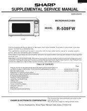
... to those specified should be used . This model is a supplemental Service Manual for after SHARP ELECTRONICS CORPORATION sales service only. Service Headquarters: Sharp Plaza, Mahwah, New Jersey, 07430-2135 The contents are subject to be used for Microwave Oven model R-509FW. R-510FK/FW (S12M182R510FE). This supplemental manual must be used in conjunction with following...
... to those specified should be used . This model is a supplemental Service Manual for after SHARP ELECTRONICS CORPORATION sales service only. Service Headquarters: Sharp Plaza, Mahwah, New Jersey, 07430-2135 The contents are subject to be used for Microwave Oven model R-509FW. R-510FK/FW (S12M182R510FE). This supplemental manual must be used in conjunction with following...
Service Manual
Page 2
...described in excess of any service test or inspection within the microwave generating compartments, check the magnetron, wave guide or transmission line, and cavity for Devices and Radiological Health immediately. R-509FW PRECAUTIONS TO BE OBSERVED BEFORE AND DURING SERVICING TO AVOID ...POSSIBLE EXPOSURE TO EXCESSIVE MICROWAVE ENERGY (a) Do not operate or allow the oven to be operated with the Federal Performance Standard should inform SHARP ELECTRONICS CORPORATION of the specified limit, contact SHARP ELECTRONICS...
...described in excess of any service test or inspection within the microwave generating compartments, check the magnetron, wave guide or transmission line, and cavity for Devices and Radiological Health immediately. R-509FW PRECAUTIONS TO BE OBSERVED BEFORE AND DURING SERVICING TO AVOID ...POSSIBLE EXPOSURE TO EXCESSIVE MICROWAVE ENERGY (a) Do not operate or allow the oven to be operated with the Federal Performance Standard should inform SHARP ELECTRONICS CORPORATION of the specified limit, contact SHARP ELECTRONICS...
Service Manual
Page 3
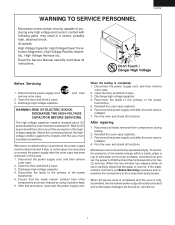
...then remove outer case. 2. After repairing 1. Reconnect the power supply cord after the outer case is installed. 4. R-509FW WARNING TO SERVICE PERSONNEL Microwave ovens contain circuitry capable of producing very high voltage and current, contact with the use of an insulated screwdriver. Disconnect ...cabinet). 3. If the water remains cold carry out Before Servicing procedure and reexamine the connections to HIGH and set the microwave timer for 60 seconds and then short-circuit the connection of the highvoltage capacitor (that procedure, reconnect the power supply cord...
...then remove outer case. 2. After repairing 1. Reconnect the power supply cord after the outer case is installed. 4. R-509FW WARNING TO SERVICE PERSONNEL Microwave ovens contain circuitry capable of producing very high voltage and current, contact with the use of an insulated screwdriver. Disconnect ...cabinet). 3. If the water remains cold carry out Before Servicing procedure and reexamine the connections to HIGH and set the microwave timer for 60 seconds and then short-circuit the connection of the highvoltage capacitor (that procedure, reconnect the power supply cord...
Service Manual
Page 4
... of an electrically nonconductive material such as above mentioned. Secondary interlock relay and door sensing switch shall prevent microwave radiation emission in excess of 5 mW/cm2 at the door screen, sheet metal seams and other accessible ... assembly. 4) Measure carefully at any door movement. Preparation for the maximum indication on service invoice and microwave leakage report. 2 B. Important: Survey instruments that any leakage is important not only to protect the oven... standard load in the center of several minutes. R-509FW MICROWAVE MEASUREMENT PROCEDURE A. C.
... of an electrically nonconductive material such as above mentioned. Secondary interlock relay and door sensing switch shall prevent microwave radiation emission in excess of 5 mW/cm2 at the door screen, sheet metal seams and other accessible ... assembly. 4) Measure carefully at any door movement. Preparation for the maximum indication on service invoice and microwave leakage report. 2 B. Important: Survey instruments that any leakage is important not only to protect the oven... standard load in the center of several minutes. R-509FW MICROWAVE MEASUREMENT PROCEDURE A. C.
Service Manual
Page 5
...(E) There is recommended that service personnel carefully study the entire text of the outer wrap gives access to provide Sharp Electronics Corp. R-509FW SERVICE MANUAL MICROWAVE OVEN R-509FW FOREWORD This Manual has been prepared to voltage above 250V. Service Personnel with the oven. It is no other ...visible damage with Operation and Service Information for the SHARP MICROWAVE OVEN, R-509FW. If provided, Vent Hood, Fan assembly, Cooling Fan Motor. Removal of this manual so that they are used at voltages ...
...(E) There is recommended that service personnel carefully study the entire text of the outer wrap gives access to provide Sharp Electronics Corp. R-509FW SERVICE MANUAL MICROWAVE OVEN R-509FW FOREWORD This Manual has been prepared to voltage above 250V. Service Personnel with the oven. It is no other ...visible damage with Operation and Service Information for the SHARP MICROWAVE OVEN, R-509FW. If provided, Vent Hood, Fan assembly, Cooling Fan Motor. Removal of this manual so that they are used at voltages ...
Service Manual
Page 6
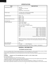
... Rate; fused electrical supply. Where a two-pronged wall-receptacle is encountered, it is equipped with the National Electrical Code and local codes and ordinances. R-509FW ITEM PowerRequirements SPECIFICATION 120 Volts 13.3 Amperes, 1600 watts 60 Hertz Single phase, 3 wire grounded DESCRIPTION Power Output Case Dimensions Cooking Cavity Dimensions 1.8 Cubic ...Width 24" Height 13-3/8" Depth 19-1/8" Width 17-3/8" Height 10-1/2" Depth 18-5/8" Touch Control System Clock ( 1:00 - 12:59 ) Timer (0 - 99 min. 99 seconds) Microwave Power for the electric current. It must be provided.
... Rate; fused electrical supply. Where a two-pronged wall-receptacle is encountered, it is equipped with the National Electrical Code and local codes and ordinances. R-509FW ITEM PowerRequirements SPECIFICATION 120 Volts 13.3 Amperes, 1600 watts 60 Hertz Single phase, 3 wire grounded DESCRIPTION Power Output Case Dimensions Cooking Cavity Dimensions 1.8 Cubic ...Width 24" Height 13-3/8" Depth 19-1/8" Width 17-3/8" Height 10-1/2" Depth 18-5/8" Touch Control System Clock ( 1:00 - 12:59 ) Timer (0 - 99 min. 99 seconds) Microwave Power for the electric current. It must be provided.
Service Manual
Page 8
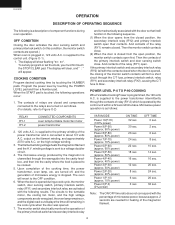
...oven lamp/turntable motor/fan motor power transformer 2. 120 volts A.C. Note: The ON/OFF time ratio does not correspond with the percentage of microwave power, because approx. 2 seconds are activated with the following results. And contacts of the magnetron filament. 6 is supplied to the power ...the START pad is programmed, the 120 volts A.C. output on the high voltage winding. 3. is supplied to a voltage doubler circuit. 4. R-509FW OPERATION DESCRIPTION OF OPERATING SEQUENCE The following is a description of the cooking time, the power transformer, oven lamp, etc.
...oven lamp/turntable motor/fan motor power transformer 2. 120 volts A.C. Note: The ON/OFF time ratio does not correspond with the percentage of microwave power, because approx. 2 seconds are activated with the following results. And contacts of the magnetron filament. 6 is supplied to the power ...the START pad is programmed, the 120 volts A.C. output on the high voltage winding. 3. is supplied to a voltage doubler circuit. 4. R-509FW OPERATION DESCRIPTION OF OPERATING SEQUENCE The following is a description of the cooking time, the power transformer, oven lamp, etc.
Service Manual
Page 10
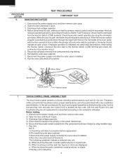
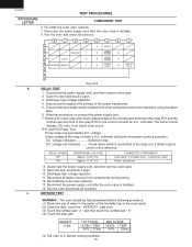
... (cabinet). 7. c) When touching the pads, sometimes a pad produces no signal at all functions. Therefore, unlike conventional microwave ovens, proper maintenance cannot be defective. Reconnect the power supply cord after the outer case is installed. 8. R-509FW PROCEDURE LETTER G MONITOR SWITCH TEST TEST PROCEDURES COMPONENT TEST 1. Before testing, 1) Disconnect the power supply cord, and...
... (cabinet). 7. c) When touching the pads, sometimes a pad produces no signal at all functions. Therefore, unlike conventional microwave ovens, proper maintenance cannot be defective. Reconnect the power supply cord after the outer case is installed. 8. R-509FW PROCEDURE LETTER G MONITOR SWITCH TEST TEST PROCEDURES COMPONENT TEST 1. Before testing, 1) Disconnect the power supply cord, and...
Service Manual
Page 12
... the power supply cord after the outer case is installed. 14. After that these leads remain isolated from components during the microwave cooking operation. voltage not indicated ........ RELAY SYMBOL RY1 RY2 OPERATIONAL VOLTAGE Approx. 12.0V D.C. Approx. 11.0V D.C. Reconnect... coil with an A.C. Check diode which is in the center of the power transformer. 5. Open the door and block it open. 3. R-509FW TEST PROCEDURES PROCEDURE LETTER COMPONENT TEST 6. voltmeter during testing. 12. voltage indicated Defective relay. Re-install the outer case (cabinet). 7. Open...
... the power supply cord after the outer case is installed. 14. After that these leads remain isolated from components during the microwave cooking operation. voltage not indicated ........ RELAY SYMBOL RY1 RY2 OPERATIONAL VOLTAGE Approx. 12.0V D.C. Approx. 11.0V D.C. Reconnect... coil with an A.C. Check diode which is in the center of the power transformer. 5. Open the door and block it open. 3. R-509FW TEST PROCEDURES PROCEDURE LETTER COMPONENT TEST 6. voltmeter during testing. 12. voltage indicated Defective relay. Re-install the outer case (cabinet). 7. Open...
Service Manual
Page 15
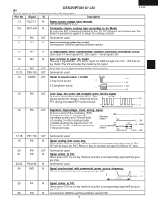
...driving signal To turn on and off shut off the cook relay (RY2). The 16.7 msec. OFF The signals holds "L" level during microwave cooking and "H" level while not cooking. output ON 8 sec. When no key is touched, the signal is detailed in accordance with ...to "H" OFF OFF level and "L" level in operation is touched, a corresponding signal will be input into P41. DESCRIPTION OF LSI LSI The I /O Description R-509FW 1-2 VL2-VL1 IN Power source voltage input terminal. Pin No. B: Completion sound. 0.1 sec. Signal I /O signal of the LSI is held at "H"...
...driving signal To turn on and off shut off the cook relay (RY2). The 16.7 msec. OFF The signals holds "L" level during microwave cooking and "H" level while not cooking. output ON 8 sec. When no key is touched, the signal is detailed in accordance with ...to "H" OFF OFF level and "L" level in operation is touched, a corresponding signal will be input into P41. DESCRIPTION OF LSI LSI The I /O Description R-509FW 1-2 VL2-VL1 IN Power source voltage input terminal. Pin No. B: Completion sound. 0.1 sec. Signal I /O signal of the LSI is held at "H"...

Service Manual
Page 19
... part) Waveguide cover Turntable motor packing Cushion Cushion 1 AB 1 AG 1 AF 1 AD 1 AM 1 AC 1 AC 1 -1 AH 1 AA 1 AB 1 AC 17 R-509FW PARTS LIST Note: The parts marked "∆" may cause undue microwave exposure. PART NO. § DESCRIPTION Q'TY CODE 1- 1 1- 2 1- 3 1- 4 1- 5 1- 6 1- 7 1- 8 1- 9 ∆ 1-10 1-11 1-12 1-13 ELECTRIC PARTS RC-QZB018MRE0 M High voltage capacitor FH...
... part) Waveguide cover Turntable motor packing Cushion Cushion 1 AB 1 AG 1 AF 1 AD 1 AM 1 AC 1 AC 1 -1 AH 1 AA 1 AB 1 AC 17 R-509FW PARTS LIST Note: The parts marked "∆" may cause undue microwave exposure. PART NO. § DESCRIPTION Q'TY CODE 1- 1 1- 2 1- 3 1- 4 1- 5 1- 6 1- 7 1- 8 1- 9 ∆ 1-10 1-11 1-12 1-13 ELECTRIC PARTS RC-QZB018MRE0 M High voltage capacitor FH...


