
Service Manual
Page 1
... SPECIFICATIONS ...4 GENERAL INFORMATION ...4 OPERATION ...6 TEST PROCEDURE ...8 TOUCH CONTROL PANEL ...12 CPU UNIT CIRCUIT ...16 PARTS LIST ...17 PACKING AND ACCESSORIES ...21 This document has been published to those specified should be restored to its original condition and only parts identical to be used in conjunction with the base model service manual for complete operation, service, safety and replacement parts information. R-509FW SUPPLEMENTAL SERVICE MANUAL S22M183R509FE MICROWAVE OVEN MODEL R-509FW R-509FW This is quite similar to change without...
... SPECIFICATIONS ...4 GENERAL INFORMATION ...4 OPERATION ...6 TEST PROCEDURE ...8 TOUCH CONTROL PANEL ...12 CPU UNIT CIRCUIT ...16 PARTS LIST ...17 PACKING AND ACCESSORIES ...21 This document has been published to those specified should be restored to its original condition and only parts identical to be used in conjunction with the base model service manual for complete operation, service, safety and replacement parts information. R-509FW SUPPLEMENTAL SERVICE MANUAL S22M183R509FE MICROWAVE OVEN MODEL R-509FW R-509FW This is quite similar to change without...
Service Manual
Page 2
... unit operates with the door open . (b) Make the following safety checks on all ovens to be serviced before the oven is in this manual before activating the magnetron or other microwave source, and make repairs as per the Microwave Measurement Procedure outlined in excess of the specified limit, contact SHARP ELECTRONICS CORPORATION immediately @1-800-237-4277. The owner of the unit should be instructed...
... unit operates with the door open . (b) Make the following safety checks on all ovens to be serviced before the oven is in this manual before activating the magnetron or other microwave source, and make repairs as per the Microwave Measurement Procedure outlined in excess of the specified limit, contact SHARP ELECTRONICS CORPORATION immediately @1-800-237-4277. The owner of the unit should be instructed...
Service Manual
Page 3
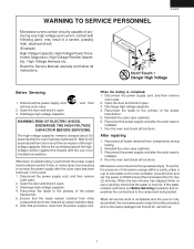
... in a severe, possibly fatal, electrical shock. (Example) High Voltage Capacitor, High Voltage Power Transformer, Magnetron, High Voltage Rectifier Assembly, High Voltage Harness etc.. Disconnect the power supply cord, and then remove outer case. 2. After repairing 1. Reconnect all functions. Microwave ovens should be necessary to the primary of the power transformer. 5. When all service work is completed and the oven is installed. 4. The high-voltage capacitor...
... in a severe, possibly fatal, electrical shock. (Example) High Voltage Capacitor, High Voltage Power Transformer, Magnetron, High Voltage Rectifier Assembly, High Voltage Harness etc.. Disconnect the power supply cord, and then remove outer case. 2. After repairing 1. Reconnect all functions. Microwave ovens should be necessary to the primary of the power transformer. 5. When all service work is completed and the oven is installed. 4. The high-voltage capacitor...
Service Manual
Page 4
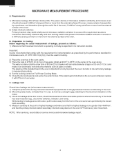
... vents). Requirements: 1) Microwave leakage limit (Power density limit): The power density of microwave radiation emitted by the performance standard for testing: Before beginning the actual measurement of leakage, proceed as follows: 1) Make sure that the primary interlock switch/secondary interlock relay does turn the oven OFF before the survey is measured accurately. 4) Set the cooking control on service invoice and microwave leakage report. 2 B. R-509FW MICROWAVE...
... vents). Requirements: 1) Microwave leakage limit (Power density limit): The power density of microwave radiation emitted by the performance standard for testing: Before beginning the actual measurement of leakage, proceed as follows: 1) Make sure that the primary interlock switch/secondary interlock relay does turn the oven OFF before the survey is measured accurately. 4) Set the cooking control on service invoice and microwave leakage report. 2 B. R-509FW MICROWAVE...
Service Manual
Page 5
... the interlock switches and the door seal carefully. Servicing and repair work must be carried out only by themselves, or when they will be given to voltage above 250V. Removal of electrical shock only during servicing. R-509FW SERVICE MANUAL MICROWAVE OVEN R-509FW FOREWORD This Manual has been prepared to render satisfactory customer service. Service personnel - If provided, Vent Hood, Fan assembly, Cooling Fan Motor. PRODUCT DESCRIPTION GENERAL INFORMATION OPERATION TROUBLESHOOTING GUIDE AND TEST PROCEDURE TOUCH CONTROL PANEL WIRING DIAGRAM PARTS LIST SHARP ELECTRONICS...
... the interlock switches and the door seal carefully. Servicing and repair work must be carried out only by themselves, or when they will be given to voltage above 250V. Removal of electrical shock only during servicing. R-509FW SERVICE MANUAL MICROWAVE OVEN R-509FW FOREWORD This Manual has been prepared to render satisfactory customer service. Service personnel - If provided, Vent Hood, Fan assembly, Cooling Fan Motor. PRODUCT DESCRIPTION GENERAL INFORMATION OPERATION TROUBLESHOOTING GUIDE AND TEST PROCEDURE TOUCH CONTROL PANEL WIRING DIAGRAM PARTS LIST SHARP ELECTRONICS...
Service Manual
Page 6
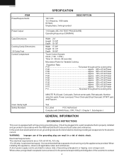
... Full Power P-0 No power throughout the cooking time MINUTE PLUS pad, Cook pads, Defrost center pads, Reheat pads, Number selection pads, Power Level pad, Timer/Clock pad,Stop/Clear pad, START pad, and Popcorn. Oven Cavity Light Safety Standard Yes UL Listed FCC Authorized Complies with the National Electrical Code and local codes and ordinances. fused electrical supply. It must be provided. WARNING: Improper use of electric shock. When installing this appliance be plugged into a wall...
... Full Power P-0 No power throughout the cooking time MINUTE PLUS pad, Cook pads, Defrost center pads, Reheat pads, Number selection pads, Power Level pad, Timer/Clock pad,Stop/Clear pad, START pad, and Popcorn. Oven Cavity Light Safety Standard Yes UL Listed FCC Authorized Complies with the National Electrical Code and local codes and ordinances. fused electrical supply. It must be provided. WARNING: Improper use of electric shock. When installing this appliance be plugged into a wall...
Service Manual
Page 7
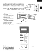
... when the oven is securely closed or the STOP/ CLEAR pad is opened. 6. Push to open button. Removable turntable support. 4. One touch door open door. 2. Oven lamp. or higher rated cord. Grounded Receptacle Box 3-Pronged Plug Grounding Pin 3-Pronged Receptacle OVEN DIAGRAM 1. Oven door with a properly grounded three-pronged wall receptacle or have it can be a 3-wire, 15 amp. Auto-Touch control panel. 9. Time display: Digital display, 99 minutes 99 seconds. 6 2 5 10 4 3 7 9 11 8 1 10. Wave guide cover. 11. Removable turntable. a qualified electrician...
... when the oven is securely closed or the STOP/ CLEAR pad is opened. 6. Push to open button. Removable turntable support. 4. One touch door open door. 2. Oven lamp. or higher rated cord. Grounded Receptacle Box 3-Pronged Plug Grounding Pin 3-Pronged Receptacle OVEN DIAGRAM 1. Oven door with a properly grounded three-pronged wall receptacle or have it can be a 3-wire, 15 amp. Auto-Touch control panel. 9. Time display: Digital display, 99 minutes 99 seconds. 6 2 5 10 4 3 7 9 11 8 1 10. Wave guide cover. 11. Removable turntable. a qualified electrician...
Service Manual
Page 8
...-out displays the time still remaining in the cook cycle when the door was opened during oven operation. To set any program or set the clock, you must first touch the STOP/CLEAR pad. The contacts of the primary interlock switch and secondary interlock relay VARI-MODE Power 10(P-HI) (100% power) Power 9(P-90) (approx. 90% power) Power 8(P-80) (approx. 80% power) Power 7(P-70) (approx. 70% power) Power 6(P-60) (approx. 60% power) Power 5(P-50) (approx. 50% power) Power...
...-out displays the time still remaining in the cook cycle when the door was opened during oven operation. To set any program or set the clock, you must first touch the STOP/CLEAR pad. The contacts of the primary interlock switch and secondary interlock relay VARI-MODE Power 10(P-HI) (100% power) Power 9(P-90) (approx. 90% power) Power 8(P-80) (approx. 80% power) Power 7(P-70) (approx. 70% power) Power 6(P-60) (approx. 60% power) Power 5(P-50) (approx. 50% power) Power...
Service Manual
Page 9
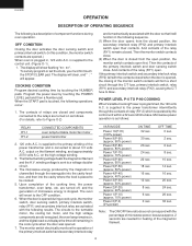
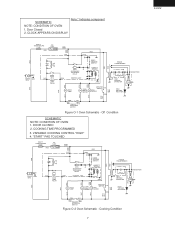
... WHT INTERLOCK SWITCH Figure O-1 Oven Schematic - DOOR CLOSED 2. "START" PAD TOUCHED WHT CAVITY TEMPERATURE FUSE RED C/T FUSE RED GRN 120VAC GND 60Hz N.O. (RY1) OVEN LAMP RELAY GRY ORG ORG N.O. RED COM. B2 DOOR SENSING SWITCH COM. (RY2) SECONDARY INTERLOCK RELAY CONTROL UNIT B1 HUMIDITY SENSOR F3 F2 F1 ORG ORG BRN ORG OL OVEN LAMP TTM TURN TABLE FM MOTOR MONITOR SWITCH N.C. FAN MOTOR COM. SCHEMATIC NOTE: CONDITION OF OVEN 1. Door Closed 2. N.O. CLOCK APPEARS ON DISPLAY Note...
... WHT INTERLOCK SWITCH Figure O-1 Oven Schematic - DOOR CLOSED 2. "START" PAD TOUCHED WHT CAVITY TEMPERATURE FUSE RED C/T FUSE RED GRN 120VAC GND 60Hz N.O. (RY1) OVEN LAMP RELAY GRY ORG ORG N.O. RED COM. B2 DOOR SENSING SWITCH COM. (RY2) SECONDARY INTERLOCK RELAY CONTROL UNIT B1 HUMIDITY SENSOR F3 F2 F1 ORG ORG BRN ORG OL OVEN LAMP TTM TURN TABLE FM MOTOR MONITOR SWITCH N.C. FAN MOTOR COM. SCHEMATIC NOTE: CONDITION OF OVEN 1. Door Closed 2. N.O. CLOCK APPEARS ON DISPLAY Note...
Service Manual
Page 10
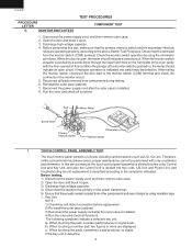
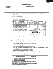
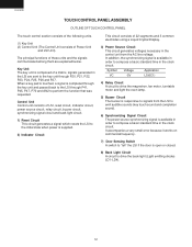
... PROCEDURES COMPONENT TEST 1. Reinstall the outer case (cabinet). 7. Reconnect the power supply cord after the outer case is open circuit. Red White/ White Screw Driver Primary Interlock Switch Ohmmeter Monitor Switch I TOUCH CONTROL PANEL ASSEMBLY TEST The touch control panel consists of the power transformer. 5) Ensure that the primary interlock switch and the secondary interlock relay are displayed. When the door is installed. 4) Run the oven and check all functions. Run the...
... PROCEDURES COMPONENT TEST 1. Reinstall the outer case (cabinet). 7. Reconnect the power supply cord after the outer case is open circuit. Red White/ White Screw Driver Primary Interlock Switch Ohmmeter Monitor Switch I TOUCH CONTROL PANEL ASSEMBLY TEST The touch control panel consists of the power transformer. 5) Ensure that the primary interlock switch and the secondary interlock relay are displayed. When the door is installed. 4) Run the oven and check all functions. Run the...
Service Manual
Page 11
..., 1) Disconnect the power supply cord, and then remove outer case. 2) Open the door and block it open. 3. a) Buzzer does not sound or continues to determine if the control unit or key pad is installed. 7) Run the oven and check all functions.. J KEY UNIT TEST 1. Discharge high voltage capacitor. 4. Use the Key unit matrix indicated on the control panel schematic and place a jumper wire between the...
..., 1) Disconnect the power supply cord, and then remove outer case. 2) Open the door and block it open. 3. a) Buzzer does not sound or continues to determine if the control unit or key pad is installed. 7) Run the oven and check all functions.. J KEY UNIT TEST 1. Discharge high voltage capacitor. 4. Use the Key unit matrix indicated on the control panel schematic and place a jumper wire between the...
Service Manual
Page 12
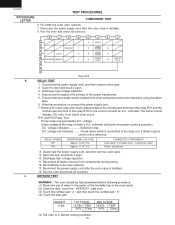
... functions. 8 7 6 5 4 3 2 1 DEFROST 1 COOK 4 POPCORN REHEAT 7 2 START 5 TIMER CLOCK 9 8 STOP CLEAR 3 0 POWER LEVEL 6 MINUTE PLUS 14 13 12 11 10 9 Key Unit K RELAY TEST 1. Re-install the outer case (cabinet). 13. R-509FW TEST PROCEDURES PROCEDURE LETTER COMPONENT TEST 6. Open the door and block it open terminal of the turntable tray in Defrost cooking condition. 10 Ensure that procedure, re-connect the power supply cord. 7. voltmeter.The meter should be fully assembled before following...
... functions. 8 7 6 5 4 3 2 1 DEFROST 1 COOK 4 POPCORN REHEAT 7 2 START 5 TIMER CLOCK 9 8 STOP CLEAR 3 0 POWER LEVEL 6 MINUTE PLUS 14 13 12 11 10 9 Key Unit K RELAY TEST 1. Re-install the outer case (cabinet). 13. R-509FW TEST PROCEDURES PROCEDURE LETTER COMPONENT TEST 6. Open the door and block it open terminal of the turntable tray in Defrost cooking condition. 10 Ensure that procedure, re-connect the power supply cord. 7. voltmeter.The meter should be fully assembled before following...
Service Manual
Page 13
... resistance which is installed. 9) Run the oven and check all leads removed from other components and oven chassis by using insulation tape. 6) After that procedure, re-connect the power supply cord. 7) Follow the troubleshooting guide given below , if indicator does not light up after above check and repairs are broken. Low voltage transformer or secondary circuit defective. Follow the troubleshooting guide given below for...
... resistance which is installed. 9) Run the oven and check all leads removed from other components and oven chassis by using insulation tape. 6) After that procedure, re-connect the power supply cord. 7) Follow the troubleshooting guide given below , if indicator does not light up after above check and repairs are broken. Low voltage transformer or secondary circuit defective. Follow the troubleshooting guide given below for...
Service Manual
Page 14
... magnetron, fan motor, turntable motor and light the oven lamp. 5) Buzzer Circuit The buzzer is responsive to signals from the AC line voltage. It accompanies a very small error because it works on commercial frequency. 7) Door Sensing Switch A switch to "tell" the LSI if the door is available in order to compose a basic standard time in the control unit from the LSI to emit audible sounds (key touch sound and completion sound...
... magnetron, fan motor, turntable motor and light the oven lamp. 5) Buzzer Circuit The buzzer is responsive to signals from the AC line voltage. It accompanies a very small error because it works on commercial frequency. 7) Door Sensing Switch A switch to "tell" the LSI if the door is available in order to compose a basic standard time in the control unit from the LSI to emit audible sounds (key touch sound and completion sound...
Service Manual
Page 15
... power source frequency. Signal I /O signal of signals P20 - By using the A/D converter contained in the LSI, DC voltage in the following table. Door close information to the Model. G8 lines on and off relay (RY1). B Oven lamp, fan motor and turntable motor driving signal To turn on key matrix.The LSI will be input into P47. OFF The signals holds "L" level during microwave cooking and "H" level...
... power source frequency. Signal I /O signal of signals P20 - By using the A/D converter contained in the LSI, DC voltage in the following table. Door close information to the Model. G8 lines on and off relay (RY1). B Oven lamp, fan motor and turntable motor driving signal To turn on key matrix.The LSI will be input into P47. OFF The signals holds "L" level during microwave cooking and "H" level...
Service Manual
Page 16
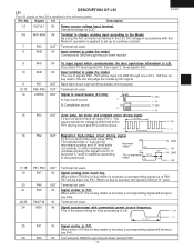
... R-509FW Pin No. Power source voltage: -5.0V. A pulse signal is input to P41, P45, P47 and P70 terminal while one of G7 line keys on key matrix is touched. A pulse signal is reset. Temporarily set at this time the LSI is input to control oscillation input of power source circuit input. Internal clock oscillation frequency input setting. The internal clock frequency is touched...
... R-509FW Pin No. Power source voltage: -5.0V. A pulse signal is input to P41, P45, P47 and P70 terminal while one of G7 line keys on key matrix is touched. A pulse signal is reset. Temporarily set at this time the LSI is input to control oscillation input of power source circuit input. Internal clock oscillation frequency input setting. The internal clock frequency is touched...
Service Manual
Page 18
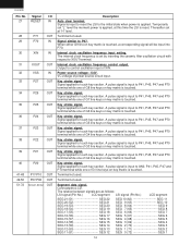
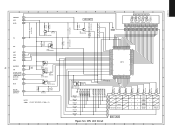
...2SA1037AK C10 0.1µ/50v INT 44 AN7 46 AN6 47 AN5 48 AN4 49 BUZZER 50 VR 43 OVEN LAMP FAN MOTOR TURNTABLE 51 MOTOR MICRO 52 D20 53 DOOR SENSING 54 SWITCH R30 3.3k R40 4.7k C40 0.01µ /25v Q10 DTA143EKA Q30 DTA143EKA C20 Q20 0.1µ...LIQUID CRYSTAL DISPLAY COOK DEFROST SENSOR NO. CPU Unit Circuit C65 330p/50v C64 330p/50v C63 330p/50v C62 330p/50v C61 330p/50v C60 330p/50v 14 13 12 11 10 9 R67 15k R66 15k R65 15k R64 15k 8 7 6 5 DEFROST 1 COOK 4 POPCORN REHEAT 7 4 3 2 1 2 START 5 TIMER CLOCK 9 8 STOP CLEAR 3 0 POWER LEVEL 6 ...
...2SA1037AK C10 0.1µ/50v INT 44 AN7 46 AN6 47 AN5 48 AN4 49 BUZZER 50 VR 43 OVEN LAMP FAN MOTOR TURNTABLE 51 MOTOR MICRO 52 D20 53 DOOR SENSING 54 SWITCH R30 3.3k R40 4.7k C40 0.01µ /25v Q10 DTA143EKA Q30 DTA143EKA C20 Q20 0.1µ...LIQUID CRYSTAL DISPLAY COOK DEFROST SENSOR NO. CPU Unit Circuit C65 330p/50v C64 330p/50v C63 330p/50v C62 330p/50v C61 330p/50v C60 330p/50v 14 13 12 11 10 9 R67 15k R66 15k R65 15k R64 15k 8 7 6 5 DEFROST 1 COOK 4 POPCORN REHEAT 7 4 3 2 1 2 START 5 TIMER CLOCK 9 8 STOP CLEAR 3 0 POWER LEVEL 6 ...

Service Manual
Page 19
... Chassis support Latch hook Switch lever Magnetron duct Fan blade Fan duct Oven cavity (Not a replaceable part) Waveguide cover Turntable motor packing Cushion Cushion 1 AB 1 AG 1 AF 1 AD 1 AM 1 AC 1 AC 1 -1 AH 1 AA 1 AB 1 AC 17 PART NO. § DESCRIPTION Q'TY CODE 1- 1 1- 2 1- 3 1- 4 1- 5 1- 6 1- 7 1- 8 1- 9 ∆ 1-10 1-11 1-12 1-13 ELECTRIC PARTS RC-QZB018MRE0 M High voltage capacitor FH-DZB013MRY0 M High voltage rectifier assembly QSOCLB006MRE0 M Oven lamp socket RLMPTA068WRE0 M Oven lamp RMOTEA346WRE0 M Fan motor FFS-BA019/KIT M Monitor switch (V-16G-2C25), C/T fuse (20A...
... Chassis support Latch hook Switch lever Magnetron duct Fan blade Fan duct Oven cavity (Not a replaceable part) Waveguide cover Turntable motor packing Cushion Cushion 1 AB 1 AG 1 AF 1 AD 1 AM 1 AC 1 AC 1 -1 AH 1 AA 1 AB 1 AC 17 PART NO. § DESCRIPTION Q'TY CODE 1- 1 1- 2 1- 3 1- 4 1- 5 1- 6 1- 7 1- 8 1- 9 ∆ 1-10 1-11 1-12 1-13 ELECTRIC PARTS RC-QZB018MRE0 M High voltage capacitor FH-DZB013MRY0 M High voltage rectifier assembly QSOCLB006MRE0 M Oven lamp socket RLMPTA068WRE0 M Oven lamp RMOTEA346WRE0 M Fan motor FFS-BA019/KIT M Monitor switch (V-16G-2C25), C/T fuse (20A...
Service Manual
Page 20
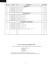
... 5- 6 5- 7 DOOR PARTS FCOV-B205MRK0 M Door frame assembly LSTPPB021MRF0 M Latch head MSPRTA046WRE0 M Latch spring FDORFB049MRT0 M Door panel PSHEPB016MRE0 M Sealer film HPNL-B090MRE0 M Door screen GCOVHB039MRF0 M Choke cover 6- 1 6- 2 6- 3 6- 4 6- 5 6- 6 6- 7 6- 8 6- 9 MISCELLANEOUS FW-VZB125MRE0 M Stop switch harness FW-VZB192MRE0 M Main wire harnes TLABBB007MRE0 M Cavity hole cover FROLPB025MRK0 M Turntable support NTNT-A099WRE0 M Turntable tray TCAUAB045MRR0 M Monitor caution label TCAUAB038MRR0 M DHHS/Screw caution label TINSEB306MRK0 M Operation manual QW-QZB016MRE0 M High voltage wire...
... 5- 6 5- 7 DOOR PARTS FCOV-B205MRK0 M Door frame assembly LSTPPB021MRF0 M Latch head MSPRTA046WRE0 M Latch spring FDORFB049MRT0 M Door panel PSHEPB016MRE0 M Sealer film HPNL-B090MRE0 M Door screen GCOVHB039MRF0 M Choke cover 6- 1 6- 2 6- 3 6- 4 6- 5 6- 6 6- 7 6- 8 6- 9 MISCELLANEOUS FW-VZB125MRE0 M Stop switch harness FW-VZB192MRE0 M Main wire harnes TLABBB007MRE0 M Cavity hole cover FROLPB025MRK0 M Turntable support NTNT-A099WRE0 M Turntable tray TCAUAB045MRR0 M Monitor caution label TCAUAB038MRR0 M DHHS/Screw caution label TINSEB306MRK0 M Operation manual QW-QZB016MRE0 M High voltage wire...
Service Manual
Page 23
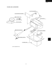
PACKING AND ACCESSORIES DOOR PROTECTION SHEET 6-5 TURNTABLE TRAY ON TOP OF THE OVEN TRAY HOLDER R-509FW TOP PAD ASSEMBLY PLASTIC BAG 6-8 OPERATION MANUAL INTO THE OVEN CAVITY BOTTOM PAD ASSEMBLY 6-4 TURNTABLE SUPPORT PACKING CASE Non-replaceable items 21
PACKING AND ACCESSORIES DOOR PROTECTION SHEET 6-5 TURNTABLE TRAY ON TOP OF THE OVEN TRAY HOLDER R-509FW TOP PAD ASSEMBLY PLASTIC BAG 6-8 OPERATION MANUAL INTO THE OVEN CAVITY BOTTOM PAD ASSEMBLY 6-4 TURNTABLE SUPPORT PACKING CASE Non-replaceable items 21

